V-series M4A3000E ASUS PC (Desktop Barebone) User’s Manual R
E5233 First Edition V1 December 2009 Copyright © 2009 ASUSTeK Computer Inc. All Rights Reserved. No part of this manual, including the products and software described in it, may be reproduced, transmitted, transcribed, stored in a retrieval system, or translated into any language in any form or by any means, except documentation kept by the purchaser for backup purposes, without the express written permission of ASUSTeK Computer Inc. (“ASUS”).
Table of contents Notices.......................................................................................................... vi Safety information...................................................................................... vii About this guide........................................................................................ viii System package contents............................................................................ x Chapter 1: 1.1 1.2 1.3 1.4 1.5 Welcome!............
Table of contents Chapter 4: 4.1 Managing and updating your BIOS............................................. 4-2 4.1.1 ASUS Update utility......................................................... 4-2 4.1.3 ASUS CrashFree BIOS 3 utility....................................... 4-6 4.1.2 4.2 4.2.1 BIOS menu screen........................................................... 4-8 4.2.3 Navigation keys................................................................ 4-8 4.2.4 4.2.5 4.2.6 4.2.7 4.2.8 4.2.
Table of contents 4.6 Boot menu................................................................................... 4-24 4.6.1 Boot Device Priority....................................................... 4-24 4.6.3 Security.......................................................................... 4-26 4.6.2 4.7 Tools menu.................................................................................. 4-28 4.7.1 ASUS EZ Flash 2........................................................... 4-28 4.7.
Notices Federal Communications Commission Statement This device complies with Part 15 of the FCC Rules. Operation is subject to the following two conditions: • • This device may not cause harmful interference, and This device must accept any interference received including interference that may cause undesired operation. This equipment has been tested and found to comply with the limits for a Class B digital device, pursuant to Part 15 of the FCC Rules.
Safety information Electrical safety • • • To prevent electrical shock hazard, disconnect the power cable from the electrical outlet before relocating the system. When adding or removing devices to or from the system, ensure that the power cables for the devices are unplugged before the signal cables are connected. If the power supply is broken, do not try to fix it by yourself. Contact a qualified service technician or your retailer.
DO NOT throw the Barebone system’s components in municipal waste. This product has been designed to enable proper reuse of parts and recycling. This symbol of the crossed out wheeled bin indicates that the product (electrical and electronic equipment) should not be placed in municipal waste. Check local regulations for disposal of electronic products. DO NOT throw the mercury-containing button cell battery in municipal waste.
Conventions used in this guide WARNING: Information to prevent injury to yourself when trying to complete a task. CAUTION: Information to prevent damage to the components when trying to complete a task. IMPORTANT: Instructions that you MUST follow to complete a task. NOTE: Tips and additional information to aid in completing a task. Where to find more information Refer to the following sources for additional information and for product and software updates. 1. 2.
System package contents Check your V-series M4A3000E system package for the following items. If any of the items is damaged or missing, contact your retailer immediately. Item description 1. ASUS V-series M4A3000E barebone system with • ASUS motherboatd • Power supply unit • ASUS chassis 2. Cable 3. Support DVD • AC power cable 4. Quick Installation Guide 5.
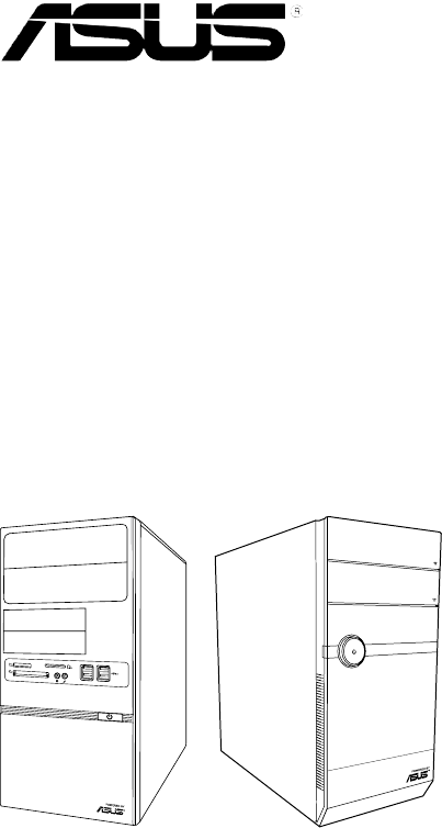
This chapter gives a general description of the ASUS V-series M4A3000E. The chapter lists the system features including introduction on the front and rear panel, and internal components.
1.1 Welcome! Thank you for choosing the ASUS V-series M4A3000E! The ASUS V-series M4A3000E is an all-in-one barebone system with a versatile home entertainment feature. The system comes in a stylish casing and powered by the ASUS motherboard that supports the AMD® AM3 socket for AMD® Phenom™ II / Athlon™ II / Sempron™ 100 series processors. The system supports up to 8 GB of system memory using DDR3-1800(O.C.)/ 1600(O.C.)/1333/1066MHz DIMMs.
1. 2. 3. 4. 5. 6. 7. 8. 9. Two empty 5.25-inch drive bays. These bays are for 5.25-inch IDE/SATA optical drives. Two empty 3.5-inch drive bays. These bays are for 3.5-inch hard disk drives. MemoryStick® / Memory Stick Pro™ card slot Secure Digital™/ Multimedia Card slot CompactFlash® / Microdrive™ card slot USB 2.0 ports. These Universal Serial Bus 2.0 (USB 2.0) ports are available for connecting USB 2.0 devices such as a mouse, printer, scanner, camera, PDA, and others. Microphone port.
1. 2. 3. 4. 5. 6. Optical disk drive bay (empty). You may install an additional optical disk drive in this bay. Optical disk drive eject button. Press this button to eject the optical disk drive tray. Optical disk drive bay (empty). You may install an additional optical disk drive in this bay. Front I/O ports cover. Power button. Press this button to turn the system on. MemoryStick® / Memory Stick Pro™ card slot, Secure Digital™/ Multimedia Card slot, CompactFlash® / Microdrive™ card slot, USB 2.
1.3 Rear panel The system rear panel includes the power connector and several I/O ports that allow convenient connection of devices. 3 1 4 2 6 5 7 DVI 8 9 10 11 14 12 13 15 Do NOT cover the rear vent , and the ambient temperature is limited up to 35oC to prevent the system from overheating. 1. 2. 3. Voltage selector. This switch allows you to adjust the system input voltage according to the voltage supply in your area.
4. 5. 6. 7. 8. 9. Power Switch. This switch is for switching on/off the power supply unit. Chassis fan vent. This vent is for the fan that provides ventilation inside the system chassis. PS/2 mouse port. This green 6-pin connector is for a PS/2 mouse. PS/2 keyboard port. This purple 6-pin connector is for a PS/2 keyboard. DVI-D Out port. This port is for any DVI-D compatible device and is HDCP compliant allowing playback of HD DVD, Blu-Ray and other protected content. Video Graphics Adapter (VGA) port.
Refer to the audio configuration table below for the function of the audio ports in 2, 4, or 6-channel configuration. Audio 2, 4, or 6-channel configuration Port Light Blue Lime Pink Headset 2-channel Line In Line Out Mic In 4-channel Rear Speaker Out Front Speaker Out Mic In 6-channel Rear Speaker Out Front Speaker Out Bass/Center 15. Expansion slot covers. Remove these covers when installing expansion cards.
1.4 Internal components The illustration below is the internal view of the system when you remove the side cover and the power supply unit. The installed components are labeled for your reference. 5 2 6 3 7 4 8 9 1 10 M4A78LT-M LE 12 1. 2. 3. 4. 5. 6. 11 Front panel cover 5.25-inch optical drive bays 3.5-inch drive bay Hard disk drive bay Power supply unit CPU socket 7. 8. 9. 10. 11. 12.
1.5 Qualified Vendors Lists (QVL) DDR3-1066MHz capability DIMM socket support (Optional) Vendor Part No. Size SS/ DS Chip Brand Chip NO. Timing Voltage A* B* Crucial CT25664BA1067.16FF 2048MB DS Micron 9HF22D9KPT 7 - • • Crucial CT25672BA1067.18FF 2048MB DS Micron 9GF22D9KPT(ECC) 7 - • • Elpida EBJ51UD8BAFA-AE-E 512MB SS Elpida J5308BASE-AC-E - - • • Kingston KVR1066D3N7/1G 1024MB SS Kingston D1288JEKAPGA7U 7 1.
1-10 Chapter 1: System introduction
Chapter 2 R Starting up This chapter helps you power up the system and install drivers and utilities from the support DVD.
2.1 Installing an operating system The barebone system supports Windows® XP/Vista/7 operating systems (OS). Always install the latest OS version and corresponding updates so you can maximize the features of your hardware. Motherboard settings and hardware options vary. Use the setup procedures presented in this chapter for general reference only. Refer to your OS documentation for more information. 2.
2.3.1 Running the support DVD To begin using the support DVD, place the DVD in your optical drive. The DVD automatically displays the Drivers menu if Autorun is enabled in your computer. Click an icon to display support DVD/motherboard information Click an item to install If Autorun is NOT enabled in your computer, browse the contents of the support DVD to locate the file ASSETUP.EXE from the BIN folder. Double-click the ASSETUP.EXE to run the DVD. AMD Chipset Driver Installs the AMD® chipset driver.
2.3.2 Utilities menu The Utilities menu shows the applications and other software that the motherboard supports. ASUS Cool ‘n’ Quiet Utility Installs ASUS Cool ‘n’ Quiet utility. ASUS Update Allows you to download the latest version of the BIOS from the ASUS website. Before using the ASUS Update, make sure that you have an Internet connection so you can connect to the ASUS website. ASUS AI Manager Installs the ASUS AI Manager. Atheros Ethernet Utility Installs the Atheros® Ethernet Utility.
ASUS Turbo Key Installs ASUS Turbo Key. ASUS Express Gate Installer Installs the ASUS Express Gate application. Microsoft DirectX 9.0c Installs the Microsoft® DirectX 9.0c driver. The Microsoft DirectX® 9.0c is a multimedia technology that enhances computer graphics and sound. DirectX® improves the multimedia features of you computer so you can enjoy watching TV and movies, capturing videos, or playing games in your computer. Visit the Microsoft website (www.microsoft.com) for updates. 2.3.
2.3.4 Manual menu The Manual menu contains a list of supplementary user manuals. Click an item to open the folder of the user manual. Most user manual files are in Portable Document Format (PDF). Install the Adobe® Reader from the Utilities menu before opening a user manual file. ASUS Motherboard Installation Guide Allows you to open the ASUS Motherboard Installation Guide. ASUS Motherboard Utility Guide Allows you to open the ASUS Motherboard Utility Guide.
2.3.5 ASUS Contact information Click the Contact tab to display the ASUS contact information. You can also find this information on the inside front cover of this user guide.
2.3.6 Other information The icons on the top right corner of the screen give additional information on the motherboard and the contents of the support DVD. Click an icon to display the specified information. Motherboard Info Displays the general specifications of the motherboard. ASUSTeK Computer INC. M4A78LT-M-LE Rev X.0x American Megatrends Inc. 0201 11/16/2009 1024 KBytes Browse this DVD Displays the support DVD contents in graphical format.
Filelist Displays the contents of the support DVD and a brief description of each in text format.
2.4 Software information Most of the applications in the support DVD have wizards that will conveniently guide you through the installation. View the online help or readme file that came with the software for more information. 2.4.1 ASUS AI Manager ASUS AI Manager is a utility which gives you quick and easy access to frequentlyused applications. Installing AI Manager To install AI Manager on your computer: 1. Place the support CD in the optical drive.
AI Manager quick bar The AI Manager quick bar saves the desktop space and allows you to launch the ASUS utilities or display system information easily. Click any of the Main, My Favorites, Support or Information tab to display the menu’s contents. Close button Maximize / restore button Minimize button Main My Favorites Support Information Click the Maximize/restore button to switch between full window and quick bar. Click the Minimize button to keep the AI Manager on the taskbar.
AI Security AI Security enables you to set a password to secure your devices, such as USB flash disks and CD/DVD disks, from unauthorized access. To lock a device: 1. 2. 3. 4. 5. 6. When using AI Security for the first time, you are asked to set a password. Enter a password with at most 20 alphanumeric characters. Confirm the password. Key in the password hint (recommended). When done, click Ok. Select the device you want to lock, then click Apply.
AI Booting AI Booting allows you to specify the boot device priority sequence. To specify the boot sequence: 1. 2. Select a device, then click on the left/right button to specify the boot sequence. When done, press Apply. AI Probe AI Probe automatically detects and displays the motherboard and CPU temperatures, CPU fan speed, and the voltage output. You can adjust the values as you need.
My Favorites My Favorites allows you to add applications that you frequently use, saving you from searching for the applications throughout your computer. To add an application: 1. 2. Click Add, then locate the application you want to add to My Favorites. Click Open on the file location window. The application is added to My Favorites list. Right click on the application icon to launch, delete, or rename the selected application. You can also double click to launch the selected application.
Support Click any links on the Support window to go to the ASUS website, technical support website, download support website, or contact information. Information Click the tab on the Information window to see the detailed information about your system, motherboard, CPU, BIOS, installed device(s), and memory.
2.4.2 ASUS Express Gate ASUS Express Gate is an instant-on environment that gives you quick access to the Internet. Eight seconds after powering on your computer, you can instantly surf the Internet, use Skype or other Express Gate applications without entering the Windows® OS. • The actual boot time depends on the system configuration. • Download the latest Express Gate version from the ASUS website at www. asus.com.
5. 6. Select the target drive where you want to install Express Gate. If you have multiple partitions installed on your computer, it is recommended to install Express Gate in Drive C. Click Next to continue. Follow the onscreen instructions to complete the installation. The Splash Screen The Express Gate’s splash screen appears eight seconds after you power on your computer. The actual boot time depends on the system configuration.
Express Gate Environment hot-keys: Key Function + Switch between softwares + + Bring up Power-Off dialog box + + Save screen snapshot as picture to file When you are using ASUS Express Gate for the first time, launch an application from the splash screen, a first-time wizard will appear and guide you through basic Express Gate configurations including language, date, and time.
The smaller icons on the right side of the LaunchBar are: Displays your Express Gate version. Launches the help file. Launches the Configuration Panel which allows you to specify network settings and other settings. Configures the network. Adjusts the volume. This icon appears only when a removable storage device / USB drive is connected. Left-click this icon to launch the File Manager window. Rightclick it to eject the removable storage device / USB drive.
• LAN settings If you connect your computer to a home router that is connected to your DSL/ cable modem, enable all the LAN ports. Express Gate automatically uses the connected port. If you plug the network cable into a different port while Express Gate is running (e.g. move the cable from LAN1 to LAN2, restart Express Gate to activate the new setting. If your computer does not automatically get network settings from a DHCP server, click Setup to configure the static IP settings manually.
Using the Online Games Express Gate introduces a Splashtop Gaming portal site which provides interesting games in different categories. Enable the Internet connection to use the Online Games feature. Using the Photo Manager Photo Manager allows you to view pictures saved on your hard drive or external storage devices. You can view pictures in thumbnail view, in an enlarged view individually, in a filename/data list view, or play them in a slideshow. JPEG, GIF, BMP, and PNG formats are supported.
Configuring Express Gate in BIOS Setup To enter the motherboard BIOS Setup program, click Exit on the splash screen and then hold down during POST. Go to the Tools menu to configure Express Gate. Refer to 4.7.2 Express Gate for details. Main Advanced Power BIOS SETUP UTILITY Boot Tools Exit ASUS EZ Flash 2 Express Gate Enter OS Timer Reset User Data [Auto] [10 Seconds] [No] Press ENTER to run the utility to select and update BIOS. This utility supports 1.FAT 12/16/32 (r/w) 2.NTFS (read only) 3.
This chapter gives information about he motherboard that comes with the system. This chapter includes the motherboard layout, jumper settings, and connector locations.
3.1 Introduction The Vintage V-series M4A3000E barebone system comes with an ASUS motherboard. This chapter provides technical information about the motherboard for future upgrades or system reconfiguration. 3.2 Motherboard layout 20.8cm(8.2in) KBPWR KBMS LAN1_USB12 AUDIO ICS 9LPRS485 SPDIF_OUT CHA_FAN COM1 PCIEX1_1 CLRTC 24.4cm(9.
3.3 1. Jumpers Clear RTC RAM (3-pin CLRTC) This jumper allows you to clear the Real Time Clock (RTC) RAM in CMOS. You can clear the CMOS memory of date, time, and system setup parameters by erasing the CMOS RTC RAM data. The onboard button cell battery powers the RAM data in CMOS, which include system setup information such as system passwords. To erase the RTC RAM: 1. Turn OFF the computer and unplug the power cord. 2. Move the jumper cap from pins 1-2 (default) to pins 2-3.
2. USB device wake-up (3-pin USBPW1-4, USBPW5-10) Set these jumpers to +5V to wake up the computer from S1 sleep mode (CPU stopped, DRAM refreshed, system running in low power mode) using the connected USB devices. Set these jumpers to +5VSB to wake up the compurer from S3 and S4 sleep modes (no power to CPU, DRAM in slow refresh, power supply in reduced power mode). 1 2 2 3 USBPW1-4 +5VSB (Default) +5V USBPW5-10 1 2 3 2 M4A78LT-M LE +5VSB +5V (Default) M4A78LT-M LE USB device wake-up 3.
3.4 1. Connectors Serial port connectors (10-1 pin COM1) The connector is for a serial (COM) port. Connect the serial port module cable to the connector, then install the module to a slot opening at the back of the system chassis. The serial port bracket (COM1) is purchased separately. COM1 PIN 1 M4A78LT-M LE M4A78LT-M LE Serial port (COM1) connector Serial ATA connectors (7-pin SATA1~6) These connectors are for the Serial ATA signal cables for Serial ATA hard disk drives.
3. IDE connector (40-1 pin PRI_IDE) The onboard IDE connector is for the Ultra DMA 133/100 signal cable. There are three connectors on each Ultra DMA 133/100 signal cable: blue, black, and gray. Connect the blue connector to the motherboard’s IDE connector, then select one of the following modes to configure your device.
USB connectors (10-1 pin USB56, USB78, USB910) These connectors are for USB 2.0 ports. Connect the USB module cable to any of these connectors, then install the module to a slot opening at the back of the system chassis. These USB connectors comply with USB 2.0 specification that supports up to 480 Mbps connection speed.
6. CPU, chassis and power fan connectors . (4-pin CPU_FAN, 3-pin CHA_FAN) Connect the fan cables to the fan connectors on the motherboard, ensuring that the black wire of each cable matches the ground pin of the connector. DO NOT forget to connect the fan cables to the fan connectors. Insufficient air flow inside the system may damage the motherboard components.
Front panel audio connector (10-1 pin AAFP) NC AGND NC NC SENSE2_RETUR This connector is for a chassis-mounted front panel audio I/O module that supports either HD Audio or legacy AC’97 audio standard. GND PRESENCE# SENSE1_RETUR 8. AAFP M4A78LT-M LE HD-audio-compliant pin definition PIN 1 MIC2 MICPWR Line out_R NC Line out_L PORT1 L PORT1 R PORT2 R SENSE_SEND PORT2 L PIN 1 Legacy AC’97 compliant definition M4A78LT-M LE Front panel audio connector 9.
10. ATX power connectors (24-pin EATXPWR, 4-pin ATX12V) These connectors are for ATX power supply plugs. The power supply plugs are designed to fit these connectors in only one orientation. Find the proper orientation and push down firmly until the connectors completely fit.
11. System panel connector (10-1 pin F_PANEL) This connector supports several chassis-mounted functions. PWRBTN PLED+ PLEDPWR GND PLED M4A78LT-M LE PIN 1 HD_LED+ HD_LEDGround Reset F_PANEL +HDLED RESET M4A78LT-M LE System panel connector • System power LED (2-pin PLED) • Hard disk drive activity LED (2-pin +HDLED) • ATX power button/soft-off button (2-pin PWRBTN) • Reset button (2-pin RESET) This 2-pin connector is for the system power LED.
3-12 Chapter 3: Motherboard info
Chapter 4 R BIOS setup This chapter tells how to change system settings through the BIOS Setup menus and describes the BIOS parameters.
4.1 Managing and updating your BIOS The following utilities allow you to manage and update the motherboard Basic Input/Output System (BIOS) setup. ASUS Update: Updates the BIOS in Windows® environment. 1. ASUS EZ Flash 2: Updates the BIOS using a USB flash disk. 2. ASUS CrashFree BIOS 3: Updates the BIOS using a bootable USB flash disk or the motherboard support DVD when the BIOS file fails or gets corrupted. 3. Refer to the corresponding sections for details on these utilities.
Updating the BIOS through the Internet To update the BIOS through the Internet: 1. Launch the ASUS Update utility from the Windows® desktop by clicking Start > Programs > ASUS > ASUSUpdate > ASUSUpdate. The ASUS Update main window appears. 2. Select Update BIOS from the Internet option from the drop‑down menu, then click Next. ASUS V-series M4A3000E 3. Select the ASUS FTP site nearest you to avoid network traffic, or click Auto Select. Click Next.
4. 5. From the FTP site, select the BIOS version that you wish to download. Click Next. Follow the screen instructions to complete the update process. The ASUS Update utility is capable of updating itself through the Internet. Always update the utility to avail all its features. Updating the BIOS through a BIOS file To update the BIOS through a BIOS file: 1. 2. 3. 4. Launch the ASUS Update utility from the Windows® desktop by clicking Start > Programs > ASUS > ASUSUpdate > ASUSUpdate.
4.1.2 ASUS EZ Flash 2 utility The ASUS EZ Flash 2 feature allows you to update the BIOS without having to go through the long process of booting from a floppy disk and using a DOS‑based utility. The EZ Flash 2 utility is built-in the BIOS chip so it is accessible by pressing + during the Power-On Self Tests (POST). To update the BIOS using EZ Flash 2: 1. 2. 3. Visit the ASUS website (www.asus.com) to download the latest BIOS file for the motherboard.
4.1.3 ASUS CrashFree BIOS 3 utility The ASUS CrashFree BIOS 3 is an auto recovery tool that allows you to restore the BIOS file when it fails or gets corrupted during the updating process. You can update a corrupted BIOS file using the motherboard support DVD or a removable device that contains the updated BIOS file. • Before using this utility, rename the BIOS file in the removable device into MA78TMLE.ROM. • The BIOS file in the support DVD may not be the latest version.
4.2 BIOS setup program This motherboard supports a programmable Serial Peripheral Interface (SPI) chip that you can update using the provided utility described in section “4.1 Managing and updating your BIOS”. Use the BIOS Setup program when you are installing a motherboard, reconfiguring your system, or prompted to “Run Setup”. This section explains how to configure your system using this utility.
4.2.1 BIOS menu screen Menu items Main Menu bar Advanced Power Configuration fields BIOS SETUP UTILITY Boot Tools System Time System Date [12:56:38] [Tue 11/24/2009 Primary IDE Master Primary IDE Slave SATA 1 SATA 2 SATA 3 SATA 4 SATA 5 SATA 6 SATA Configuration System Information :[Not :[Not :[Not :[Not :[Not :[Not :[Not :[Not Detected] Detected] Detected] Detected] Detected] Detected] Detected] Detected] General help Exit Use [ENTER], [TAB] or [SHIFT-TAB] to select a field.
4.2.4 Menu items The highlighted item on the menu bar displays the specific items for that menu. For example, selecting Main shows the Main menu items. The other items (Advanced, Power, Boot, Tools, and Exit) on the menu bar have their respective menu items. 4.2.5 Select Screen Select Item Enter Go to Sub-screen F1 General Help F10 Save and Exit ESC Exit Main menu items Sub-menu items A solid triangle before each item on any menu screen means that the iteam has a sub-menu.
4.3 Main menu When you enter the BIOS Setup program, the Main menu screen appears, giving you an overview of the basic system information. Refer to section “4.2.1 BIOS menu screen” for information on the menu screen items and how to navigate through them.
4.3.3 Primary IDE Master/Slave, SATA1~6 While entering Setup, the BIOS automatically detects the presence of IDE/SATA devices. There is a separate sub-menu for each IDE/SATA device. Select a device item then press to display the IDE/SATA device information.
PIO Mode [Auto] Selects the PIO mode. Configuration options: [Auto] [0] [1] [2] [3] [4] DMA Mode [Auto] Selects the DMA mode. Configuration options: [Auto] SMART Monitoring [Auto] Sets the Smart Monitoring, Analysis, and Reporting Technology. Configuration options: [Auto] [Disabled] [Enabled] 32Bit Data Transfer [Enabled] Enables or disables 32-bit data transfer. Configuration options: [Disabled] [Enabled] 4.3.
4.3.5 System Information This menu gives you an overview of the general system specifications. The BIOS automatically detects the items in this menu. Bios Information Version : 0201 Build Date : 11/16/09 Processor Type Speed : AMD Phenom(tm) II ×4 945 Processor : 3000MHz System Memory Installed Size: 1024MB Usable Size : 768MB BIOS Information Displays the auto-detected BIOS information. Processor Displays the auto-detected CPU specification.
4.4 Advanced menu The Advanced menu items allow you to change the settings for the CPU and other system devices. Take caution when changing the settings of the Advanced menu items. Incorrect field values can cause the system to malfunction. Main Advanced Power BIOS SETUP UTILITY Boot Tools Exit Advanced Settings Configure CPU.
Microcode Updation [Enabled] Enables or disables Microcode Updation. Configuration options: [Disabled] [Enabled] Secure Virtual Machine Mode [Disabled] Enables or disables Secure Virtual Machine Mode (SVM). Configuration options: [Disabled] [Enabled] Cool ‘n’ Quiet [Enabled] Enables or disables the AMD® Cool ‘n’ Quiet technology.
Memory Configuration Memory Configuration Bank Interleaving Channel Interleaving Enable Clock to All DIMMs MemClk Tristate C3/ATLVID Memory Hole Remapping DCT Unganged Mode Power Down Enable [Auto] [XOR of Address bit] [Disabled] [Disabled] [Enabled] [Always] [Disabled] Enable Bank Memory Interleaving NorthBridge Configuration Memory Configuration Bank Interleaving [Auto] Allows you to enable the bank memory interleaving.
ECC Configuration ECC Configuration ECC Mode DRAM ECC Enable DRAM SCRUB REDIRECT 4-Bit ECC Mode DRAM BG Scrub Data Cache BG Scrub L2 Cache BG Scrub L3 Cache BG Scrub [Disabled] [Disabled] [Disabled] [Disabled] [Disabled] [Disabled] [Disabled] [Disabled] Set the level of ECC protection. Note: The ‘Super’ ECC mode dynamically sets the DRAM scrub rate so all of memory is scrubbed in 8 hours. ECC Configuration ECC Mode [Disabled] Allows you to set the ECC mode.
Surround View [Auto] Disables or enables the Surround View function. Configuration options: [Auto] [Disabled] [Enabled] This item becomes user-configurable when you install an ATI graphics card into the PCIe x16 slot. Frame Buffer Location [Above 4G] Configuration options: [Below 4G] [Above 4G] AMD 785 HDMI Audio [Enabled] Disables or enables the AMD 785 HDMI audio. Configuration options: [Disabled] [Enabled] 4.4.
HDAudio Controller [Enabled] Enables or disables the high definition audio controller. Configuration options: [Enabled] [Disabled] Front Panel Select [HD Audio] Configuration options: [HD Audio] [AC97] OnBoard LAN Controller [Enabled] Configuration options: [Enabled] [Disabled] OnBoard LAN Boot ROM [Disabled] Configuration options: [Disabled] [Enabled] 4.4.4 PCI PnP The PCI PnP menu items allow you to change the advanced settings for PCI/PnP devices.
4.4.5 USB Configuration The items in this menu allows you to change the USB-related features. Select an item then press to display the configuration options. USB Configuration Options Disabled Enabled Module Version - 2.24.5-13.4 USB Devices Enabled: None USB Functions USB 2.0 Controller Legacy USB Support USB 2.0 Controller Mode [Enabled] [Enabled] [Auto] [HiSpeed] The Module Version and USB Devices Enabled items show the auto-detected values.
The following items may only appear when a USB storage device is plugged. USB Mass Storage Device Configuration USB Mass Storage Reset Delay [20 Sec] Allows you to set the maximum time that the BIOS waits for the USB storage device to initialize. Configuration options: [10 Sec] [20 Sec] [30 Sec] [40 Sec] Emulation Type [Auto] Allows you to set the emulation type. Configuration options: [Auto] [Floppy] [Forced FDD] [Hard Disk] [CDROM] 4.
4.5.4 APM Configuration APM Configuration Restore on AC Power Loss Power on From S5 By PME# Power on From S5 By Ring Power on By PS/2 Keyboard Power on From S5 By RTC Alarm Options [Power Off] [Disabled] [Disabled] [Disabled] [Disabled] Power off Power On Last State Restore on AC Power Loss [Power Off] When set to [Power Off], the system goes into off state after an AC power loss. When set to [Power On], the system goes on after an AC power loss.
4.5.5 Hardware Monitor Power BIOS SETUP UTILITY Hardware Monitor CPU Temperature CPU Temperature MB Temperature [55.5ºC/131.5ºF] [37ºC/98.5ºF] CPU Fan Speed Chassis Fan Speed [3229RPM] [N/A] VCORE Voltage 3.3V Voltage 5V Voltage 12V Voltage [ 1.344V] [ 3.280V] [ 5.145V] [11.932V] Smart Q-FAN Function [Enabled] Fan Auto Mode Start Voltage [5.
Fan Auto Mode Start Speed Temp [25ºC] Allows you to set the smart Q-Fan start working temperature. Configuration options: [25ºC] [26ºC] [27ºC] ... [47ºC] [48ºC] Fan Auto Mode Full Speed Temp [55ºC] Allows you to set the smart Q-Fan full speed temperature. Configuration options: [51ºC] [52ºC] [53ºC] ... [74ºC] [75ºC] 4.6 Boot menu The Boot menu items allow you to change the system boot options. Select an item then press to display the sub-menu.
4.6.2 Boot Settings Configuration Boot Settings Configuration Quick Boot [Enabled] Full Screen Logo [Enabled AddOn ROM Display Mode [Force BIOS] Bootup Num-Lock [On] Wait For ‘F1’ If Error [Enabled] Hit ‘DEL’ Message Display [Enabled] Quick Boot [Enabled] Allows BIOS to skip certain tests while booting. This will decrease the time needed to boot the system.
4.6.3 Security The Security menu items allow you to change the system security settings. Select an item then press to display the configuration options. Security Settings Supervisor Password : Not Installed User Password : Not Installed to change password. again to disabled password. Change Supervisor Password Change User Passward Change Supervisor Password +F1 password.
After you have set a supervisor password, the other items appear to allow you to change other security settings. Security Settings Supervisor Password User Password : Installed : Not Installed Change Supervisor Password User Access Level Change User Password Clear User Password Password Check to change password. again to disabled password.
4.7 Tools menu The Tools menu items allow you to launch special functions. Select an item then press to display the sub-menu. Main Advanced Power BIOS SETUP UTILITY Boot Tools Exit ASUS EZ Flash 2 Express Gate Enter OS Timer Reset User Data Press ENTER to run the utility to select and update BIOS. This utility supports: 1.FAT 12/16/32 (r/w) 2.NTFS (read only) 3.CD-DISC (read only) [Auto] [10 Seconds] [No] ASUS O.C.
4.7.2 Express Gate [Auto] Allows you to enable or disable the ASUS Express Gate feature. ASUS Express Gate is a unique instant-on environment that provides quick access to the Internet and Skype. Configuration options: [Auto] [Enabled] [Disabled] Enter OS Timer [10 Seconds] Sets countdown duration that the system waits at the Express Gate’s first screen before starting Windows or other installed OS. Choose [Prompt User] to stay at the first screen of Express Gate for user action.
4.8 Exit menu The Exit menu items allow you to load the optimal or failsafe default values for the BIOS items, and save or discard your changes to the BIOS items. Main Advanced Power Exit Options Exit & Save Changes Exit & Discard Changes Discard Changes Load Setup Defaults BIOS SETUP UTILITY Boot Tools Exit Exit system setup after saving the cahnges. F10 key can be used for this operation. Pressing does not immediately exit this menu.
Manufacturer: ASUSTeK Computer Inc. Address: No. 150, LI-DE RD., PEITOU, TAIPEI 112, TAIWAN Authorised representative . in Europe: Address: ASUS V-series M4A3000E ASUS Computer GmbH HARKORT STR.