Motherboard X99-E-10G WS
E13677 Revised Edition V3 December 2017 Copyright© 2017 ASUSTeK COMPUTER INC. All Rights Reserved. No part of this manual, including the products and software described in it, may be reproduced, transmitted, transcribed, stored in a retrieval system, or translated into any language in any form or by any means, except documentation kept by the purchaser for backup purposes, without the express written permission of ASUSTeK COMPUTER INC. (“ASUS”).
Contents Safety information...................................................................................................... vii About this guide........................................................................................................ viii Conventions used in this guide........................................................................ix Typography......................................................................................................
Chapter 3: iv BIOS Setup 3.1 Knowing BIOS............................................................................................. 3-1 3.2 BIOS setup program................................................................................... 3-2 3.2.1 EZ Mode...................................................................................... 3-3 3.2.2 Advanced Mode........................................................................... 3-4 3.2.3 QFan Control...............................
Chapter 4: Software Support 4.1 Installing an operating system.................................................................. 4-1 4.2 Support DVD information........................................................................... 4-1 4.2.1 Running the support DVD............................................................ 4-1 4.2.2 Obtaining the software manuals.................................................. 4-2 4.3 Software information.....................................................
Chapter 6: 6.1 6.2 Multi GPU Support AMD® CrossFireX™ technology................................................................ 6-1 6.1.1 Requirements............................................................................... 6-1 6.1.2 Before you begin.......................................................................... 6-1 6.1.3 Installing two CrossFireX™ graphics cards................................. 6-2 6.1.4 Installing three CrossFireX™ graphics cards...............................
Safety information Electrical safety • To prevent electrical shock hazard, disconnect the power cable from the electrical outlet before relocating the system. • When adding or removing devices to or from the system, ensure that the power cables for the devices are unplugged before the signal cables are connected. If possible, disconnect all power cables from the existing system before you add a device.
About this guide This user guide contains the information you need when installing and configuring the motherboard. How this guide is organized This guide contains the following parts: 1. Chapter 1: Product Introduction This chapter describes the features of the motherboard and the new technology it supports. It includes description of the switches, jumpers, and connectors on the motherboard. 2.
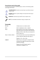
Conventions used in this guide To make sure that you perform certain tasks properly, take note of the following symbols used throughout this manual. DANGER/WARNING: Information to prevent injury to yourself when trying to complete a task. CAUTION: Information to prevent damage to the components when trying to complete a task. IMPORTANT: Instructions that you MUST follow to complete a task. NOTE: Tips and additional information to help you complete a task.
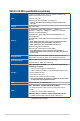
X99-E-10G WS specifications summary LGA2011-v3 socket for Intel® Core™ i7 X-Series / i7 & Xeon® E52600 v4/v3 and 1600 v4/v3 Processors CPU Supports 14nm CPU Supports Intel® Turbo Boost Max Technology 3.0* * The Intel® Turbo Boost Max Technology 3.0 support depends on the CPU types. Chipset Intel® X99 Chipset 8 x DIMM, Max. 128GB, DDR4 3333(O.C.)* / 3200(O.C)* / 3000(O.C)* / 2800(O.C.)* / 2666(O.C.)* / 2400(O.C.)* /2133 MHz Non-ECC, Un-buffered Memory *1 8 x DIMM, Max.
X99-E-10G WS specifications summary Realtek® ALC1150 8-channel high definition audio CODEC featuring Crystal Sound 3 - Separate layer for left and right track, ensuring both sound deliver equal quality - Top notch audio sensation delivers according to the audio configuration - Audio shielding ensures precise analog/digital separation and greatly reduced multi-lateral interference - Audio Amplifier to enhance the highest quality sound for headphone and speakers Audio - Premium Japan-made audio capacito
X99-E-10G WS specifications summary UEFI BIOS - Most Advanced Options with Fast Response Time M.2 and U.2 Onboard - The Latest Transfer Technology with up to 32Gb/s Data-transfer Speeds for M.2 and U.2 Special Memory O.C. Design - Superb Memory O.C.
X99-E-10G WS specifications summary Special Features: - USB 3.1 Boost - Ai Charger+ ASUS Special Features - Disk Unlocker - AI Suite 3 - MemOK! - EZ XMP - 7 PCIe x 16 Slots Workstation Exclusive - ProCool Power Connector - ASUS PIKE SAS upgrade kit (Optional) 2 x USB 3.0/2.0 Connectors Support Additional 4 USB Ports (19pin) 2 x USB 2.0/1.1 Connectors Support Additional 4 USB Ports 1 x M.2 Socket 3 (for M Key, Type 2260/2280 Devices) 1 x U.2 Connector (support U.2 NVMe device) 10 x SATA 6.
X99-E-10G WS specifications summary 4 x USB 3.0/2.0 Ports (blue) 2 x USB 3.1 Ports (Type A and Type C) Rear Panel I/O Ports 1 x Optical S/PDIF Out Port 1 x COM port header 2 x Intel 10G LAN (BASE-T) Ports 8-channel Audio I/O Ports Windows® 10* Operating system Windows® 8.1* Windows® 7* * 64-bit supported only Form Factors CEB Form Factor, 12”x 10.5” (30.5cm x 26.7cm) Specifications are subject to change without notice.
Package contents Check your motherboard package for the following items 10 x Serial ATA 6 Gb/s cables ASUS X99-E-10G WS motherboard 1 x 3-WAY SLI bridge connector 1 x ASUS Q-Shield 1 x 2-in-1 ASUS Q-Connector kit 1 x ASUS SLI® bridge connector COM port bracket 1 x 4-WAY SLI bridge connector 1 x RGB LED extension cable nual User Ma Support DVD User Guide 1 x 2-port USB 2.0 cable • If any of the above items is damaged or missing, contact your retailer.
Installation tools and components Intel® LGA2011-v3 CPU Intel® LGA2011-v3 compatible CPU Fan PC chassis SATA hard disk drive Phillips (cross) screwdriver DIMM 1 bag of screws Power supply unit SATA optical disc drive (optional) Graphics card The tools and components in the table above are not included in the motherboard package.
Chapter 1: Product Introduction Product Introduction 1.1 Special features 1.1.1 Product highlights 1 LGA2011-v3 socket for Intel® Core™ i7 X-Series / i7 processors This motherboard supports Intel® Core™ i7 X-Series / i7 processors in the LGA2011-v3 package. It provides great system performance, quad-channel DDR4 memory slots and PCI Express 2.0/3.0 expansion slots.
Complete USB 3.1 integration This motherboard has the latest USB 3.1 connectivity built in with Type-A and Type-C ports for the very fastest USB data transfers — that’s up to 10 Gb/s, or twice as fast as USB 3.0. The Type-A USB 3.1 port is completely backward compatible with your existing USB devices, and you'll be all set for USB 3.1's breakneck speeds. The Type-C USB 3.1 port is the all new reversible socket for any-way-up convenience. And ASUS-exclusive USB 3.
1.2 Motherboard overview 1.2.1 Before you proceed Take note of the following precautions before you install motherboard components or change any motherboard settings. Unplug the power cord from the wall socket before touching any component. • Before handling components, use a grounded wrist strap or touch a safely grounded object or a metal object, such as the power supply case, to avoid damaging them due to static electricity. • Hold components by the edges to avoid touching the ICs on them.
1.2.2 Motherboard layout Refer to 1.2.9 Internal connectors and 2.3.1 Rear I/O connection for more information about rear panel connectors and internal connectors.
Layout contents Connectors/Jumpers/Buttons and switches/Slots 1. DDR4 DIMM slots 2. ATX power connectors (24-pin EATXPWR; 8-pin EATX12V; 8-pin EATX12V1; 6-pin EATX12V_1) Page 1-7 1-29 3. 4. 1-6 1-28 5. 6. 7. 8. 9. 1-26 1-13 1-14 1-15 1-24 1-12 1-12 2-11 1-33 1-14 1-31 1-32 1-30 1-32 1-27 1-35 1-31 1-34 1-16 1-20 1-33 1-25 1-25 Chapter 1 10. 11. 12. 13. 14. 15. 16. 17. 18. 19. 20. 21. 22. 23. 24 25. 26. 27.
1.2.3 Central Processing Unit (CPU) The motherboard comes with a surface mount LGA2011-v3 socket designed for Intel® Core™ i7 X-Series / i7 processors. • Ensure that all power cables are unplugged before installing the CPU. • Upon purchase of the motherboard, ensure that the PnP cap is on the socket and the socket contacts are not bent. Contact your retailer immediately if the PnP cap is missing, or if you see any damage to the PnP cap/socket contacts/motherboard components.
1.2.4 System memory The motherboard comes with eight (8) DDR 4 (Double Data Rate 4) Quad Inline Memory Modules (DIMM) slots. A DDR4 module is notched differently from a DDR, DDR2, or DDR3 module. DO NOT install a DDR, DDR2, or DDR3 memory module to the DDR4 slot.
Memory configurations You may install 2 GB, 4 GB, 8 GB, and 16GB unbuffered and non‑ECC DDR4 DIMMs into the DIMM sockets. Chapter 1 1-8 • You may install varying memory sizes in Channel A, Channel B, Channel C, and Channel D. The system maps the total size of the lower-sized channel for the dualchannel configuration. Any excess memory from the higher-sized channel is then mapped for single-channel operation. • According to Intel® CPU spec, DIMM voltage below 1.65 V is recommended to protect the CPU.
1.2.5 Expansion slots Unplug the power cord before adding or removing expansion cards. Failure to do so may cause you physical injury and damage motherboard components. Slot Description 1 PCIe 3.0/2.0 x16_1 slot 2 PCIe 3.0/2.0 x16_2 slot 3 PCIe 3.0/2.0 x16_3 slot 4 PCIe 3.0/2.0 x16_4 slot 5 PCIe 3.0/2.0 x16_5 slot 6 PCIe 3.0/2.0 x16_6 slot 7 PCIe 3.0/2.0 x16_7 slot ASUS X99-E-10G WS Chapter 1 Slot No.
PCI Express 3.0 operating mode PCIe 3.0/2.0 x16_1 PCIe 3.0/2.0 x16_2 PCIe 3.0/2.0 x16_3 PCIe 3.0/2.0 x16_4 PCIe 3.0/2.0 x16_5 PCIe 3.0/2.0 x16_6 PCIe 3.0/2.
IRQ assignments for this motherboard A B C D E F G H PCIEX16_1 shared – – – – – – – PCIEX16_2 PCIEX16_3 PCIEX16_4 PCIEX16_5 PCIEX16_6 PCIEX16_7 SMBUS Controller Intel® SATA Controller 1 Intel® SATA Controller 2 Intel® LAN1 (x550) Intel® LAN2 (x550) Intel® xHCI Intel® EHCI 1 Intel® EHCI 2 HD Audio shared – – shared – – shared – – shared – – shared – – shared – – – – shared – shared – – – shared shared – – – shared – – – – shared – – – – – – – – – – – – – – – – – – – – – – – – – – – – – –
1.2.6 Onboard buttons and switches Onboard buttons and switches allow you to fine-tune performance when working on a bare or open-case system. This is ideal for overclockers and gamers who continually change settings to enhance system performance. 1. Power-on button (PWR_SW) The motherboard comes with a power-on button that allows you to power up or wake up the system.
3. MemOK! button (MemOK) • Refer to section 1.2.8 Onboard LEDs for the exact location of the DRAM_LED. • The DRAM_LED also lights up when the DIMM is not properly installed. Turn off the system and reinstall the DIMM before using the MemOK! function. • The MemOK! button does not function under Windows® OS environment. • During the tuning process, the system loads and tests failsafe memory settings. It takes about 30 seconds for the system to test one set of failsafe settings.
4. Clear CMOS button (CLR_CMOS) Press this button to clear the BIOS setup information only when the systems hangs due to overclocking. 5. EZ XMP switch (EZ_XMP) Enable this switch to overclock the installed DIMMs, allowing you to enhance the DIMM’s speed and performance. Chapter 1 The EZ XMP LED (XLED1) lights up when you enable the EZ XMP switch. For the location of the EZ XMP LED, refer to section 1.2.8 Onboard LEDs.
6. SLI/CFX switch (SLI/CFX) This switch allows you to determine the slots for 2-WAY or 3-WAY graphics card installation. When enabled, the PCIE LEDs near the slots light up, telling you to install the graphics cards to the specific slots. We recommend that you insert your graphics cards into PCIEX16_1 and PCIEX16_5 when 2-WAY SLI/Crossfire is enabled. • We recommend that you insert your graphics cards into PCIEX16_1, PCIEX16_3, and PCIEX16_5 when 3-WAY SLI/Crossfire is enabled.
1.2.7 1. Jumpers CPU Over Voltage jumper (3-pin CPU_OV) The CPU Over Voltage jumper allows you to set a higher CPU voltage for a flexible overclocking system, depending on the type of the installed CPU. To gain more CPU voltage setting, insert the jumper to pins 2-3. To go back to its default CPU voltage setting, insert the jumper to pins 1-2.
1.2.8 1. Onboard LEDs Diagnosis LEDs The Diagnosis LEDs provide the status of these key components during POST (PowerOn-Self Test): CPU, VGA card, and hard disk drives. If an error is found, the critical component’s LED stays lit up until the problem is solved. 2. EZ XMP LED (XLED1) Chapter 1 This LED lights up when you enable the EZ XMP switch.
3. DRAM LED (DRAM_LED) The DRAM LED checks DRAM during motherboard booting process. If an error is found, the LED flashes until the problem is solved. 4. USB BIOS Flashback LED (FLBK_LED) The BIOS Flashback LED flashes when you press the BIOS Flashback button for BIOS update.
5. PCIE LEDs The PCIE LEDs light up to indicate which PCIE slots to use when SLI/CFX switch is enabled. 6. SLI/CFX LEDs Chapter 1 The SLI/CFX LEDs light up when SLI/CFX switch is enabled.
7. Q-Code LEDs The Q-Code LED design provides you with a 2-digit error code that displays the system status. Refer to the Q-Code table on the next page for details.
Q-Code table 4F 54 55 56 57 58 59 5A 5B 5C – 5F E0 E1 E2 E3 E4 – E7 E8 E9 EA EB EC – EF F0 F1 F2 F3 F4 F5 – F7 F8 F9 Description Not used microcode CACHE_ENABLED PCH initialization CPU_EARLY_INIT PEI Core is started Pre-memory CPU initialization is started Pre-memory System Agent initialization is started Pre-memory PCH initialization is started Memory initialization Reserved for ASL (see ASL Status Codes section below) Memory Installed CPU post-memory initialization Post-Memory System Agent initializatio
Chapter 1 Code FA FB – FF 60 61 62 63 – 67 68 69 6A 6B – 6F 70 71 72 73 – 77 78 79 7A – 7F 90 91 92 93 94 95 96 97 98 99 9A 9B 9C 9D 9E – 9F A0 A1 A2 A3 A4 A5 A6 A7 A8 A9 AA AB Description Invalid recovery capsule Reserved for future AMI error codes DXE Core is started NVRAM initialization Installation of the PCH Runtime Services CPU DXE initialization is started PCI host bridge initialization System Agent DXE initialization is started System Agent DXE SMM initialization is started System Agent DXE initia
Code AC AD AE AF B0 B1 B2 B3 B4 B5 B6 B7 B8– BF D0 D1 D2 D3 D4 D5 D6 D7 D8 D9 DA DB DC Description Reserved for ASL (see ASL Status Codes section below) Ready To Boot event Legacy Boot event Exit Boot Services event Runtime Set Virtual Address MAP Begin Runtime Set Virtual Address MAP End Legacy Option ROM Initialization System Reset USB hot plug PCI bus hot plug Clean-up of NVRAM Configuration Reset (reset of NVRAM settings) Reserved for future AMI codes CPU initialization error System Agent initializatio
1.2.9 Internal connectors 1. Intel® X99 Serial ATA 6 Gb/s connectors (7-pin SATA6G_12, SATA6G_34, SATA6G_56, SATA6G_78, SATA6G_910) These connectors connect to Serial ATA 6 Gb/s hard disk drives via Serial ATA 6 Gb/s signal cables. If you installed Serial ATA hard disk drives, you can create a RAID 0, 1, 5, and 10 configuration with the Intel® Rapid Storage Technology through the onboard Intel® X99 chipset. • These connectors are set to [AHCI Mode] by default.
2. Digital audio connector (4-1 pin SPDIF_OUT) This connector is for an additional Sony/Philips Digital Interface (S/PDIF) port. Connect the S/PDIF Out module cable to this connector, then install the module to a slot opening at the back of the system chassis. The S/PDIF module is purchased separately. 3.
4. USB 3.0 connectors (20-1 pin USB3_E78, USB3_E910) These connectors allow you to connect a USB 3.0 module for additional USB 3.0 front or rear panel ports. With an installed USB 3.0 module, you can enjoy all the benefits of USB 3.0 including faster data transfer speeds of up to 5 Gb/s, faster charging time for USB-chargeable devices, optimized power efficiency, and backward compatibility with USB 2.0. The USB 3.0 module is purchased separately.
5. USB 2.0 connectors (10-1 pin USB78, USB910) These connectors are for USB 2.0 ports. Connect the USB module cable to any of these connectors, then install the module to a slot opening at the back of the system chassis. These USB connectors comply with USB 2.0 specification that supports up to 48 Mb/s connection speed. DO NOT connect a 1394 cable to the USB connectors.
6. CPU, CPU optional, water pump, chassis, and high amp fan connectors (4-pin CPU_FAN, 4-pin CPU_OPT, 4-pin W_PUMP, 4-pin CHA_FAN1-2, 4-pin H_AMP_ FAN) Connect the fan cables to the fan connectors on the motherboard, ensuring that the black wire of each cable matches the ground pin of the connector. • DO NOT forget to connect the fan cables to the fan connectors. Insufficient air flow inside the system may damage the motherboard components.
7. ATX power connectors (24-pin EATXPWR; 8-pin EATX12V; 8-pin EATX12V1; 6-pin EATX12V_1) These connectors are for ATX power supply plugs. The power supply plugs are designed to fit these connectors in only one orientation. Find the proper orientation and push down firmly until the connectors completely fit. For a fully configured system, we recommend that you use a power supply unit (PSU) that complies with ATX 12 V Specification 2.0 (or later version) and provides a minimum power of 350 W.
8. System panel connector (20-8 pin PANEL) This connector supports several chassis-mounted functions. • System power LED (2-pin PLED) This 2-pin connector is for the system power LED. Connect the chassis power LED cable to this connector. The system power LED lights up when you turn on the system power, and blinks when the system is in sleep mode. • Hard disk drive activity LED (2-pin HDD_LED) This 2-pin connector is for the HDD Activity LED. Connect the HDD Activity LED cable to this connector.
9. TPM connector (20-1 pin TPM) This connector supports a Trusted Platform Module (TPM) system, which securely store keys, digital certificates, passwords and data. A TPM system also helps enhance network security, protect digital identities, and ensures platform integrity. The TPM module is purchased separately. 10. DirectKey connector (2-pin DRCT) Chapter 1 This connector is for the chassis-mounted button that supports the DirectKey function.
11. M.2 (Socket 3) This socket allows you to install an M.2 (NGFF) SSD module. 12. • This socket supports PCIe 3.0 x4 M Key design and type 2260/2280 PCIe storage devices. • This socket supports PCIe mode only. • When M.2 is in use, U.2 will be disabled, and when U.2 is in use, M.2 will be disabled. • When using a 28-lane CPU, only X550 ports will be enabled. M.2 and U.2 ports will be disabled. • The M.2 (NGFF) SSD module is purchased separately. U.2 connector (U.
13. Chassis intrusion connector (4-1 pin CHASSIS) This connector is for a chassis-mounted intrusion detection sensor or switch. Connect one end of the chassis intrusion sensor or switch cable to this connector. The chassis intrusion sensor or switch sends a high-level signal to this connector when a chassis component is removed or replaced. The signal is then generated as a chassis intrusion event. By default, the pin labeled “Chassis Signal” and “Ground” are shorted with a jumper cap.
15. RGB header (4-pin RGB_HEADER) This connector is for RGB LED strips. The RGB header supports 5050 RGB multi-color LED strips (12V/G/R/B), with a maximum power rating of 2A (12V), and no longer than 2 meters. Before you install or remove any component, ensure that the ATX power supply is switched off or the power cord is detached from the power supply. Failure to do so may cause severe damage to the motherboard, peripherals, or components. • Actual lighting and color will vary with LED strip.
16. T_Sensor connector (2-pin T_SENSOR1) This connector is for the thermistor cable that allows you to monitor the temperature of your motherboard’s critical components and connected devices. Chapter 1 The thermistor cable is purchased separately.
Chapter 1 1-36 Chapter 1: Product Introduction
Chapter 2: Basic Installation Basic Installation 2.1 Building your PC system 2 The diagrams in this section are for reference only. The motherboard layout may vary with models, but the installation steps are the same for all models. 2.1.1 Motherboard installation Install the ASUS Q-Shield to the chassis rear I/O panel. 2. Place the motherboard into the chassis, ensuring that its rear I/O ports are aligned to the chassis’ rear I/O panel. Chapter 2 1.
3. Place nine (9) screws into the holes indicated by circles to secure the motherboard to the chassis. Chapter 2 DO NOT overtighten the screws! Doing so can damage the motherboard.
2.1.2 CPU installation Chapter 2 Please note the order in opening/ closing the double latch. Follow the instructions printed on the metal sealing hatch or the illustrations shown below in this manual. The plastic cap will pop up automatically once the CPU is in place and the hatch properly sealed down.
Triangle mark Triangle mark Chapter 2 2-4 Chapter 2: Basic Installation
2.1.3 CPU heatsink and fan assembly installation Apply the Thermal Interface Material to the CPU heatsink and CPU before you install the heatsink and fan, if necessary.
2.1.
2.1.
2.1.
2.1.7 Front I/O Connector HDD LED+ HDD LED- PWR Ground Reset Ground HDD LED To install ASUS Q-Connector HDD LED R SW POWE RESET SW To install USB 2.0 connector To install front panel audio connector AAFP USB 2.0 Chapter 2 To install USB 3.0 connector USB 3.
2.1.
2.2 BIOS update utility USB BIOS Flashback USB BIOS Flashback allows you to easily update the BIOS without entering the existing BIOS or operating system. Simply insert a USB storage device to the USB port (the USB port hole marked in green on the I/O shield) then press the USB BIOS Flashback button for three seconds to automatically update the BIOS. 1. Place the bundled support DVD to the optical drive and install the USB BIOS Flashback Wizard.
6. Wait until the light goes out, indicating that the BIOS updating process is completed. For more BIOS update utilities in BIOS setup, refer to the section 3.11 Updating BIOS in Chapter 3. • Do not unplug portable disk, power system, or press the CLR_CMOS button while BIOS update is ongoing, otherwise update will be interrupted. In case of interruption, please follow the steps again.
2.3 Motherboard rear and audio connections 2.3.1 Rear I/O connection USB BIOS Flashback port Rear panel connectors 1. USB 3.1 Type-A port EA1 (Supports USB 3.1 Boost) 5. USB 3.1 Type-C port EC2 (Supports USB 3.1 Boost) 2. Intel® 10G LAN port (LAN2)* 6. Optical S/PDIF Out port 3. Intel 10G LAN port (LAN1)* 7. Audio I/O ports** 4. USB 3.0 ports 1234 (Supports USB 3.0 Boost) ® * and **: Refer to the tables on the next page for the LAN port LEDs and audio port definitions.
* 10G LAN ports LED indications Activity Link LED Speed LED Status Description Status Description Off No link Off Green Linked Orange 1 Gbps connection Green (Blinking) Data activity Green 100 Mbps connection ACT/LINK LED SPEED LED 10 Gbps connection LAN port You can disable the LAN controllers in BIOS. Due to hardware design, the 10G LAN1 port’s LEDs may continue to blink even when disabled.
2.3.
Connect to 2.1 channel Speakers Connect to 4.1 channel Speakers Connect to 5.
Connect to 7.1 channel Speakers When the DTS UltraPC II function is enabled, ensure to connect the rear speaker to the light blue port. 2.4 Starting up for the first time 1. After making all the connections, replace the system case cover. 2. Ensure that all switches are off. 3. Connect the power cord to the power connector at the back of the system chassis. 4. Connect the power cord to a power outlet that is equipped with a surge protector. 6. Turn on the devices in the following order: a.
BIOS Beep Description One short beep VGA detected Quick boot set to disabled No keyboard detected One continuous beep followed by two short beeps then a pause (repeated) No memory detected One continuous beep followed by three short beeps No VGA detected One continuous beep followed by four short beeps Hardware component failure 7. 2.5 At power on, hold down the key to enter the BIOS Setup. Follow the instructions in Chapter 3.
Chapter 3: BIOS Setup BIOS Setup 3.1 Knowing BIOS 3 The new ASUS UEFI BIOS is a Unified Extensible Interface that complies with UEFI architecture, offering a user-friendly interface that goes beyond the traditional keyboardonly BIOS controls to enable a more flexible and convenient mouse input. You can easily navigate the new UEFI BIOS with the same smoothness as your operating system. The term “BIOS” in this user manual refers to “UEFI BIOS” unless otherwise specified.
3.2 BIOS setup program Use the BIOS Setup to update the BIOS or configure its parameters. The BIOS screen include navigation keys and brief onscreen help to guide you in using the BIOS Setup program. Entering BIOS at startup To enter BIOS Setup at startup, press during the Power-On Self Test (POST). If you do not press , POST continues with its routines. Entering BIOS Setup after POST To enter BIOS Setup after POST: • Press ++ simultaneously.
3.2.1 EZ Mode By default, the EZ Mode screen appears when you enter the BIOS setup program. The EZ Mode provides you an overview of the basic system information, and allows you to select the display language, system performance mode and boot device priority. To access the Advanced Mode, click Exit/Advanced Mode, then select Advanced Mode or press hot key for the advanced BIOS settings. The default screen for entering the BIOS setup program can be changed.
3.2.2 Advanced Mode The Advanced Mode provides advanced options for experienced end-users to configure the BIOS settings. The figure below shows an example of the Advanced Mode. Refer to the following sections for the detailed configurations. To switch from EZ Mode to Advanced Mode, click Advanced Mode or press F7 hotkey.
Menu bar The menu bar on top of the screen has the following main items: My Favorites For saving the frequently-used system settings and configuration. For changing the basic system configuration Main Ai Tweaker For changing the overclocking settings Advanced For changing the advanced system settings Monitor For displaying the system temperature, power status, and changing the fan settings.
Search on FAQ Move your mouse over this button to show a QR code, scan this QR code on your mobile device to connect to the BIOS FAQ web page of the ASUS support website. You can also scan the following QR code: Quick Note (F9) This button above the menu bar allows you to key in notes of the activities that you have done in BIOS. • The Quick Note function does not support the following keyboard functions: delete, cut, copy, and paste. • You can only use the alphanumeric characters to enter your notes.
3.2.3 QFan Control The QFan Control allows you to set a fan profile or manually configure the operating speed of your CPU and chassis fans.
Configuring fans manually Select Manual from the list of profiles to manually configure your fans’ operating speed. Speed points Select to manually configure your fans To configure your fans: 1. Select the fan that you want to configure and to view its current status. 2. Click and drag the speed points to adjust the fans’ operating speed. 3. Click Apply to save the changes then click Exit (ESC).
3.2.4 EZ Tuning Wizard EZ Tuning Wizard allows you to easily overclock your CPU and DRAM, computer usage, and CPU fan to their best settings. You can also set RAID in your system using this feature. OC setup RAID setup OC Tuning To start OC Tuning: 1. Press on your keyboard or click EZ Tuning Wizard screen. 2. Click OC then click Next. 3. Select a PC scenario Daily Computing or Gaming/Media Editing, then click Next.
4. Select a Main Cooling System BOX cooler, Tower cooler, Water cooler, or I’m not sure, then click Next. 5. After selecting the Main Cooling System, click Next then click Yes to start the OC Tuning. Creating RAID To create RAID: 1. Press on your keyboard or click EZ Tuning Wizard screen. 2. Click RAID then click Next. 3. from the BIOS screen to open • Ensure that your HDDs have no existing RAID volumes. • Ensure to connect your HDDs to Intel® SATA connectors.
4. Select the type of storage for your RAID, Easy Backup or Super Speed, then click Next. a. For Easy Backup, click Next then select from Easy Backup (RAID 1) or Easy Backup (RAID 10). You can only select Easy Backup (RAID 10) if you connect four (4) HDDs. For Super Speed, click Next then select from Super Speed (RAID 0) or Super Speed (RAID 5). 5. After selecting the type of RAID, click Next then click Yes to continue the RAID setup. 6.
3.3 My Favorites My Favorites is your personal space where you can easily save and access your favorite BIOS items. My Favorites comes with several performance, power saving, and fast boot related items by default. You can personalize this screen by adding or removing items.
Adding items to My Favorites To add BIOS items: from the BIOS screen to open 1. Press on your keyboard or click Setup Tree Map screen. 2. On the Setup Tree Map screen, select the BIOS items that you want to save in My Favorites screen. Main menu panel Selected shortcut items Submenu panel Delete all favorite items Recover to default favorite items 3. Select an item from main menu panel, then click the submenu that you want to save as or press on your keyboard.
3.4 Main menu The Main menu screen appears when you enter the Advanced Mode of the BIOS Setup program. The Main menu provides you an overview of the basic system information, and allows you to set the system date, time, language, and security settings. Security The Security menu items allow you to change the system security settings. Chapter 3 3-14 • If you have forgotten your BIOS password, erase the CMOS Real Time Clock (RTC) RAM to clear the BIOS password. See section 1.2.
Administrator Password If you have set an administrator password, we recommend that you enter the administrator password for accessing the system. Otherwise, you might be able to see or change only selected fields in the BIOS setup program. To set an administrator password: 1. Select the Administrator Password item and press . 2. From the Create New Password box, key in a password, then press . 3. Confirm the password when prompted. To change an administrator password: 1.
3.5 Ai Tweaker menu The Ai Tweaker menu items allow you to configure overclocking-related items. Be cautious when changing the settings of the Ai Tweaker menu items. Incorrect field values can cause the system to malfunction. The configuration options for this section vary depending on the CPU and DIMM model you installed on the motherboard. Scroll down to display other BIOS items. Ai Overclock Tuner [Auto] Allows you to select the CPU overclocking options to achieve the desired CPU internal frequency.
When the Ai Overclock Tuner is set to [Manual] or [XMP], the following items appear. CPU Strap [Auto] This item is default set to auto for a corresponding BCLK (base clock) frequency adjustment. Manually select a strap value close to the target BCLK frequency for an extreme overclocking. Configuration options: [Auto] [100MHz] [125MHz] [167MHz] [250MHz] The following item appears only when you set the CPU Strap to [100MHz], [125MHz], [167MHz], or [250MHz].
CPU Core Ratio [By Specific Core] This item allows you to set the CPU core ratio limit per core or synchronize automatically to all cores. Configuration options: [Auto] [Sync All Cores] [By Core Usage] [By Specific Core] When the CPU Core Ratio is set to [Sync All Cores], the following item appears: 1-Core Ratio Limit [Auto] Select [Auto] to apply the CPU default Turbo Ratio setting or manually assign a 1-Core Limit value that must be higher than or equal to the 2-Core Ratio Limit.
6-Core Ratio Limit [Auto] Select [Auto] to apply the CPU default Turbo Ratio setting or manually assign a 6-Core Limit value. If you assign a value for 6-Core Ratio Limit, do not set the 1-Core Ratio Limit, 2-Core Ratio Limit, 3-Core Ratio, 4-Core Ratio, and 5-Core Ratio to [Auto]. 7-Core Ratio Limit [Auto] Select [Auto] to apply the CPU default Turbo Ratio setting or manually assign a 7-core ratio limit that must be higher than or equal to the 8-core ratio limit.
Internal PLL Overvoltage [Auto] This item allows you to enable Internal PLL Overvoltage for K-SKU and X-SKU CPUs to get extreme overclocking capability. Configuration options: [Auto] [Disabled] [Enabled] BCLK Frequency : DRAM Frequency Ratio [Auto] [Auto] The BCLK frequency to DRAM frequency ratio will be set to the optimized setting. [100:100] The BCLK frequency to DRAM frequency ratio will be set to 100:100. [100:133] The BCLK frequency to DRAM frequency ratio will be set to 100:133.
DRAM RAS# PRE Time [Auto] Configuration options: [Auto] [1] – [31] DRAM RAS# ACT Time [Auto] Configuration options: [Auto] [1] – [63] DRAM Command Rate [Auto] Configuration options: [Auto] [Timing 1T] – [Timing 3T] Secondary Timings DRAM RAS# to RAS# Delay [Auto] Configuration options: [Auto] [1] – [7] DRAM RAS# to RAS# Delay L [Auto] Configuration options: [Auto] [1] – [7] DRAM REF Cycle Time [Auto] Configuration options: [Auto] [1] – [1023] DRAM Refresh Interval [Auto] Configuration options: [Auto] [1] –
tWWDD [Auto] Configuration options: [Auto] [1] - [7] tRWDR [Auto] Configuration options: [Auto] [1] - [7] tWRDR [Auto] Configuration options: [Auto] [1] - [7] tWRDD [Auto] Configuration options: [Auto] [1] - [7] tRWSR [Auto] Configuration options: [Auto] [1] - [7] tCCD [Auto] Configuration options: [Auto] [1] - [7] tUWRDR [Auto] Configuration options: [Auto] [1] - [3] tRWDR2 [Auto] Configuration options: [Auto] [0] - [31] tRWDD [Auto] Configuration options: [Auto] [0] - [31] tRWSR2 [Auto] Configuration opti
DRAM RTL (CHB D0 R1) [Auto] Configuration options: [Auto] [1] - [127] DRAM RTL (CHB D1 R0) [Auto] Configuration options: [Auto] [1] - [127] DRAM RTL (CHB D1 R1) [Auto] Configuration options: [Auto] [1] - [127] DRAM RTL (CHC D0 R0) [Auto] Configuration options: [Auto] [1] - [127] DRAM RTL (CHC D0 R1) [Auto] Configuration options: [Auto] [1] - [127] DRAM RTL (CHC D1 R0) [Auto] Configuration options: [Auto] [1] - [127] DRAM RTL (CHC D1 R1) [Auto] Configuration options: [Auto] [1] - [127] DRAM RTL (CHD D0 R0) [
DRAM IO-L (CHD D0 R0) [Auto] Configuration options: [Auto] [1] - [255] DRAM IO-L (CHD D0 R1) [Auto] Configuration options: [Auto] [1] - [255] DRAM IO-L (CHD D1 R0) [Auto] Configuration options: [Auto] [1] - [255] DRAM IO-L (CHD D1 R1) [Auto] Configuration options: [Auto] [1] - [255] IO control MC Vref(CHA) [Auto] Configuration options: [Auto] [50] - [99.911] MC Vref(CHB) [Auto] Configuration options: [Auto] [50] - [99.911] MC Vref(CHC) [Auto] Configuration options: [Auto] [50] - [99.
Receiver CMD Pre-emphasis [Auto] Configuration options: [Auto] [0.80] - [2.00] Receiver CMD De-emphasis [Auto] Configuration options: [Auto] [0.80] - [2.00] Transmitter CMD De-emphasis [Auto] Configuration options: [Auto] [0.80] - [2.00] Receiver CLK Pre-emphasis [Auto] Configuration options: [Auto] [1.00] - [2.00] Receiver CLK De-emphasis [Auto] Configuration options: [Auto] [1.00] - [2.00] Transmitter CLK De-emphasis [Auto] Configuration options: [Auto] [1.00] - [2.
DRAM Training MemTest [Auto] This item allows you to enable or disable the memory testing. Configuration options: [Auto] [Disabled] [Enabled] Attempt Fast Boot [Auto] This item allows the portion of the memory reference code to be skipped when possible to increase boot speed. Configuration options: [Auto] [Disabled] [Enabled] Attempt Fast Cold Boot [Auto] This item allows the portion of the memory reference code to be skipped when possible to increase boot speed.
The following item appears only when the CPU VRM Switching Frequency is set to [Manual]. Fixed CPU VRM Switching Frequency (KHz) [500] This item allows you to set a higher frequency for a quicker transient response speed. Use the <+> or <-> to adjust the value. The values range from 300 KHz to 600 KHz with an interval of 50 KHz. DO NOT remove the thermal module when the manual mode is selected. The thermal conditions should be monitored.
CPU Current Capability [Auto] This item provides a total power range for CPU overclocking. A higher value setting provides higher power consumption delivery and extends the overclocking frequency range simultaneously. Configuration options: [Auto] [100%] [110%] [120%] [130%] [140%] Configure higher values when overclocking or under a high CPU loading for extra power support.
Enhanced Intel SpeedStep Technology [Enabled] This item allows the operating system to dynamically adjust the processor voltage and cores frequency which decreases the average power consumption the average heat production. Configuration options: [Disabled] [Enabled] Turbo Mode [Enabled] This item allows you to enable your core processor’s speed to run faster than the base operating frequency when it is below operating power, current and temperature specification limit.
Tweaker’s Paradise PLL Post Divider Adjust [Auto] Set this item to [Enabled] when using a High base clock. Configuration options: [Auto] [Enabled] [Disabled] Internal PLL Voltage Prefix [+] This item allows you to change the voltage prefix. Configuration options: [+] [-] Internal PLL Voltage Step Adjustment [Auto] Increasing this item will help Core and Cache Overclock.
The following item appears only when you set the Fully Manual Mode to [Enabled]. CPU System Agent Voltage [Auto] This item allows you to configure the amount of voltage fed to the system agent of the CPU including the PCI-E controller and the PCU (power control unit). Configuring a high system agent voltage may enhance the overclocking capability. Use the <+> or <-> to adjust the value. The values have an interval of 0.003125V. Configuration options: [Auto] [0.800000] - [2.
CPU Cache Voltage [Auto] Configures the mode of voltage fed to the uncores of the processor. Configuration options: [Auto] [Manual Mode] [Offset Mode] [Adaptive Mode] The following items appear only when you set the CPU Cache Voltage to [Manual Mode]. CPU Cache Voltage Override [Auto] Allows you to configure the CPU cache voltage. Use the <+> or <-> to adjust the value. The values have an interval of 0.001V. Configuration options: [Auto] [0.001] - [1.
DRAM SVID Support [Auto] Set this item to [Disabled] when overclocking. Disable this item to stop the CPU from communicating with the external voltage regulator. Configuration options: [Auto] [Disabled] [Enabled] DRAM Voltage(CHA, CHB) [Auto] This item allows you to configure the voltage for the DRAM on the left. Use the <+> or <-> to adjust the value. The values have an interval of 0.010V. Configuration options: [Auto] [0.800] - [1.
PLL Reference Offset Mode Sign [+] [+] Offset the PLL reference value by a positive value. [–] Offset the PLL reference value by a negative value. PLL Reference Offset Value [Auto] This item allows you to configure the amount of voltage fed to the system agent of the CPU including the PCI-E controller and the PCU(power control unit). Configure a high system agent voltage may enhance the overclocking capability. Use the <+> or <-> to adjust the value.
3.6 Advanced menu The Advanced menu items allow you to change the settings for the CPU and other system devices. Chapter 3 Be cautious when changing the settings of the Advanced menu items. Incorrect field values can cause the system to malfunction.
3.6.1 CPU Configuration The items in this menu show the CPU-related information that the BIOS automatically detects. The items in this menu may vary based on the CPU installed. Scroll up or down to display other BIOS items. Hyper-Threading [ALL] [Enabled] This item allows you to enable or disable the Hyper-Threading for logical processor threads.
Intel Virtualization Technology [Disabled] When set to [Enabled], a VMM can utilize the additional hardware capabilities provided by Vanderpool Technology. Configuration options: [Disabled] [Enabled] Hardware Prefetcher [Enabled] This item allows the CPU to prefetch commands and data in the L2 cache, reduces the DRAM loading time and improves the system performance.
CPU C-states [Auto] This item allows you to set the power saving of the CPU states. Configuration options: [Auto] [Disabled] [Enabled] The following items appear only when you set the CPU C-states to [Enabled]. Enhanced C1 state [Enabled] This item allows your CPU to reduce power consumption when the system is in idle mode. Configuration options: [Disabled] [Enabled] CPU C3 Report [Disabled] This item allows you to disable or enable the CPU C3 report to the operating system.
3.6.3 PCH Storage Configuration While entering Setup, the BIOS automatically detects the presence of SATA devices. The SATA Port items show [Not Installed] if no SATA device is installed to the corresponding SATA port. Scroll up or down to display other BIOS items. Hyper kit Mode [Disabled] Disable this option for M.2 devices. Enable this option for “ASUS Hyper kit” card. Configuration options: [Disabled] [Enabled] S.M.A.R.T.
The following items appear only when you set the SATA Controller 1 Mode Selection to [RAID] or [AHCI]. Support Aggressive Link Power Management [Disabled] This item is designed for LPM (link power management) support with a better energy saving conditions. When set to [Enabled], the hot plug function of SATA ports are disabled.
SATA6G_7(Black) - SATA6G_10(Black) SATA6G_7(Black) - SATA6G_10(Black) [Enabled] This item allows you to enable or disable the selected SATA port. Configuration options: [Disabled] [Enabled] Hot Plug [Disabled] These items allows you to enable or disable SATA Hot Plug Support. Configuration options: [Disabled] [Enabled] 3.6.4 System Agent Configuration DMI Configuration Allows you to configure the DMI settings.
PCIEX16_2 PCIEX16_2 Link Speed [Auto] Allows you to select the operating speed of the PCIEX16_2 speed. Configuration options: [Auto] The system will automatically select the PCIEX16_2 slot speed. [Gen1] The PCIEX16_2 slot will run at PCI-E 1.0 speed. [Gen2] The PCIEX16_2 slot will run at PCI-E 2.0 speed. [Gen3] The PCIEX16_2 slot will run at PCI-E 3.0 speed. PCIEX16_3 PCIEX16_3 Link Speed [Auto] Allows you to select the operating speed of the PCIEX16_3 speed.
PCIEX16_6 Link Speed [Auto] Allows you to select the operating speed of the PCIEX16_6 speed. Configuration options: [Auto] The system will automatically select the PCIEX16_6 slot speed. [Gen1] The PCIEX16_6 slot will run at PCI-E 1.0 speed. [Gen2] The PCIEX16_6 slot will run at PCI-E 2.0 speed. [Gen3] The PCIEX16_6 slot will run at PCI-E 3.0 speed. PCIEX16_7 PCIEX16_7 Link Speed [Auto] Allows you to select the operating speed of the PCIEX16_7 speed.
3.6.5 USB Configuration The items in this menu allow you to change the USB-related features. The Mass Storage Devices item shows the auto-detected values. If no USB device is detected, the item shows None. Intel xHCI Mode [Smart Auto] [Smart Auto] Once the xHCI driver has been detected, the USB 3.0 mode will be supported during both POST and operating system. [Auto] xHCI controller will be enabled and run at USB 3.0 mode when the xHCI driver is installed in the operating system.
EHCI Hand-off [Disabled] This item is set to [Disabled] by default for the EHCI (enhanced host controller interface) support by EHCI drivers in operating systems. [Disabled] Support EHCI by EHCI drivers for operating systems with EHCI support. [Enabled] Support EHCI by BIOS for operating systems without EHCI support. USB Single Port Control This item allows you to enable or disable the individual USB ports. Refer to section 1.2.2 Motherboard layout for the location of the USB ports. 3.6.
3.6.7 Onboard Devices Configuration Scroll up or down to view other BIOS items. HD Audio Controller [Enabled] This item allows you to use the Azalia High Definition Audio Controller Configuration options: [Disabled] [Enabled] The following items appear only when you set the HD Audio Controller to [Enabled].
RGB LED Lighting [On] [Off] LEDs will not light up. [On] LEDs will always light up at the S0(Working), S3(Sleep), and S5(Soft off), but not light up at the S5 state when “Erp Ready” is enabled. RGB LED lighting effects [Auto] This item allows you to set the RGB LED lighting effects.
Change Settings [Auto] Allows you to choose the setting for Super IO device. Configuration options: [Auto] [IO=3F8h; IRQ=4] [IO=2F8h; IRQ=3] [IO=3E8h; IRQ=4] [IO=2E8h; IRQ=3] 3.6.8 APM Configuration ErP Ready [Disabled] This item allows you to switch off some power at S4+S5 or S5 to get the system ready for ErP requirement. When set to [Enabled], all other PME options are switched off.
3.6.9 Network Stack Configuration Network stack [Disabled] This item allows you to disable or enable the UEFI network stack. Configuration options: [Disabled] [Enabled] The following item appears only when you set the Network Stack to [Enabled]. Ipv4/Ipv6 PXE Support [Enabled] This item allows you to enable/disable the Ipv4/Ipv6 PXE wake event. Configuration options: [Disabled] [Enabled] 3.6.10 HDD/SDD SMART Information This menu displays the SMART information of the connected devices.
3.6.11 Intel(R) Ethernet Controller - 00:1E:99:00:01:1B This menu allows you to configure the parameters of the 10 Gigabit Ethernet device NIC Configuration The items in this menu allow you to configure the boot protocol, Wake-on LAN, link speed, and virtual LAN. Link Speed [Auto Negotiated] This item allows you to specify the port speed used for the selected boot protocol.
3.6.12 Intel(R) Ethernet Controller - 00:1E:99:00:01:1C This menu allows you to configure the parameters of the 10 Gigabit Ethernet device NIC Configuration The items in this menu allow you to configure the boot protocol, Wake-on LAN, link speed, and virtual LAN. Link Speed [Auto Negotiated] This item allows you to specify the port speed used for the selected boot protocol.
3.7 Monitor menu The Monitor menu displays the system temperature/power status, and allows you to change the fan settings. Scroll up or down to view other BIOS items. CPU Temperature, Motherboard Temperature, PCIEX16_1 slot Temperature, PCIEX16_3 slot Temperature, VRM Temperature, PCH Temperature, T_ Sensor1 Temperature [xxx°C/xxx°F] The onboard hardware monitor automatically detects and displays the temperatures. Select [Ignore] if you do not wish to display the detected temperatures.
CPU Q-Fan Control [Auto] This item allows you to set the CPU Q-Fan operating mode. [Auto] Detects the type of CPU fan installed and automatically switches the control modes. [PWM Mode] Enables the CPU Q-Fan control feature in PWM mode for 4-pin CPU fan. [DC Mode] Enables the CPU Q-Fan control feature in DC mode for 3-pin CPU fan. [Disabled] Disables the Q-Fan control. The following items appear only when you set the CPU Q-Fan Control to [Auto], [PWM Mode], and [DC Mode].
CPU Fan Middle Duty Cycle(%) Use the <+> or <-> keys to adjust the CPU fan middle duty cycle. The values range from 20% to 100%. CPU Lower Temperature Use the <+> or <-> keys to adjust the lower limit of the CPU temperature. The values range from 20°C to 75°C. The CPU fan will operate at the minimum duty cycle when the CPU temperature is lower than the limit. CPU Fan Min. Duty Cycle(%) Use the <+> and <-> keys to adjust the minimum CPU fan duty cycle. The values range from 20% to 100%.
Chassis Fan 1-2 Profile [Standard] This item allows you to set the appropriate performance level of the chassis fan. [Standard] Sets to [Standard] to make the chassis fan automatically adjust depending on the chassis temperature. [Silent] Sets to [Silent] to minimize the fan speed for quiet chassis fan operation. [Turbo] Sets to [Turbo] to achieve maximum chassis fan speed. [Manual] Sets to [Manual] to assign detailed fan speed control parameters.
The following items appear only when you set the Water Pump Control to [Auto], [PWM Mode], and [DC Mode]. Water Pump Temperature Use the <+> and <-> keys to adjust the upper limit of the water pump. The values range from 45°C to 75°C. The water pump will operate at the maximum duty cycle when the CPU temperature is higher than the limit. Water Pump Max. Duty Cycle(%) Use the <+> and <-> keys to adjust the maximum water pump duty cycle. The values range from 60% to 100%.
HAMP Fan Q-Fan Source [CPU] The assignment fan will be controlled according to the selected temperature source. Configuration options: [CPU] [MotherBoard] [PCIEX16_1 Slot] [PCIEX16_3 Slot] [VRM] [PCH] [T_SENSOR1] [EXT_Sensor1] [EXT_Sensor2] [EXT_Sensor3] [Multiple Sources] • For EXT_Sensor1-3, connect a Thermistor cable to the EXT_TS1-3 header then place the other end to the component to get the temperature.
HAMP Fan Middle. Duty Cycle (%) Use the <+> or <-> keys to adjust the HAMP Fan middle duty cycle. The values range from 60% to 100%. HAMP Fan Lower Temperature Use the <+> or <-> keys to adjust the lower limit of the HAMP Fan temperature. The values range from 20°C to 75°C. The HAMP Fan will operate at the minimum duty cycle when the temperature source is lower than the limit. Anti Surge Support [ON] Enable this item for Over Voltage Protection (OVP) and Under Voltage Protection (UVP) functions.
3.8 Boot menu The Boot menu items allow you to change the system boot options. Scroll up or down to view other BIOS items. Boot Configuration Fast Boot [Enabled] [Disabled] This item allows your system to go back to its normal boot speed. [Enabled] This item allows your system to accelerate the boot speed. The following items appear only when you set the Fast Boot to [Enabled]. SATA Support [All SATA Devices] [Last Boot HDD Only] Only boot drives connected to a SATA ports are detected during POST.
Network Stack Driver Support [Disabled] [Disabled] Select to skip the network stack driver from loading during POST. [Enabled] Select to load the network stack driver during POST. Redirection Support [Disabled] This item allows you to enable or disable redirection support. Configuration options: [Enabled] [Disabled] Next Boot after AC Power Loss [Normal Boot] [Normal Boot] Returns to normal boot on the next boot after an AC power loss.
Above 4G Decoding [Disabled] This item enables or disables 64-bit capable devices to be decoded in above 4G address space if your system supports 64-bit PCI Decoding. Configuration options: [Enabled] [Disabled] Setup Mode [EZ Mode] [Advanced Mode] This item allows you to go to Advanced Mode of the BIOS after POST. [EZ Mode] This item allows you to go to EZ Mode of the BIOS after POST.
OS Type [Windows UEFI mode] [Windows UEFI Mode] Execute the Microsoft secure boot check. Only check this option when booting on Windows UEFI mode or other Microsoft secure boot compliant operating systems. [Other OS] Select this option to get the optimized functions when booting on Windows non-UEFI mode and Microsoft secure boot noncompliant operating systems. The following item appears only when you set the OS Type to [Other OS].
DB Management Delete the db This item allows you to delete the DB from the system. This operation may cause boot failures. Load Default db [Yes] Load the default DB. [No] Load the DB from a USB storage device. Append Default db [Yes] Append the default DB. [No] Append the DB from a USB storage device. UEFI executable files include UEFI boot loaders, drivers, and applications. DBX Management Delete the dbx This item allows you to delete the DBX from the system.
3.9 Tool menu The Tool menu items allow you to configure options for special functions. Select an item then press to display the submenu. Setup Animator [Disabled] This item allows you to enable or disable the Setup animator. Configuration options: [Disabled] [Enabled] 3.9.1 GPU Post This item shows the installed graphics cards in the motherboard. It also suggests the configuration of graphic cards in the motherboard for the best performance. 3.9.
• The time to erase the contents of your SSD may take a while depending on its size. Do not turn off the system during the process. • Secure Erase is only supported on Intel SATA port. For more information about Intel SATA ports, refer to section 1.2.2 Motherboard layout of this manual. Displays the available SSDs Status definition: Frozen. The frozen state is the result of a BIOS protective measure. The BIOS guards drives that do not have password protection by freezing them prior to booting.
3.9.4 ASUS Overclocking Profile This item allows you to store or load multiple BIOS settings. Load from Profile This item allows you to load the previous BIOS settings saved in the BIOS Flash. Key in the profile number that saved your BIOS settings, press , and then select Yes. • DO NOT shut down or reset the system while updating the BIOS to prevent the system boot failure! • We recommend that you update the BIOS file only coming from the same memory/ CPU configuration and BIOS version.
3.9.5 ASUS SPD Information Chapter 3 This item allows you to view the DRAM SPD information.
3.10 Exit menu The Exit menu items allow you to load the optimal default values for the BIOS items, and save or discard your changes to the BIOS items. You can access the EZ Mode from the Exit menu. Load Optimized Defaults This option allows you to load the default values for each of the parameters on the Setup menus. When you select this option or if you press , a confirmation window appears. Select OK to load the default values.
3.11 Updating BIOS The ASUS website publishes the latest BIOS versions to provide enhancements on system stability, compatibility,and performance. However, BIOS updating is potentially risky. If there is no problem using the current version of BIOS, DO NOT manually update the BIOS. Inappropriate BIOS updating may result to system’s failure to boot. Carefully follow the instructions in this chapter to update your BIOS when necessary. Visit http://www.asus.
3.11.2 ASUS EZ Flash 3 ASUS EZ Flash 3 allows you to download and update to the latest BIOS through the Internet without having to use a bootable floppy disk or an OS‑based utility. Updating through the Internet varies per region and Internet conditions. Check your local Internet connection before updating through the Internet. To update the BIOS by USB: 1. Enter the Advanced Mode of the BIOS setup program. Go to the Tool menu to select ASUS EZ Flash Utility and press . 2.
• This function can support devices such as a USB flash disk with FAT 32/16 format and single partition only. • DO NOT shut down or reset the system while updating the BIOS to prevent system boot failure! Ensure to load the BIOS default settings to ensure system compatibility and stability. Select the Load Optimized Defaults item under the Exit menu. See section 3.10 Exit Menu for details. 1. Enter the Advanced Mode of the BIOS setup program.
3.11.3 ASUS CrashFree BIOS 3 The ASUS CrashFree BIOS 3 utility is an auto recovery tool that allows you to restore the BIOS file when it fails or gets corrupted during the updating process. You can restore a corrupted BIOS file using the motherboard support DVD or a USB flash drive that contains the BIOS file. The BIOS file in the motherboard support DVD may be older than the BIOS file published on the ASUS official website. If you want to use the newer BIOS file, download the file at https://www.asus.
Chapter 4: Software Support Software Support 4.1 Installing an operating system 4.2 4 • This motherboard supports 32-bit/64-bit Windows® 7, 32-bit/64-bit Windows® 8.1, and 32-bit/64-bit Windows ®10 operating systems (OS). • Motherboard settings and hardware options vary. Use the setup procedures presented in this chapter for reference only. Refer to your OS documentation for detailed information.
Support DVD main menu Shows the available device drivers if the system detects installed devices. Install the necessary drivers to use the devices. Click to display the applications and other software that the motherboard supports Contains the list of supplementary user manuals.
4.3 Software information Most of the applications in the support DVD have wizards that will conveniently guide you through the installation. View the online help or readme file that came with the software application for more information. 4.4 AI Suite 3 AI Suite 3 is an all-in-one interface that integrates several ASUS utilities and allows you to launch and operate these utilities simultaneously.
Windows® 8.1 / Windows® 10 OS 1. Place the Support DVD into the optical drive then follow onscreen instructions. 2. From the ASUS motherboard support DVD main menu, select the Utilities tab and check AI Suite 3 and select Install. 3. Follow the succeeding onscreen instructions. If the ASUS motherboard support DVD main menu did not appear, try the following steps: a. Go to the Start Screen then click the Desktop app. b.
AI Suite 3 Main menu The AI Suite 3 main menu gives you easy-access controls and insight to what’s going on with your computer - allowing you to optimize performance settings while at the same time ensuring system stability. The AI Suite main menu includes is a quick-access menu bar that allows you to swiftly launch any of the integrated ASUS utilities. Click on the left of the menu to launch the menu bar.
AI Suite 3 mini-menu The AI Suite 3 mini-menu appears on the desktop and can be conveniently accessed and moved around. The AI Suite 3 mini-menu allows you to quickly access the important items in the AI Suite 3.
4.4.1 Dual Intelligent Processors 5 ASUS Dual Intelligent Processors 5 combines TPU, EPU, DIGI+ Power Control, Fan Xpert 4, and Turbo App functions to push the system’s performance to its optimal potential. It automatically balances the system’s performance, power saving, levels, and fan settings via the user-friendly AI Suite 3 utility. 5-Way Optimization The 5-Way Optimization function dynamically optimizes your PC based on real-time usage to provide the best system status.
4.4.2 TPU (Turbo Processing Unit) TPU allows you to manually adjust the CPU frequency, core ratio, DRAM frequency, and related voltages for enhanced system stability and performance boost. Refer to the CPU documentation before adjusting CPU voltage settings. Setting a high voltage may damage the CPU permanently and setting a low voltage may lead to an unstable system. For system stability, the TPU settings are not saved in the BIOS and are not loaded during system bootup.
CPU Strap This item allows you to adjust the CPU Strap’s BLCK (Base Clock) frequency. Adjust the BCLK frequency 4.4.3 Turbo App Turbo App allows you customize the system performance, network priority, and audio setting of an application. When an application is on the Turbo App List, you can allocate the CPU frequency, assign a network priority, and define the audio setting of the selected application. Launching Turbo App on your computer To launch Turbo App, click or tap then select Turbo App.
4.4.4 EPU (Energy Processing Unit) EPU is a real-time system power-saving chip that automatically detects the current system load and intelligently moderates power usage. It offers a total system-wide energy optimization, reduces fan noise, and extends the lifespan of your hardware components. Launching EPU on your computer To launch EPU, click or tap select EPU.
4.4.5 Fan Xpert 4 ASUS Fan Xpert 4 provides customizable settings of your fans for a cooler and quieter computing environment. With its fan Auto Tuning feature, ASUS Fan Xpert 4 automatically tweaks the settings of CPU and chassis fans to achieve their best cooling performance. ASUS Fan Xpert 4 also supports hardware level PWM/DC combo mode for the CPU, chassis fans, and fans connected to the fan extension card.
RPM Mode RPM Mode allows you to set the fan speed when the CPU temperature is below 75oC. Click and drag to adjust the Click to switch between the fan’s speed CPU and chassis fan screens 4.4.6 • When the CPU temperature reaches 75oC, the fan will automatically run at full speed to protect the CPU. • The Fan Xpert 4 may not be able to detect the fan speed if your fan is installed with an external control kit for rotation speed. • Fan Xpert 4 does not support 2-pin fans.
4.4.7 DIGI+ Power Control ASUS DIGI+ Power Control features the revolutionary and innovative digital VRM and DRAM Voltage controllers. These controllers offers ultra-precise memory and voltage tuning for optimal system efficiency, stability and performance. The following screens are for reference only. Configuration options varies depending on the motherboard model. Launching DIGI+ Power Control on your computer To launch DIGI+ Power Control, click or tap menu, then select DIGI+ Power Control.
CPU Power Duty Control CPU Power Duty Control adjusts the current of every VRM phase and the thermal conditions of every phase component. Active Frequency Mode Active Frequency Mode allows you to enhance the power saving condition of the CPU. Click ON to get a quicker transient response while saving the CPU power.
4.4.8 Ai Charger+ Ai Charger+ allows you to fast-charge your portable BC 1.1* mobile devices on your computer’s USB port three times faster than the standard USB devices**. Ai Charger+ is available only in selected motherboard models. Launching Ai Charger+ on your computer To launch Ai Charger+, click or tap then select Ai Chager+.
4.4.9 USB 3.1 Boost USB 3.1 Boost technology supports UASP (USB Attached SCSI Protocol) that automatically speeds up the transfer rates of your USB storage devices. Launching USB 3.1 Boost on your computer To launch USB 3.1 Boost, click or tap then select USB 3.1 Boost. on the top-right corner of the AI Suite 3 main menu, Using the USB 3.
4.4.10 EZ Update EZ Update is a utility that allows you to automatically update your motherboard’s software, drivers, or BIOS. With this utility, you can also manually update the BIOS and select the boot logo that will display during POST. Launching EZ Update on your computer To launch EZ Update, click or tap then select EZ Update.
4.4.11 System Information This utility displays the detailed information and settings of the installed motherboard, CPU, and memory. Launching System Information on your computer To launch System Information, click or tap menu, then select System Information. on the top-right corner of the AI Suite 3 main Viewing the motherboard information Click the MB tab to view the motherboard’s information. Viewing the CPU information Click the CPU tab to view the processor’s information.
Viewing the SPD information Click the SPD tab to view the memory’s information. 4.4.12 Mobo Connect Mobo Connect allows you to share the PC’s keyboard/mouse for smart devices, or stream audio playback from your smart device yo the PC. Launching Mobo Connect on your computer To launch Mobo Connect, click or tap then select Mobo Connect.
4.4.13 USB BIOS Flashback USB BIOS Flashback allows you to check and save the latest BIOS version to a USB storage device. Use this utility to quickly check for the latest available BIOS and set the BIOS download schedule. Launching USB BIOS Flashback on your computer To launch USB BIOS Flashback, click or tap menu, then select USB BIOS Flashback. on the top-right corner of the AI Suite 3 main USB BIOS Flashback is available only in selected motherboard models.
Downloading the latest BIOS Before you start downloading, ensure that you have installed the USB storage device to your computer’s USB port that supports USB BIOS Flashback. Refer to section 2.3.1 Rear I/O connection of this user guide for more details. To download the updated BIOS: 1. From the USB BIOS Flashback screen, Click Check for New BIOS Update. Wait for the system to check the latest BIOS version.
4.4.14 Push Notice This utility allows you get the detailed status of your system to your smart device. You can also send messages to your smart device using this utility. Before using this utility, ensure that you pair your computer with your smart device. For pairing information, refer to section Pairing your computer and smart device. Launching Push Notice on your computer To launch Push Notice, click or tap then select Push Notice.
Setting up PC Mode alerts of your computer This feature allows you to restart, shut down, or put your computer to sleep mode and sends an alert to your smart device.
Sending messages to your smart device This feature allows you to send messages to your smart device. You can also send messages via the Push Notice messaging shortcut on the lower-right corner of your screen. To do this, click or tap << then click or tap then select . Tick to select the smart device Click or tap to send your message Click or tap to key in your message Viewing your computer status on your smart device Tap on your smart device to launch Push Notice.
4.5 Audio configurations The Realtek® audio CODEC provides 8-channel audio capability to deliver the ultimate audio experience on your computer. The software provides Jack-Sensing function, S/PDIF Out support, and interrupt capability. The CODEC also includes the Realtek® proprietary UAJ® (Universal Audio Jack) technology for all audio ports, eliminating cable connection errors, and giving users plug and play convenience.
Selecting an audio output Realtek HD Audio Manager allows you to select the type of audio output depending on the output device that you are using. To select an audio output: 1. Insert the audio device’s jack to the Line Out (lime) port. If the audio device’s jack on the Realtek HD Audio is already inserted to the corresponding port, Click Manager. 2. On the pop-up window, tick the audio device that you plugged to the Line Out port then Click Next. a.
Chapter 5: RAID Support RAID Support 5 Windows® 10 32-bit does not support RAID. 5.1 RAID configurations The motherboard comes with the Intel® Rapid Storage Technology that supports RAID 0, RAID 1, RAID 10, and RAID 5 configuration. If you want to install a Windows® operating system to a hard disk drive included in a RAID set, you have to create a RAID driver disk and load the RAID driver during OS installation. Refer to section 5.2 Creating a RAID driver disk for details. 5.1.
5.1.2 Installing Serial ATA hard disks The motherboard supports Serial ATA hard disk drives. For optimal performance, install identical drives of the same model and capacity when creating a disk array. To install the SATA hard disks for a RAID configuration: 1. Install the SATA hard disks into the drive bays. 2. Connect the SATA signal cables. 3. Connect a SATA power cable to the power connector on each drive. 5.1.
5.1.4 Intel® Rapid Storage Technology Option ROM utility To enter the Intel® Rapid Storage Technology Option ROM utility: 1. Turn on the system. 2. During POST, press + to display the utility main menu. RAID Volumes: None defined. Physical Devices: Port Device Model 0 ST3160812AS 1 ST3160812AS 2 ST3160812AS 3 ST3160812AS Serial # 9LS0HJA4 9LS0F4HL 3LS0JYL8 9LS0BJ5H Size 149.0GB 149.0GB 149.0GB 149.
Creating a RAID set To create a RAID set: 1. From the utility main menu, select 1. Create RAID Volume and press . The following screen appears: Name: Volume 0 RAID Level: aaaaaaaaaaaaaaa Disks: dssdsdsds Strip Size:aaaaaaaaaaaaaaaa Capacity:aaaaaaaaaaaaaa Sync:aaaaaaaaaa Create volume [HELP] Enter a unique volume name that has no special characters and is 16 characters or less. 2. Enter a name for the RAID set and press . 3.
5. Use the up/down arrow key to select a drive, and then press to select. A small triangle marks the selected drive. Press after completing your selection. 6. Use the up/down arrow key to select the strip size for the RAID array (for RAID 0, 10 and 5 only),and then press . The available strip size values range from 4KB to 128KB.
Deleting a RAID set Be cautious when deleting a RAID set. You will lose all data on the hard disk drives when you delete a RAID set. To delete a RAID set: 1. From the utility main menu, select 2. Delete RAID Volume and press . The following screen appears: Name Volume0 [DELETE VOLUME MENU] Level Drives RAID0 (Stripe) 2 Capacity 298.0GB Status Normal Bootable Yes [HELP] Deleting a volume will reset the disks to non-RAID. WARNING: ALL DISK DATA WILL BE DELETED.
Exiting the Intel® Rapid Storage Technology Option ROM utility To exit the utility: 1. From the utility main menu, select 5. Exit, then press . The following warning message appears: [CONFIRM EXIT] Are you sure you want to exit? (Y/N): 2. Press to exit or press to return to the utility main menu. 5.2 Creating a RAID driver disk 5.2.1 Creating a RAID driver disk in Windows® To install the RAID driver for Windows® OS: 1.
Chapter 5 5-8 Chapter 5: RAID Configurations
Chapter 6: Multi GPU Support Multiple GPU Support 6.1 AMD® CrossFireX™ technology 6 The motherboard supports the AMD® CrossFireX™ technology that allows you to install multi-graphics processing units (GPU) graphics cards. Follow the installation procedures in this section. 6.1.1 Requirements • In Dual CrossFireX mode, you should have two identical CrossFireX-ready graphics cards or one CrossFireX-ready dual-GPU graphics card that are AMD® certified.
6.1.3 Installing two CrossFireX™ graphics cards The following pictures are for reference only. The graphics cards and the motherboard layout may vary with models, but the installation steps remain the same. To install two CrossFire™ graphics cards: 1. Prepare two CrossFireX-ready graphics cards. 2. Insert the two graphics card into the PCIEX16 slots.
5. Connect two independent auxiliary power sources from the power supply to the two graphics cards separately. 6. Connect a VGA or a DVI cable to the graphics card. 6.1.4 Installing three CrossFireX™ graphics cards 1. Prepare three CrossFireX-ready graphics cards. 2. Insert the three graphics card into the PCIEX16 slots.
6.1.5 Installing four CrossFireX™ graphics cards To install four CrossFire™ graphics cards: 1. Prepare four CrossFireX-ready graphics cards. 2. Insert the four graphics cards into the PCIEX16 slots. Refer to Chapter 1 in this user manual for the locations of the PCIEX16 slots recommended for multi-graphics card installation. 3. Ensure that the cards are properly seated on the slots. 4. Align and firmly insert the three CrossFireX bridge connectors to the goldfingers on each graphics card.
6.1.6 Installing the device drivers Refer to the documentation that came with your graphics card package to install the device drivers. Ensure that your PCI Express graphics card driver supports the AMD® CrossFireX™ technology. Download the latest driver from the AMD website at www.amd.com. 6.1.7 Enabling the AMD® CrossFireX™ technology After installing your graphics cards and the device drivers, enable the CrossFireX™ feature through the AMD Vision Engine Control Center in Windows environment.
Enabling Dual CrossFireX™ technology To enable Dual CrossFire™ technology: 1. In the AMD Vision Engine Control Center window, click Performance > AMD CrossFireX™. 2. Select Enable CrossFireX™. 3. Select a GPU combination from the drop-down list. 4. Click Apply to save and activate the GPU settings made.
6.2 NVIDIA® SLI® technology The motherboard supports the NVIDIA® SLI® (Scalable Link Interface) technology that allows you to install multi-graphics processing units (GPU) graphics cards. Follow the installation procedures in this section. 6.2.1 Requirements • In SLI mode, you should have two identical SLI-ready graphics cards that are NVIDIA® certified. • Ensure that your graphics card driver supports the NVIDIA SLI technology. Download the latest driver from the NVIDIA website at www.nvidia.com.
4. Align and firmly insert the SLI bridge connector to the goldfingers on each graphics card. Ensure that the connector is firmly in place. 5. Connect two independent auxiliary power sources from the power supply to the two graphics cards separately. 6. Connect a VGA or a DVI cable to the graphics card. SLI bridge Goldfingers 6.2.3 Installing three SLI-ready graphics cards Refer to the documentation that came with your graphics card package to install the device drivers.
4. Align and firmly insert the 3-way SLI bridge connector to the goldfingers on each graphics card. Ensure that the connector is firmly in place. 5. Connect three independent auxiliary power sources from the power supply to the three graphics cards separately. 6. Connect a VGA or a DVI cable to the graphics card. 6.2.4 3-way SLI bridge Installing four SLI-ready graphics cards To install four SLI-ready graphics cards: 1. Prepare four SLI-ready graphics cards. 2.
6.2.5 Installing the device drivers Refer to the documentation that came with your graphics card package to install the device drivers. Ensure that your PCI Express graphics card driver supports the NVIDIA® SLI® technology. Download the latest driver from the NVIDIA website at www.nvidia.com. 6.2.6 Enabling the NVIDIA® SLI® technology After installing your graphics cards and the device drivers, enable the SLI feature in NVIDIA® Control Panel under the Windows® 7 operating system.
B2. From the Screen Resolution window, click Advanced settings. B3. The NVIDIA Control Panel window appears. Enabling SLI settings Chapter 6 From the NVIDIA Control Panel window, select Configure SLI, Surround, PhysX. In the Quad-SLI enabled, click Maximize 3D Performance SLI to set the display for viewing SLI rendered content. When done, click Apply.
Chapter 6 6-12 Chapter 6: Multiple GPU Support
Appendix Appendix X99-E-10G WS block diagram 40-lane CPU Appendix 28-lane CPU ASUS X99-E-10G WS A-1
Notices Federal Communications Commission Statement This device complies with Part 15 of the FCC Rules. Operation is subject to the following two conditions: • This device may not cause harmful interference. • This device must accept any interference received including interference that may cause undesired operation. This equipment has been tested and found to comply with the limits for a Class B digital device, pursuant to Part 15 of the FCC Rules.
Compliance Statement of Innovation, Science and Economic Development Canada (ISED) This device complies with Innovation, Science and Economic Development Canada licence exempt RSS standard(s). Operation is subject to the following two conditions: (1) this device may not cause interference, and (2) this device must accept any interference, including interference that may cause undesired operation of the device.
REACH Complying with the REACH (Registration, Evaluation, Authorisation, and Restriction of Chemicals) regulatory framework, we published the chemical substances in our products at ASUS REACH website at http://csr.asus.com/english/REACH.htm. DO NOT throw the motherboard in municipal waste. This product has been designed to enable proper reuse of parts and recycling.
FCC Bluetooth Wireless Compliance The antenna used with this transmitter must not be co-located or operated in conjunction with any other antenna or transmitter subject to the conditions of the FCC Grant. Bluetooth Industry Canada Statement This Class B device meets all requirements of the Canadian interference-causing equipment regulations. Cet appareil numérique de la Class B respecte toutes les exigences du Règlement sur le matériel brouilleur du Canada.
Appendix English ASUSTeK Computer Inc. hereby declares that this device is in compliance with the essential requirements and other relevant provisions of related Directives. Full text of EU declaration of conformity is available at: www.asus.com/support Français AsusTek Computer Inc. déclare par la présente que cet appareil est conforme aux critères essentiels et autres clauses pertinentes des directives concernées.
ASUS contact information ASUSTeK COMPUTER INC. Address Telephone Fax Web site 4F, No. 150, Li-Te Road, Peitou, Taipei 112, Taiwan +886-2-2894-3447 +886-2-2890-7798 https://www.asus.com Technical Support Telephone +86-21-38429911 Fax +86-21-5866-8722, ext. 9101# Online support https://www.asus.
DECLARATION OF CONFORMITY Per FCC Part 2 Section 2. 1077(a) Asus Computer International Responsible Party Name: 800 Corporate Way, Fremont, CA 94539. Address: Phone/Fax No: (510)739-3777/(510)608-4555 hereby declares that the product Product Name : Motherboard Model Number : X99-E-10G WS Conforms to the following specifications: FCC Part 15, Subpart B, Unintentional Radiators Supplementary Information: This device complies with part 15 of the FCC Rules.