Motherboard X99-M WS/SE
J12541 改訂版 V2 2017年2月 Copyright © 2017 ASUSTeK COMPUTER INC. All Rights Reserved. 本書およびそれに付属する製品は著作権法により保護されており、その使用、複製、頒布および 逆コンパイルを制限するライセンスのもとにおいて頒布されます。購入者によるバックアップ目 的の場合を除き、ASUSTeK Computer Inc.
もくじ 安全上のご注意.................................................................................................................vi このマニュアルについて....................................................................................................vii X99-M WS/SE仕様一覧.....................................................................................................ix Chapter1 1.1 1.2 1.1.1 製品の特長..........................................................................................................1-1 1.1.
Chapter3 3.1 3.2 UEFI BIOS Utility............................................................................................. 3-2 3.2.1 EZ Mode...............................................................................................................3-3 3.2.2 Advanced Mode................................................................................................3-4 3.2.3 Q-Fan Control.....................................................................................................3-7 3.
4.3 ソフトウェア情報............................................................................................. 4-4 4.4 ユーティリティ................................................................................................... 4-4 4.5 4.4.1 Ai Charger+.........................................................................................................4-7 4.4.2 USB 3.1 Boost.....................................................................................................4-8 4.4.3 EZ Update........
安全上のご注意 電気の取り扱い ・ 本製品、周辺機器、ケーブルなどの取り付けや取り外しを行う際は、必ずコンピューターと周辺 機器の電源ケーブルをコンセントから抜いて行ってください。お客様の取り付け方法に問題が あった場合の故障や破損に関して弊社は一切の責任を負いません。 ・ 電源延長コードや特殊なアダプターを用いる場合は専門家に相談してください。これらは、回 路のショート等の原因になる場合があります。 ・ ご使用の電源装置に電圧選択スイッチが付いている場合は、システムの損傷を防ぐために電 源装置の電圧選択スイッチがご利用の地域の電圧と合致しているかをご確認ください。 ご利用 になる地域の電圧が不明な場合は、各地域の電力会社にお問い合わせください。 ・ 電源装置が故障した場合はご自分で修理・分解をせず、各メーカーや販売店にご相談ください。 ・ 光デジタルS/PDIFは、光デジタルコンポーネントで、クラス1レーザー製品に分類されていま す。 (本機能の搭載・非搭載は製品仕様によって異なります) 不可視レーザー光です。ビームを直接見たり触れたりしないでください。 操作上の注意 ・ 作業を行う前
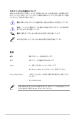
このマニュアルについて このマニュアルには、マザーボードの取り付けやシステム構築の際に必要な情報が記してあります。 マニュアルの概要 本書は以下のChapter から構成されています。 • Chapter 1: 製品の概要 マザーボードの機能とサポートする新機能についての説明、及びスイッチ、ボタン、ジャン パー、コネクター、LEDなど各部位の説明。 • Chapter 2: 基本的な取り付け コンピューターの組み立て方やUSB BIOS Flashbackの使用方法、バックパネルについて の説明。 • Chapter 3: UEFI BIOS 設定 UEFI BIOS Utilityでのシステム設定の変更方法とパラメータの詳細。 • Chapter 4: ソフトウェア マザーボードパッケージに付属のサポートDVDとソフトウェアの内容。 • Chapter 5: RAID RAID 設定についての説明。 • Chapter 6: マルチGPUテクノロジー AMD CrossFireX™ とNVIDIA® SLI™ の複数ビデオカードの取り付けと設定方法の説明。 • Chapter
このマニュアルの表記について 本書には、製品を安全にお使いいただき、お客様や他の人々への危害や財産への損害を未然に 防止していただくために、守っていただきたい事項が記載されています。次の内容をよくご理解 いただいた上で本文をお読みください。 警告: 作業人が死亡する、または重傷を負う可能性が想定される内容を示しています。 意: ハードウェアの損傷やデータの損失の可能性があることを示し、その危険を回 注 避するための方法を説明しています。 重要: 作業を完了するために必要な指示や設定方法を記載しています。 メモ: 製品を使いやすくするための情報や補足の説明を記載しています。 表記 太字 選択するメニューや項目を表示します。 斜字 文字やフレーズを強調する時に使います。 < > で囲った文字は、キーボードのキーです。 例: →Enter もしくはリターンキーを押してください。 一度に2つ以上のキーを押す必要がある場合は(+)を使って示し ています。 例:
X99-M WS/SE仕様一覧 対応CPU LGA2011-v3 ソケット: * Intel® Core™ i7 プロセッサー Intel® Xeon® プロセッサー E5-2600/1600 v3 製品ファミリー 22nm CPU サポート Intel® Turbo Boost Technology 2.0 サポート ** * Intel® Turbo Boost Technology 2.0のサポートはCPUにより異なります。 搭載チップセット Intel® X99 Express チップセット 対応メモリー DDR4 DIMM スロット×4 Non-ECC Unbuffered DIMM: 最大64GB DDR4 3200(O.C.) / 2800(O.C.) / 2666(O.C.) / 2400(O.C.
X99-M WS/SE仕様一覧 LAN機能 デュアルギガビットLANコントローラー - Intel® Ethernet Connection I218-LM - Intel® Ethernet Controller I210-AT オーディオ機能 Realtek® ALC1150(7.
X99-M WS/SE仕様一覧 ASUS独自機能 M.2 対応 * - 最大10Gb/sの転送速度を実現する最新のインターフェース規格 に対応 * 本製品のM.2スロットは、PCIeインターフェース/SATAインターフェースをサポート します。 独自のオーバークロックメモリー設計 - 独自の設計によりカップリングノイズと信号反射を最小限に抑え ることでオーバークロックなどの高負荷時の安定した動作を提供 ASUS Media Streamer <ゲーム特化機能> Turbo APP - 使用中のアプリケーションに基づきシステムパフォーマンスを自 動切り替え Turbo LAN - 低PINGの遅延フリーオンラインゲーム環境を提供 Crystal Sound 2 - 最高のサウンド環境でゲームをより楽しくする <自作支援機能> Push Notice - PCの状態をスマートデバイスに通知 USB BIOS Flashback - CPUやメモリーが不要のUEFI更新機能 UEFI BIOS - 直感的に操作できるグラフィカルなインターフェース - OC.
X99-M WS/SE仕様一覧 ASUS独自機能 USB 3.1 Boost Ai Suite 3 MemOK! EZ XMP USB Charger+ Ai Charger+ Disk Unlocker ワークステーションの 特殊機能 ASUS PIKE SAS upgrade kit(別売)に対応 12k (12000時間) 長寿命コンデンサー ProCool 電源コネクター 基板上 インターフェース USB 3.0コネクター×1 USB 2.0コネクター×2 M.
パッケージの内容 製品パッケージに以下のものが揃っていることを確認してください。 X99-M WS/SEマザーボード Q-Shield×1 SATA 6Gb/s ケーブル×8 シリアルポートブラケット ×1 2-in-1 Q-Connector kit×1 USB 2.
取り付け工具とコンポーネント Intel® LGA2011-v3 対応 CPUクーラー PC ケース 電源供給ユニット SATA光学ドライブ SATAストレージドライブ 各種取付用ネジ Intel® LGA2011-v3 CPU プラスドライバー DDR4 SDRAMメモリー ビデオカード 上記の工具とコンポーネントはマザーボードのパッケージには同梱されていません。 xiv
Chapter1 製品の概要 製品の概要 1.1 特別な機能 1.1.1 製品の特長 1 LGA 2011-v3ソケット Intel® Core™ i7 プロセッサー対応 本製品は、LGA2011-v3パッケージのIntel® Core™ i7 プロセッサーとIntel® Xeon® プロセッサー E52600/1600 v3 製品ファミリーをサポートしています。 これらのプロセッサーはクアッドチャンネルに よるDDR4メモリーコントロールとPCI Express 3.
USB 3.1 ポート搭載 本製品にはUSB 3.0 規格の2倍となる最大10Gbps(理論値) という高速データ転送を実現する、USB3.1 規格のType-A/Type-Cポートが搭載されています。USB 3.1は、USB 3.0 やUSB 2.0 といった従来の USB規格との下位互換性が維持されています。 1.1.2 その他機能 DTS Connect DTS Connect は、DTS Neo: PC™ とDTS Interactive™ の2つのテクノロジーを組み合わせ、臨場感 あるオーディオ体験を提供します。DTS Connect では、高度なアップミキシング技術を使用する ことにより、お気に入りのステレオ音楽やビデオをより良い音で楽しむことができます。また、DTS Connect により、多くのAV機器で使用可能な高品質デジタル・オーディオ接続で、PCをホームシ アター・システムと接続することができます。 「DTS Neo: PC™」は、従来のステレオ音源(CD、mp3、wma、インターネットFMラジオでさえも)を 高品質な7.
1.2 マザーボードの概要 1.2.
1.2.2 マザーボードのレイアウト バックパネルコネクターと内部コネクターの詳細については、 「1.2.9 内部コネクター/ヘッダー」 と 「2.4.
レイアウトの内容 名称 ページ 1. 1-7 DDR4 DIMM スロット 2. ATX電源コネクター (24ピン EATXPWR、8ピン EATX12V、8ピン EATX12V1、6ピン EATX12V_1) 1-30 3. CPU、CPUオプション、ケースファン コネクター (4ピン CPU_FAN、4ピン CPU_OPT、4ピン CHA_FAN1-3) 1-29 4. EPU スイッチ (EPU) 1-19 5. TPU スイッチ (TPU) 1-18 6. リセットボタン (RST_SW) 1-12 7. 電源ボタン (PWR_SW) 1-12 8. EZ XMPスイッチ (EZ_XMP) 1-16 9. USB 3.0コネクター (20-1ピン USB3_56) 1-27 1-25 11. ケース開閉検出コネクター (4-1ピン CHASSIS) 1-34 12. Clear CMOS ボタン (CLR_CMOS) 1-16 13. DirectKeyヘッダー(2ピン DRCT) 1-32 14.
1.2.
1.2.
メモリー構成 本製品のメモリースロットには、2GB、4GB、8GB、16GBのDDR4 ECC Registered / Non-ECC Unbuffered DIMMをメモリースロットに取り付けることができます。 ・ ECC メモリーはIntel® Xeon® E5-1600 v3/2600 v3 プロセッサー使用時のみサポートします。 ・ Registered DIMMとUnbuffered DIMMの混在搭載はできません。 • 容量の異なるメモリーを Channel A / B / C / Dに取り付けることができます。異なる容量 のメモリーをクアッドチャンネル構成で取り付けた場合、アクセス領域はメモリー容量の 合計値が小さい方のチャンネルに合わせて割り当てられ、容量の大きなメモリーの超過 分に関してはシングルチャンネル用に割り当てられます。 • CPUの仕様電圧範囲以上の高い電圧を必要とするメモリーを取り付けるとCPUが損傷す ることがあります。必ずCPUの仕様上の制限を超過しないメモリーをご使用ください。 • 同じCASレイテンシを持つメモリーを取り付けてください。またメモリーは同
1.2.5 拡張スロット 拡張カードの追加や取り外しを行う際は、電源をオフにし電源ケーブルを抜いてから行ってく ださい。電源ケーブルを接続したまま作業をすると、負傷や、マザーボードコンポーネントの損 傷の原因となります。 スロット スロット説明 40レーンCPU 28レーンCPU PCIEX16_1 PCIe 3.0 x16 スロット PCIe 3.0 x16 スロット PCIe 2.0 x1 スロット PCIe 2.0 x1 スロット PCIe 3.0 x16 スロット PCIe 3.0 x16 スロット PCIEX16_3 PCIe 3.0 x16 スロット PCIe 3.
40レーンCPU PCI Express 動作モード 40レーンCPU PCI 構成 PCI Express 3.0 動作モード PCIEX16_1 PCIEX16_2 PCIEX16_3 1枚 x16 - - 2枚 x16 x16 - 3枚 x16 x16 x8 28レーンCPU PCI Express 動作モード 28レーンCPU PCI 構成 Chapter 1 1-10 PCI Express 3.
割り込み要求(IRQ)の割り当て B C D E F G H 共有 – – – – – – – PCIEX16_2 PCIEX16_3 PCIEX1_1 SMBUS コントローラー Intel® SATA コントローラー1 Intel® SATA コントローラー2 Intel® LAN1 (I218-LM) Intel® LAN2 (I210-AT) Intel® xHCI Intel® EHCI 1 Intel® EHCI 2 HD オーディオ ASMedia コントローラー (1042AE) M.
1.2.6 オンボードボタン/スイッチ マザーボード上に搭載されているボタンやスイッチは、バラック状態での作業や特定機能の オン/ オフを容易に行うことができるように設計されています。 1. 電源ボタン (PWR_SW) 本製品には電源ボタンが搭載されており、別途電源ボタンを接続することなくシステムの 電源をオンにすることができます。電源ボタンはシステムに電力が供給されている場合に も点灯します。拡張カードなどの取り付けや取り外しを行なう際は、電源ケーブルを抜くな どして電源ボタンが消灯した事を確認してから行ってください。 2.
3. MemOK!ボタン (MemOK!) • DIAG_DRAM LEDの位置は、 「1.2.
4. TPUスイッチ (TPU) TPUスイッチを使用することで、難しい操作をせずにCPUやメモリーの動作周波数、電圧を 自動的に調節しシステム全体のパフォーマンスを向上させることができます。 • システムパフォーマンスを最大限に発揮するためには、システム電源がオフの時にスイッ チの操作を行うことを推奨いたします。 • TPUスイッチを TPU_I「Enabled (Ratio Tuning)」に設定した場合、パフォーマンスを向上 するため、システムは自動的にCPU動作倍率のみを調節します。 • TPUスイッチを TPU_II「Enabled (BCLK + Ratio Tuning)」に設定した場合、システムは CPUの動作倍率に基づきベースクロックを調整します。Turbo boost機能は自動的に無効 になります。 Enabled Enabled (BCLK + Ratio Tuning) (Ratio Tuning) • スイッチの設定を有効にすると、TPU LEDが点灯します。TPU LEDの位置は、 「1.2.
5. EPUスイッチ (EPU) EPUスイッチを有効にすると、自動的にコンピューターの負荷を検知し電力消費を抑えること ができます。 EPUのパフォーマンスを最大限に発揮するためには、システム電源がオフの時にスイッチの操 作を行ってください。 スイッチの設定を有効にすると、EPU LEDが点灯します。EPU LEDの位置は、 「1.2.
6. Clear CMOSボタン (CLR_CMOS) Clear CMOSボタンを押すことで、CMOSのリアルタイムクロック (RTC)RAMを消去すること ができます。CMOS RTC RAMを消去することにより、システム時計、システムパスワード、お よびシステム設定パラメータをデフォルト状態に戻すことができます。 7.
1.2.7 1. ジャンパー CPU過電圧ジャンパー (3ピン CPU_OV) CPU過電圧ジャンパーを有効(ピン2-3)に設定することでCPUに高い電圧を供給すること が可能となり、より柔軟なオーバークロック設定を行うことが可能になります。工場出荷時 は無効(ピン1-2)に設定されています。 2.
1.2.8 1. 2.
3. EPU LED (O2LED3) EPUスイッチを有効にすると、EPU LED(O2LED3)が点灯します。 4.
5.
Q-Code表 54 55 56 57 58 59 5A 5B 5C – 5F E0 E1 E2 E3 E4 – E7 E8 E9 EA EB EC – EF F0 F1 F2 F3 F4 説明 未使用 マイクロコードローディング前のAP 初期化 マイクロコードローディング前のシステムエージェント 初期化 マイクロコードローディング前のPCH 初期化 マイクロコードローディング PEI Core を開始 プリメモリーCPU 初期化を開始 プリメモリーシステムエージェント初期化を開始 プリメモリーPCH 初期化を開始 メモリー初期化 ASL用に予約 (ACPI/ASL ステータス コードをご参照ください) メモリ装着済み CPUポストメモリー初期化 ポストメモリーシステムエージェント初期化を開始 ポストメモリーPCH 初期化を開始 DXE IPLを開始 メモリー初期化エラー 無効なメモリータイプ、または互換性のないメモリース ピード 不特定なメモリー初期化エラー メモリー未装着 無効なCPUタイプ、またはスピード CPU不適合 CPUセルフテスト失敗、またはCPUキャッシュエラーの可能性あり CPUマイクロ
Q-Code表 Chapter 1 コード F5 – F7 F8 F9 FA FB – FF 60 61 62 63 – 67 68 69 6A 6B – 6F 70 71 72 73 – 77 78 79 7A – 7F 90 91 92 93 94 95 96 97 98 99 9A 9B 9C 9D 9E – 9F A0 A1 A2 A3 A4 A5 A6 1-22 説明 AMI プログレスコード用に予約 リカバリー PPI無効 リカバリー カプセルが見つからない 無効なリカバリー カプセル AMI エラー コード用に予約 DXE Coreを開始 NVRAM 初期化 PCH Runtime Servicesのインストール CPU DXE 初期化開始 PCI ホストブリッジ初期化 システムエージェントDXE 初期化開始 システムエージェントDXE SMM 初期化開始 システムエージェントDXE 初期化(システムエージェント モジュール用) PCH DXE 初期化開始 PCH DXE SMM 初期化開始 PCH デバイス初期化 PCH DXE 初期化 (PCH モジュール用) ACPI モジュール初期
Q-Code表 コード 説明 A7 SCSI 有効 A8 パスワード認証のセットアップ A9 セットアップの開始 AA ASL用に予約 (ACPI/ASL ステータスコードをご参照ください) AB AC AD AE AF B0 B1 B2 B3 B4 B5 B6 B7 B8– BF D0 D1 D2 D3 D4 D5 D6 D7 D8 D9 DA DB DC セットアップ入力待ち ASL用に予約 (ACPI/ASL ステータスコードをご参照ください) ブートイベント準備完了 レガシーブートイベント ブートサービスイベント終了 ランタイムセットバーチャルアドレスマップ開始 ランタイムセットバーチャルアドレスマップ終了 レガシーオプション ROM 初期化 システムリセット USB ホットプラグ PCI バスホットプラグ NVRAMクリーンアップ 設定リセット(NVRAM設定リセット) AMI コード用に予約 CPU 初期化 エラー システムエージェント 初期化 エラー PCH 初期化 エラー 特定のアーキテクチャプロトコルが使用できない PCI リソース割当エラー リソースがない レガシーオ
1.2.9 1. 内部コネクター/ヘッダー シリアルポートコネクター (10-1ピン COM1) シリアル(COM)ポート拡張用コネクターです。付属のシリアルポートブラケットを接続する ことができます。 2.
3. Intel® SATA 6Gb/s ポート (7ピン SATA6G_12、SATA6G_34、SATA6G_78、、SATA6G_910) SATAストレージデバイスや光学ドライブを接続することができます。SATAコントローラー 1 (SATA)が制御するSATA 6Gb/sポート(SATA6G_1-4)に接続したストレージデバイスを使 用してRAIDを構築することが可能です。 図はL型(直角型)を取り付ける場合 SATAケーブルをマザーボードのSATA コネクターとSATAデバイスのSATAコネクタ ーにしっかりと接続します。接続する際は SATAコネクターの内部形状を確認し、 ケーブルの向きに十分ご注意ください。 SATA動作モードはデフォルトで [AHCI]に設定されています。 SATA RAID を構築する場合は、UEFI BIOS Utilityで「SATA Mode Selection」を[RAID]に設定してください。詳細は「3.6.
4.
USB 3.0コネクター (20-1ピン USB3_56) USB 3.0ポート用コネクターです。USB 3.0の転送速度は理論値でUSB 2.0の約10倍となり、 プラグアンドプレイに対応しているので接続も非常に簡単です。ご利用のPCケースやデバ イスが9ピン+10ピンのピンヘッダーに対応したUSB 3.0 デバイスの場合は、このコネクタ ーに接続して利用することが可能です。 • USB 3.0 モジュールは別途お買い求めください。 • Windows® 7 環境下では、Intel®チップセットのUSB 3.0ポートはドライバーをインストール した場合にのみUSB 3.0として動作します。 ・ xHCIコントローラーの制御するUSBポートに接続されたUSBデバイスは、UEFI BIOS Utility のIntel xHCI Mode 設定に従いxHCIモードまたはEHCIモードで動作することができます。 Chapter 1 5.
6. USB 2.0コネクター (10-1ピン USB1112、USB1314) USB 2.0 ポート用コネクターです。USB 2.0モジュールのケーブルをこれらのコネクターに 接続します。このコネクターは最大 480 Mbps の接続速度を持つUSB 2.
7.
8. ATX電源コネクター (24ピン EATXPWR12V、8ピン EATX12V、8ピン EATX12V1、6ピン EATX12V_1) 電源ユニット用コネクターです。電源ユニットのメインコネクターやCPU補助電源を接続し ます。電源ケーブルとコネクターにはツメがあるので、お互いがかみ合う方向に正しく接続 してください。 ・ EPS12V version 2.
9.
10. TPMヘッダー (20-1ピン TPM) TPM(Trusted Platform Module)を接続することができます。TPMはプラットフォームの監 視やデータの暗号化、電子証明書を保管といった高レベルなセキュリティ機能を備えてい ます。 TPMは別途お買い求めください。 11.
12. M.2スロット (M.2) M.2規格のSSDを取り付けることができます。本製品のM.2 スロットは、SATA / PCIe の両イ ンターフェース規格のストレージデバイスをサポートしています。 本製品のM.2スロットは、Type 2260/2280サイズのM.2 Socket 3(Key M) SSDモジュールをサ ポートしています。 M.2 SSD モジュールは別途お買い求めください。 13.
14.
Chapter2 基本的な取り付け 基本的な取り付け 2.1 コンピューターを組み立てる 2.1.1 マザーボードを取り付ける 2 本マニュアルで使用されているイラストや画面は実際とは異なる場合があります。マザー ボードのレイアウトはモデルにより異なりますが、取り付け方法は同じです。 PCケースにI/Oシールドとマザーボード設置用のスペーサーを取り付けます。 2. I/Oシールドとマザーボードのバックパネルの位置が合っていることを確認し、スペーサー とマザーボードのネジ穴を合わせるように正しい位置に設置します。 Chapter 2 1.
3.
2.1.
三角マーク ロードプレート先端 ロードプレート CPUソケット キャップ Chapter 2 2-4 Chapter 2: 基本的な取り付け
2.1.
2.1.
2.1.
2.1.
2.1.7 フロント I/O コネクターを取り付ける HDD LED+ HDD LED- PWR Ground Reset Ground HDD LED Q-Connectorを取り付ける HDD LED R SW POWE RESET SW USB 2.0コネクターを取り付ける フロントパネルオーディオコネクターを取 り付ける AAFP USB 2.0 Chapter 2 USB 3.0 コネクターを取り付ける USB 3.
2.1.
2.2 UEFI BIOSを更新する USB BIOS Flashback USB BIOS Flashback はこれまでのBIOS更新ツールとはまったく違う、 とても便利なUEFI BIOSの 更新手段です。UEFI BIOS UtilityやOSを起動することなく、簡単にUEFI BIOSを更新することができ ます。CPUやメモリーの取り付けは不要で、特定のUSBポートにBIOSイメージファイルを保存した USBメモリーを接続し、USB BIOS Flashback ボタンを数秒間押すだけで、スタンバイ電源で自動 的にUEFI BIOSの更新を行なうことができます。 手順: 1. ASUS オフィシャルサイトからBIOS イメージファイルをダウンロードし、ダウンロードしたフ ァイルを展開します。 2. 展開によって出現したBIOS イメージファイルの名前を「X99MWSSE.CAP」に変更します。 3. BIOS イメージファイルをUSB メモリーのルートディレクトリにコピーします。 安全性及び信頼性を確保するため、USB 2.
2.3 バックパネルとオーディオ接続 2.3.1 バックパネルコネクター バックパネルコネクター 1. PS/2 コンボポート 6. USB 3.1 Type-A ポート E12 2. Intel LAN ポート (LAN2)* 7. USB 3.0 ポート 34 3. Intel® LAN ポート (LAN1)* 8. USB 3.0 ポート 12 4. USB 2.0 ポート 78 9. 光デジタルS/PDIF 出力ポート 5. USB BIOS Flashback ボタン 10.
• xHCIコントローラーの制御するUSBポートに接続されたUSBデバイスは、UEFI BIOS Utility のIntel xHCI Mode 設定に従いxHCIモードまたはEHCIモードで動作することができます。 • USB 3.0 ポートではブートデバイスを使用することはできません。 • USB 3.0 デバイスを最高のパフォーマンスでご使用いただくために、USB 3.0 対応デバイ スはUSB 3.
2.3.
2.1チャンネルスピーカーに接続 4.1チャンネルスピーカーに接続 Chapter 2 5.
7.1チャンネルスピーカーに接続 DTS UltraPC II 機能が有効の場合は、 リアスピーカー(サラウンドバック)をライトブ ルーポートに接続してご使用ください。 2.4 初めて起動する 1. すべてのコンポーネントやデバイスの取り付けが完了したら、PCケースのカバーを取り付 けます。 2. すべてのスイッチをがオフになっていることを確認します。 3. 電源コードをPCケース背面の電源ユニットのコネクターに接続します。 4. 電源コードをコンセントに接続します。 5. 以下の順番でデバイスの電源をオンにします。 6. a. モニター/ディスプレイ b. 外部デバイス類(デイジーチェーンの最後のデバイスから) c.
7.
Chapter 2 2-18 Chapter 2: 基本的な取り付け
Chapter3 UEFI BIOS設定 UEFI BIOS設定 3.
3.
3.2.
3.2.
メニューバー 画面上部に表示されるメニューバーはカテゴリーを表しています。各カテゴリーで設定できる内容は 次のとおりです。 My Favorites Main 登録したお気に入り項目 基本システム設定 Ai Tweaker オーバークロック関連 Advanced 拡張システム設定 Monitor システム温度/電力状態の表示、およびファンの設定 Boot システム起動関連 Tool 独自機能 Exit Server Mgmt 終了メニュー、及びデフォルト設定のロード サーバー管理機能設定 メインメニュー 設定可能なアイテムまたは各種情報のタイトルが表示されます。設定の変更は、カーソルキーで 項目に移動しを押して選択します。 サブメニュー サブメニューが含まれる項目には矢印マークが表示されています。サブメニューを開くには、カー ソルキーで項目に移動しを押します。 表示言語 UEFI BIOS Utility で表示する言語を選択することができます。 MyFavorite (F3) ツリーマップから頻繁に使用する項目をお気に入りとして登録することで、画
Quick Note(F9) 簡易メモを表示します。BIOSの設定状況や設定値など、メモを書き込むことができます。 • 次のキーとキーボードショートカットは使用できません: キー、切り取り(Ctrl + X)、コピー(Ctrl + C)、貼り付け(Ctrl + V) • 使用可能な言語は英語のみです。また、キーボードは英語配列キーボードとして認識され ています。 Hot Keys(操作ガイド) UEFI BIOS Utilityを操作するためのキーボードの基本操作やショートカットの一覧を表示します。 スクロールバー 設定項目が画面に収まりきらない場合は、スクロールバーがメニュー画面の右側に表示されます。 マウスや カーソルキー、または / で、画面をスクロールすることがで きます。 詳細情報 選択した項目に関する詳細な情報を表示します。また、本製品ではを押してUEFI BIOS Utility 画面のスクリーンショットを撮影し、USBメモリーに保存することができます。 構成フィールド 構成フィールドには各項目の現在設定されている状
3.2.
3.2.4 EZ Tuning Wizard 設定ウィザード表示される画面の選択肢を選ぶだけで、簡単にシステムのオーバークロックや RAID の構築をすることができます。 システム オーバークロック RAIDセットアップ システム設定の調整 手順 1. をクリックしEZ キーボードのを押すか、Advanced Modeで Tuning Wizardを起動します。次に、 「OC」を選択し「Next」をクリックします。 Chapter 3 2. 「Daily Computing」、 「Gaming/Media Editing」のいずれかから、PCの利用環境を選択し、 「Next」をクリックします。 3.
RAIDアレイの構築 手順(SATA動作モードがRAIDに設定されている場合) 1. キーボードのを押すか、Advanced Modeで Tuning Wizardを起動します。 2. 「RAID」を選択し「Next」をクリックします。 をクリックし、EZ • 取り付けられているSATAストレージデバイスに既存のRAIDボリュームが存在しないこと をご確認ください。 • RAIDアレイを構築するSATAストレージは、Intel® チップセットが制御するSATAポートトま たは対応するPCI Expressスロットに接続してください。 ・ SATA動作モードがRAID以外に設定されている場合は、EZ Tuning Wizard上で動作モード を[RAID]に変更することができます。 3. RAIDに使用するドライブのインターフェースを選択し、 「Next」をクリックします。 4. RAIDに使用するドライブが正しいことを確認し、 「Next」をクリックします。 5.
3.
お気に入り項目を追加する 手順 1. Advanced Modeでキーボードのを押すか Tree Mapを開きます。 2. Setup Tree Mapでお気に入りに登録したい項目を選択します。 をクリックし、Setup メインメニュー パネル 追加した項目 サブメニューパネル 3. まず、メインメニューパネルでカテゴリーを選択し、次にサブメニューパネルでお気に入り を に追加したい項目を選択します。お気に入りに追加したい項目でを押すか クリックして項目を追加します。 次の項目はお気に入りに追加することはできません: ・ ユーザー管理項目(システム言語や起動デバイス優先順位など) ・ ユーザー設定項目(システム日付や時間など) 「Exit (ESC)」をクリックするか、を押してメインメニューに戻ります。 5. 登録した項目はメニューバー「My Favorites」から呼び出すことができます。 Chapter 3 4.
3.4 Main Advanced Modeのメインメニューでは、マザーボード、CPU、メモリーの基本的な情報を表示す る他に、表示言語やセキュリティの設定を行うことができます。 セキュリティ システムセキュリティ設定の変更が可能です。 Chapter 3 • • 3-12 パスワードを忘れた場合、CMOSクリアを実行しパスワードを削除します。 Clear CMOSボタンの位置は「1.2.
Administrator Password 管理者パスワードを設定した場合は、システムにアクセスする際に管理者パスワードの入力を 要求するように設定することをお勧めします。 管理者パスワードの設定手順 1. 「Administrator Password」を選択します。 2. 「Create New Password」ボックスにパスワードを入力し、を押します。 3. パスワードの確認のため、 「Confirm New Password」ボックスに先ほど入力したパスワー ドと同じパスワードを入力し、[OK]ボタンをクリックします。 管理者パスワードの変更手順 1. 「Administrator Password」を選択します。 2. 「Enter Current Password」ボックスに現在のパスワードを入力し、を押します。 3. 「Create New Password」ボックスに新しいパスワードを入力し、を押します。 4.
3.
CPU Strap [Auto] ベースクロック (基準動作周波数) を設定します。この項目はデフォルトで[Auto]に設定さ れており、UEFI BIOS Utilityの設定をもとにシステムは自動的に最適な値に調整します。 設定オプション: [Auto] [100MHz] [125MHz] [167MHz] [250MHz] 次の項目は「CPU Strap」を[Auto]以外に設定すると表示されます。 Source Clock Tuner [Auto] オーバークロック能力を上げるため、割り当てたCPU Strap(ベースクロック)に 基づき、クロックソース周波数を選択することができます。 設定オプション: [8Ohm dbl] [7Ohm dbl] [6Ohm dbl] [5Ohm dbl] [4Ohm dbl] [3Ohm dbl] [2Ohm dbl] [Auto] PLL Selection [Auto] 使用するPLL(Phase Locked Loop)を選択します。100 MHz を超えるDMI 周波数のオーバ ークロックを行う場合は [SB PL] を、ジッターの発生を抑えるには
1-Core Ratio Limit [Auto] 1コア時の動作倍率上限を設定します。 [Auto] CPUの既定値を使用します。 [Manual] 1 コア時の動作倍率上限を手動で設定します。設定値は[2-Core Ratio Limit]と同じか、またはそれ以上で設定する必要があります。 2-Core Ratio Limit [Auto] 2コア時の動作倍率上限を設定します。 [Auto] CPUの既定値を使用します。 [Manual] 2コア時の動作倍率上限を手動で設定します。設定値は[3-Core Ratio Limit]と同じか、またはそれ以上で設定する必要があります。 さらに、[1-Core Ratio Limit]は[Auto]であってはなりません。 3-Core Ratio Limit [Auto] 3コア時の動作倍率上限を設定します。 [Auto] CPUの既定値を使用します。 [Manual] 3コア時の動作倍率上限を手動で設定します。設定値は[4-Core Ratio Limit]と同じか、またはそれ以上で設定する必要がありま す。さらに、[1-Core Ratio Limit]
Internal PLL Overvoltage [Auto] CPU内蔵PLL動作電圧の過電圧サポートを設定します。 設定オプション: [Auto] [Enabled] [Disabled] BCLK Frequency : DRAM Frequency Ratio [Auto] CPUの基準動作周波数(ベースクロック)に対するメモリー動作周波数の比率を設定します。 [Auto] 自動的に最適な値を割り当てます。 [100:133] 100:133 の比率で動作させます。 [100:100] 100:100 の比率で動作させます。 DRAM Frequency [Auto] メモリーの動作周波数を設定することができます。設定可能なオプションは、ベースクロック周波 数の設定に応じて変化します。 設定オプション: [Auto] [DDR4-800MHz] [DDR4-1000MHz] [DDR4-1067MHz] [DDR4-1200MHz] [DDR4-1333MHz] [DDR4-1400MHz] [DDR4-1600MHz] [DDR4-1800MHz] [DDR4-1866MHz] [DDR
Primary Timings DRAM CAS# Latency [Auto] 設定オプション: [Auto] [1] – [31] DRAM RAS# to CAS# Delay [Auto] 設定オプション: [Auto] [1] – [31] DRAM RAS# PRE Time [Auto] 設定オプション: [Auto] [1] – [31] DRAM RAS# ACT Time [Auto] 設定オプション: [Auto] [1] – [63] DRAM Command Rate [Auto] 設定オプション: [Auto] [Timing 1T] – [Timing 3T] Secondary Timings DRAM RAS# to RAS# Delay [Auto] 設定オプション: [Auto] [1] – [7] DRAM RAS# to RAS# Delay L [Auto] 設定オプション: [Auto] [1] – [7] DRAM REF Cycle Time [Auto] 設定オプション: [Auto] [1] – [1023] DRAM Refresh Interval [
Third Timings tRRDR [Auto] 設定オプション: [Auto] [1] - [7] tRRDD [Auto] 設定オプション: [Auto] [1] - [7] tWWDR [Auto] 設定オプション: [Auto] [1] - [7] tWWDD [Auto] 設定オプション: [Auto] [1] - [7] tRWDR [Auto] 設定オプション: [Auto] [1] - [7] tWRDR [Auto] 設定オプション: [Auto] [1] - [7] tWRDD [Auto] 設定オプション: [Auto] [1] - [7] tRWSR [Auto] 設定オプション: [Auto] [1] - [7] tCCD [Auto] 設定オプション: [Auto] [1] - [7] tUWRDR [Auto] 設定オプション: [Auto] [1] - [3] tRWDR2 [Auto] 設定オプション: [Auto] [0] - [31] tRWDD [Auto] 設定オプション: [Auto] [0] - [31] tRWSR2 [Auto] 設定オプション: [Aut
DRAM RTL (CHA D0 R1) [Auto] 設定オプション: [Auto] [1] - [127] DRAM RTL (CHA D1 R0) [Auto] 設定オプション: [Auto] [1] - [127] DRAM RTL (CHA D1 R1) [Auto] 設定オプション: [Auto] [1] - [127] DRAM RTL (CHB D0 R0) [Auto] 設定オプション: [Auto] [1] - [127] DRAM RTL (CHB D0 R1) [Auto] 設定オプション: [Auto] [1] - [127] DRAM RTL (CHB D1 R0) [Auto] 設定オプション: [Auto] [1] - [127] DRAM RTL (CHB D1 R1) [Auto] 設定オプション: [Auto] [1] - [127] DRAM RTL (CHC D0 R0) [Auto] 設定オプション: [Auto] [1] - [127] DRAM RTL (CHC D0 R1) [Auto] 設定オプション: [Auto] [1] - [127] DRAM RTL
DRAM IOL (CHB D1 R1) [Auto] 設定オプション: [Auto] [1] - [255] DRAM IOL (CHC D0 R0) [Auto] 設定オプション: [Auto] [1] - [255] DRAM IOL (CHC D0 R1) [Auto] 設定オプション: [Auto] [1] - [255] DRAM IOL (CHC D1 R0) [Auto] 設定オプション: [Auto] [1] - [255] DRAM IOL (CHC D1 R1) [Auto] 設定オプション: [Auto] [1] - [255] DRAM IOL (CHD D0 R0) [Auto] 設定オプション: [Auto] [1] - [255] DRAM IOL (CHD D0 R1) [Auto] 設定オプション: [Auto] [1] - [255] DRAM IOL (CHD D1 R0) [Auto] 設定オプション: [Auto] [1] - [255] DRAM IOL (CHD D1 R1) [Auto] 設定オプション: [Auto] [1] - [255] IO contr
Receiver DQ Pre-emphasis [Auto] 設定オプション: [Auto] [0.90] - [1.20] Receiver DQ De-emphasis [Auto] 設定オプション: [Auto] [0.90] - [1.20] Transmitter DQ Pre-emphasis [Auto] 設定オプション: [Auto] [0.90] - [1.60] Receiver DQS Pre-emphasis [Auto] 設定オプション: [Auto] [0.90] - [1.60] Receiver DQS De-emphasis [Auto] 設定オプション: [Auto] [0.90] - [1.60] Transmitter DQS Pre-emphasis [Auto] 設定オプション: [Auto] [0.90] - [1.60] Receiver CMD Pre-emphasis [Auto] 設定オプション: [Auto] [0.80] - [1.60] Receiver CMD De-emphasis [Auto] 設定オプション: [Auto] [0.
Misc. DRAM Eventual Voltage (CHA/CHB/CHC/CHD) [Auto] DRAMの最終的な電圧を設定します。 設定範囲は 0.8V〜1.9Vで、0.
External Digi+ Power Control CPU Input Boot Voltage [Auto] システム起動時のCPU用入力電圧(VCCIN)を設定します。 設定範囲は 0.800V〜2.700Vで、0.
Power Phase Response [Fast] CPU用VRMの応答速度を設定します。[Ultra Fast]に設定すると、負荷に対して もっとも鋭敏にフェーズ数を変動させるようになります。 設定オプション: [Ultra Fast] [Fast] [Medium] [Regular] CPU Power Duty Control [T.Probe] CPU用VRMの制御方法を設定します。 [T.
Internal CPU Power Management CPUの動作倍率やEnhanced Intel SpeedStep®、Turbo Boostの設定をすることができます。 Enhanced Intel SpeedStep Technology [Enabled] CPUの負荷に応じて動作周波数や電圧を段階的に変化させることで消費電力と発熱を抑 える、拡張版 Intel SpeedStep テクノロジー(EIST)の有効/無効を設定します。 [Disabled] CPUは定格速度で動作します。 [Enabled] OSが自動的にCPUの電圧とコア周波数を調節します。これにより電 力消費と発熱量を抑えることができます。 Turbo Mode [Enabled] この設定を有効にすることで、CPUにかかる負荷や発熱の状況に応じて動作クロックを変 化させる、Intel Turbo Boost Technologyを使用することができます。 設定オプション: [Disabled] [Enabled] 次の項目は「Turbo Mode」を [Enabled] にすると表示されます。 Turbo Mode P
Extreme Over-voltage [Disabled] CPUに搭載されている過電圧保護回路の保護機能解除の有効/無効を設定します。この項目を [Enabled]に設定することで、極限までオーバークロックを行なうことができますが、CPUが破損す る可能性は非常に高くなります。 設定オプション: [Enabled] [Disabled] この項目はCPU過電圧ジャンパー (3ピンCPU_OV)が有効の場合にのみ設定することができま す。詳しくは「1.2.
CPU Cache Voltage [Auto] CPUキャッシュ(リングバス) に供給する電圧の制御方法を設定します。 設定オプション: [Auto] [Manual Mode] [Offset Mode] [Adaptive Mode] 次の項目は「CPU Cache Voltage」を [Manual Mode] にすると表示されます。 CPU Cache Voltage Override [Auto] CPU Cache Voltageを手動で設定します。デフォルトでは取り付けたCPUの標準値が設定 されています。数値の調節は <+> <->で行います。 設定範囲は0.001V〜1.920Vで、0.
DRAM Voltage (CHA/CHB, CHC/CHD) [Auto] メモリーに供給する電圧を設定します。 設定範囲は 0.80V~1.90Vで、0.010V刻みで調節します。 CPUの仕様電圧範囲以上の高い電圧を必要とするメモリーを取り付けるとCPUが損傷するこ とがあります。必ずCPUの仕様上の制限を超過しないメモリーをご使用いただくことをおすす めします。 PCH Core Voltage [Auto] チップセット(PCH)に供給する電圧を設定します。 設定範囲は 0.70V〜1.80Vで、0.00625V刻みで調節します。 PCH I/O Voltage [Auto] チップセット内蔵インターフェースに供給する電圧を設定します。 設定範囲は 1.20V〜2.20Vで、0.00625V刻みで調節します。 VCCIO CPU 1.05V Voltage [Auto] CPU REFの主電圧を設定します。 設定範囲は 0.70V〜1.80Vで、0.00625V刻みで調節します。 VCCIO PCH 1.
3.
3.6.
Intel Virtualization Technology [Disabled] CPUによる仮想化支援技術Intel® Virtualization Technologyの有効/無効を設定します。 設定オプション: [Disabled] [Enabled] Hardware Prefetcher[Enabled] メインメモリーからCPUの2次キャッシュに先読みを行い、効率化を図るハードウェアプリフェッチ 機能の有効/無効を設定します。 設定オプション: [Enabled] [Disabled] Adjacent Cache Line Prefetch [Enabled] メインメモリーからCPUの2次キャッシュに先読みを行なう際に、隣接したキャッシュラインのデ ータを先読みを行なう機能の有効/無効を設定します。 設定オプション: [Enabled] [Disabled] Boot Performance Mode [Max Performance] UEFIが起動してからOSに制御が渡されるまでのCPU動作モードを設定します。 [Max Performance] CPUの仕様に基づき、最大動作
CPU C-States [Auto] CPUの省電力機能Cステートの設定をします。 設定オプション: [Auto] [Enabled] [Disabled] 次の項目は「CPU C- States」を [Enabled] にすると表示されます。 Enhanced C1 state [Enabled] アイドル状態にあるCPUを休止状態にして電力消費を抑える拡張C1ステート (C1E)の有効/無効を設定します。 設定オプション: [Enabled] [Disabled] CPU C3 Report [Disabled] CPUがアイドル状態にあるときにクロック、バス、内部PLLを停止させディープ スリープ状態に移行するC3ステートの有効/無効を設定します。 設定オプション: [Disabled] [Enabled] CPU C6 Report [Enabled] CPUの1次キャッシュと2次キャッシュの内容をフラッシュし、CPUコア電圧を最 大限まで下げディープスリープ状態に移行するC6ステートの有効/無効を設 定します。 設定オプション: [Disabled] [Enabled] Chapter 3
3.6.
3.6.3 PCH Storage Configuration UEFI BIOS Utilityの起動中は、UEFI BIOSは自動的にシステムに取り付けられたSATAストレージ デバイスを検出します。SATAストレージデバイスが取り付けられていない場合はポート名の横に 「Empty」 と表示されます。 Hyper kit Mode [Disabled] M.2スロットにHyper Kitを取り付け使用する場合は、 この項目を[Enabled]に設定します。 設定オプション: [Disabled] [Enabled] S.M.A.R.T. Status Check [Enabled] Chapter 3 SSDやHDDなどの自己診断機能S.M.A.R.T.
SATA Controller 1 SATA Controller 1 Mode Selection [AHCI] SATA 6Gb/s ポート(SATA6G_1-4) [グレー] を制御するSATA コントローラーの動作モードを設定し ます。 [Disabled] [IDE] [AHCI] PCHのSATAコントローラーを無効にします。 SATAデバイスをIDEデバイスとして認識させます。 SATAデバイス本来の性能を発揮させます。このモードを選択することによりホ ットプラグ機能とネイティブ・コマンド・キューイング (NCQ) をサポートするこ とができます。 [RAID] SATAデバイスでRAIDアレイを構築することができます。 次の項目は「SATA Controller 1 Mode Selection」を [IDE] に設定すると表示されます。 SATA6G_1-4 (Gray) SATA 6Gb/sポート(SATA6G_1-4)に接続したデバイスが表示されます。デバイスが接続さ れていない場合は、[Not Installed] と表示されます。 SATA Controller 2 SAT
3.6.4 System Agent Configuration DMI Configuration DMI (direct media interface) に関する設定をします。 DMI Gen 2 [Enabled] DMIの速度を設定します。 設定オプション: [Enabled] [Disabled] NB PCI-E Configuration PCI Expressインターフェースに関する設定をします。 PCIEX16_1 Link Speed [Auto] CPUに接続されているPCI Express 3.0 x16スロット (PCIEX16_1)の動作モードを設定します。 設定オプション: [Auto] [Gen1] [Gen2] [Gen3] PCIEX16_2 Link Speed [Auto] CPUに接続されているPCI Express 3.
3.6.
Intel xHCI Mode [Smart Auto] チップセットのxHCIコントローラーが制御するUSBポートの動作モードを設定します。 [Smart Auto] [Auto] [Enabled] [Disabled] 動作モードを自動的に切り替えます。 DOS上で常にEHCIとして動作します。ただし、OS上ではxHCIとして動作します。 常にxHCIとして動作します。 常にEHCIとして動作します。 EHCI Legacy USB Support [Enabled] [Enabled] [Disabled] [Auto] レガシーOS用にUSB 2.0デバイスのサポートを有効にします。 USB 2.0デバイスはUEFI BIOS Utility でのみ使用できます。 起動時にUSB 2.0デバイスを検出します。USB 2.
3.6.
3.6.
Asmedia USB 3.1 Controller [Enabled] バックパネルのUSB 3.1 ポートを制御するASMedia® USB 3.1 コントローラーの有効/無効を設定 します。 設定オプション: [Disabled] [Enabled] Asmedia USB 3.1 Battery Charging Support [Disabled] ASMedia® USB 3.1 充電機能の有効/無効を設定します。この設定を有効にすることで、コ ンピューターがオフ状態(スタンバイ、休止状態、シャットダウン)でもASMedia® USB 3.1 コ ントローラーの制御するUSB 3.
3.6.
3.6.
3.7 Monitor システムの温度、電源状態、ファン回転数を確認することができます。また、この項目では取り付け られたファンの制御を行なうことができます。 CPU / MotherBoard / VRM / PCH / T_Sensor1 Temperature [xxx° C/xxx° F] オンボードハードウェアモニターはシステムの温度を自動検出し摂氏/華氏で表示します。温度の 検出を停止する場合は[Ignore]に設定します。 CPU / Optional / Chassis Fan Speed [xxxx RPM] オンボードハードウェアモニターは各ファンのスピードを自動検出し、RPMの単位で表示します。 マザーボードにファンが接続されていない場合は、[N/A] と表示されます。回転数の検出を停止す る場合は[Ignore]に設定します。 CPU Core Voltage / 3.
CPU Q-Fan Control [Auto] CPUファンの制御方法を選択します。 [Auto] 接続されているファンを検出し、自動的に最適な動作モードに切り替えます。 [PWM Mode] CPUファンをPWM制御します。 [DC Mode] CPUファンをDC制御します。 [Disabled] この機能を無効にします。 CPU Fan Speed Low Limit [200 RPM] CPUファンの最低回転数を設定します。CPUファンの回転数がこの値を下回ると警告が発 せられます。 設定オプション: [Ignore] [200 RPM] [300 RPM] [400 RPM] [500 RPM] [600 RPM] CPU Fan Profile [Standard] CPUファンの動作モードを設定します。 [Standard] 温度により自動調整します。 [Silent] 常時低速回転で動作します。 [Turbo] 常時最高速回転で動作します。 [Manual] 温度とデューティサイクルを手動で設定します。 次の項目は「CPU Fan Profile」を [Manual] にす
Chassis Fan Q-Fan Control [DC Mode] ケースファンの制御方法を選択します。 設定オプション: [Disabled] [DC Mode] [PWM Mode] Chassis Fan Q-Fan Source [CPU] 選択した熱源の温度状態によりファンを制御します。 設定オプション: [ CPU] [MotherBoard] [PCH] [T_SENSOR1] [EXT_SENSOR1] [EXT_SENSOR2] [EXT_SENSOR3] [T_SENSOR1]を選択する場合は、温度センサーコネクター(2ピン T_SENSOR)にサーミスタケーブ ルを接続し、監視したい熱源に設置してください。 Chassis Fan Speed Low Limit [200 RPM] ケースファンの最低回転数を設定します。ケースファンの回転数がこの値を下回ると警告が 発せられます。 設定オプション: [Ignore] [200 RPM] [300 RPM] [400 RPM] [500 RPM] [600 RPM] Chassis Fan Profile [Standard] ケー
Allow Fan Stop [Disabled] 熱源温度が下限温度を下回った場合にファンを停止する機能の有効/無効を設定します。 設定オプション: [Disabled] [Enabled] Anti Surge Support [Enabled] 落雷などにより瞬間的に異常電圧(サージ電圧)が発生した場合に、回路を保護する機能の有効/ 無効を設定します。 設定オプション: [Disabled] [Enabled] Chassis Intrude Detect Support [Enabled] ケース開閉検出機能の有効/無効を設定します。ケース開閉検出コネクターに取り付けられたセ ンサーやスイッチが問題を検出することを可能にするには、この機能を有効に設定します。 設定オプション: [Enabled] [Disabled] Chapter 3 3-48 Chapter 3: UEFI BIOS 設定
3.
PS/2 Keyboard and Mouse Support [Disabled] Fast Bootを有効に設定した場合のPOST時のPS/2キーボードとマウスの動作を設定します。 [Auto] 起動時に接続されているPS/2デバイスをNVRAMに記憶し、起動時間 を早くします。 [Full Initialization] PS/2デバイスはシステム起動時からに利用可能となり、システムを完 全にコントロールすることができます。 この設定はPOSTに時間がかか ります。 [Disabled] オペレーティングシステムが実行されるまでPS/2デバイスを無効状態 にします。PS/2デバイスでUEFI BIOS Utilityを起動または操作すること はできません。 Network Stack Driver Support [Disabled] [Disabled] [Enabled] この機能を無効にします。 システム起動時にネットワーク・スタック用ドライバーを読み込みます。 Next Boot after AC Power Loss [Normal Boot] 停電などでシステムが不正終了した場合
Boot up NumLock State [Enabled] システム起動時、キーボードのNumLock 機能の有効/無効を設定します。 設定オプション: [Disabled] [Enabled] Wait For ‘F1’ If Error [Enabled] POSTプロセス中にエラーが発生した際、キーを押すまでシステムを待機させる機能の有 効/無効を設定します。 設定オプション: [Disabled] [Enabled] Option ROM Messages [Force BIOS] オプションROMのディスプレイモードを設定することができます。 [Force BIOS] サードパーティのROMメッセージをブートシーケンス時に強制的に表示させ ます。 [Keep Current] アドオンデバイスの設定に従い、サードパーティROMメッセージを表示させます。 INT19 Trap Response [Immediate] 複数の拡張カードにオプションROMが搭載されている場合の割り込み信号通知のタイミングを 設定します。 [Immediate] INT19のトラップを即座に実行しま
Boot from Network Devices [Legacy only] 起動に使用するネットワークデバイスの優先タイプを選択します。起動時間を 短縮する場合は[Ignore] を選択します。 設定オプション: [Legacy only] [UEFI driver first] [Ignore] Boot from Storage Devices [Legacy only] 起動に使用するストレージデバイスの優先タイプを選択します。起動時間を短 縮する場合は[Ignore] を選択します。 設定オプション: [ Legacy only] [UEFI driver first] [Ignore] Boot from PCI-E/PCI Expansion Devices [Legacy only] 起動に使用するPCI Express/PCI 拡張デバイスの優先タイプを選択します。 設定オプション: [Legacy only] [UEFI driver first] Secure Boot システム起動時に許可されていないファームウェア、オペレーティングシステム、UEFIドライバー (オプションROM
KEK Management KEK(キー交換キーデータベース、またはキー登録キーデータベース)は、署名データベース (db) と失効した署名データベース (dbx) の更新に使用されます。 キー交換キーデータベース (KEK) はMicrosoft® キー登録キーデータベース (KEK) を示します。 Delete Key キー交換キーデータベース (KEK) を削除します。 Set New Key システムにKEKをロードします。 Append Key システムにKEKを追加します。 ロードするファイルは時間ベース認証変数を使用するUEFI可変構造でフォーマットされている 必要があります。 DB Management 署名データベース (db) は、署名者、または個別のコンピューター上で読み込みが許可され る UEFI アプリケーション、オペレーティング システム ローダー、UEFI ドライバーのイメー ジ ハッシュが登録されています。 Delete Key 署名データベース (db) を削除します。 Set New Key システムにdbをロードします。 Append Key システムにdbを追加し
Boot Option Priorities 使用可能なデバイスから、起動デバイスの起動優先順位を指定します。画面に表示される デバイスの数は、起動可能なデバイスの数に依存します。 • システム起動中に起動デバイスを選択するには、POST時にを押します。 • Windows® OSをセーフモードで起動する方法は、Microsoft®のサポート情報をご確認くだ さい。http://windows.microsoft.
3.9 Tool ASUS独自機能の設定をします。マウスで項目を選択するか、キーボードのカーソルキーで項目を 選択し、を押して各機能を起動することができます。 GPU Post マザーボードに取り付けられたビデオカードの情報が表示されます。 3.9.1 ASUS EZ Flash 2 Utility UEFI BIOS更新ツール「ASUS EZ Flash 2 Utility」を起動します。このユーティリティはカーソル キーとを使用して操作します。 Chapter 3 詳細は「3.11.
3.9.
3.9.
3.10 Exit 設定の保存や取り消しのほか、デフォルト設定の読み込みを行なうことができます。 Load Optimized Defaults すべての設定を初期設定値に戻します。を押すことで同じ動作を行なうことができます。 Save Changes & Reset 設定した変更を保存し、セットアップを終了します。再起動後、設定した値が適用されます。 を押すことで同じ動作を行なうことができます。 Discard Changes and Exit 設定した変更を保存せず、セットアップを終了します。再起動後、設定は変更前の状態に戻ります。 Launch EFI Shell from USB drives EFI Shell アプリケーション (shellx64.
3.11 UEFI BIOSの更新 ASUSオフィシャルサイトでは、最新のBIOSイメージファイルを公開しております。UEFI BIOSを更 新することで、システムの安定性や互換性、パフォーマンスが上がる場合があります。ただし、UEFI BIOSの更新にはリスクが伴います。現在のバージョンで問題がない場合は、UEFI BIOSの更新を 行わないでください。不適切な更新は、システム起動エラーの原因となります。更新は必要な場合 のみ行い、更新の際は次の手順に従い慎重に行ってください。 最新のBIOSイメージファイルは、ASUSオフィシャルサイト (http://www.asus.com)からダウンロ ードすることができます。 本製品では、次の機能を使用してUEFI BIOSの更新と管理を行なうことができます。 1. EZ Update: Windows® 環境でBIOSイメージを更新することができます。 2. ASUS EZ Flash 2 Utility: USBメモリーを使用してUEFI BIOS UtilityからBIOSイメージを更新す ることができます。 3.
3. DriverフィールドでBIOSイメージファイルが保存されているUSBメモリーを選択し を押します。 4. Folderフィールドで更新に使用するBIOSイメージファイルを選択しを押します。 5. 読み込まれたBIOSファイルが正しいことを確認し、UEFI BIOSの更新を開始します。 6. UEFI BIOSの更新が完了したら、 「OK」ボタンを押してシステムを再起動します。 • 安全性及び信頼性を確保するため、USB 2.
3.11.3 ASUS CrashFree BIOS 3 ASUS CrashFree BIOS 3 はUEFI BIOSを復旧することができるツールです。更新時などに破損した UEFI BIOSをサポートDVDまたはUSBメモリーを使用して復旧することができます。 • • 最新のBIOSイメージファイルは、ASUSオフィシャルサイト(http://www.asus.com)からダ ウンロードすることができます。 本機能を使用する前にUSBメモリーに保存したBIOSメージファイルの名前を 「X99MWSSE.CAP」に変更してください。 UEFI BIOSを復旧する 手順 1. BIOSイメージファイルを保存したUSBメモリーまたはサポートDVDをシステムにセットします。 2. システムの電源をオンにします。 3. USBメモリーまたはサポートDVDのBIOSイメージファイルが検出されると、BIOSイメージフ ァイルを読み込み自動的にUEFI BIOSの復旧を開始します。 4.
DOS環境でシステムを起動する 1. 最新のBIOSイメージファイルとBIOS Updater (Bupdater Utility) を保存したUSBメモリー をUSBポートに接続します。 2. コンピューターを起動し、POST中に を押します。続いてBoot Device Select Menu が システムを起動し、POST中にを押して起動デバイスの選択画面を表示します。 3. 続いて起動デバイスの選択画面が表示されたらサポートDVDを光学ドライブに挿入し、 カーソルキーで光学ドライブを選択し<Enter>を押します。 Please select boot device: E1: ASUS DVD-E818A6T (4069MB) USB DISK 2.0 (3824MB) UEFI: (FAT) USB DISK 2.0 (3824MB) Enter Setup and to move selection ENTER to select boot device ESC to boot using defaults 4.
2. BIOS Updaterが起動し、次のような画面が表示されます。 ASUSTeK BIOS Updater for DOS V1.30 [2015/04/30] Current ROM BOARD: X99-M-WS VER: 0210 (H :00 B :00) DATE: 04/30/2015 PATH: ドライブ パネル Update ROM BOARD: Unknown VER: Unknown DATE: Unknown C:\ C: D: FORMAN~1 X99MWSSE.CAP
8390626 2015-04-30 21:14:34 ファイルパネル Note [Enter] Select or Load [Up/Down/Home/End] Move [Tab] Switch [Esc] Exit [V] Drive Info 3. 左側のドライブパネルでBIOSイメージファイルを保存したUSBメモリーを選択し、右側のフ ァイルパネルでBIOSイメージファイルを選択します。パネルの移動はで行います。 4.Chapter 3 3-64 Chapter 3: UEFI BIOS 設定
Chapter4 ソフトウェア ソフトウェア 4.1 OSをインストールする 4 本製品は、Windows® 7、Windows® 8、Windows® 8.1のオペレーティングシステムをサポートし ています。ハードウェアの機能を最大限に活用するために、OSは定期的にアップデートを実行す ることをおすすめします。 4.2 • 本マニュアルで使用されているイラストや画面は実際とは異なる場合があります。 • 操作方法や設定方法はご使用のオペレーティングシステムにより異なる場合があります。 詳しい操作方法などは、ご利用のオペレーティングシステムマニュアルをご覧ください。 サポートDVD情報 マザーボードに付属のサポートDVDには、マザーボードを利用するために必要なドライバー、ア プリケーション、ユーティリティが収録されています。 サポートDVDの内容は、予告なしに変更する場合があります。最新のドライバーやユーティリテ ィなどは、ASUSオフィシャルサイトをご覧ください。 (http://www.asus.com) 4.2.
サポートDVDメニュー ドライバー ユーティリティ AHCI/RAIDドライバー マニュアル コンタクト マザーボード情報 ファイルブラウズ ファイルリスト 収録されている アイテム Chapter 4 4-2 Chapter 4: ソフトウェア
4.2.2 ユーザーマニュアルを閲覧する 各ソフトウェアのユーザーマニュアルはサポートDVDに収録されています。次の手順に従って、 各マニュアルをご参照ください。 1. 「マニュアル」タブをクリックし、左の リストから「ASUSマザーボード ユーティリティガイド」をクリックし ます。 2. サポートDVDのユーティリティ用 マニュアルフォルダーが表示されま す。マニュアルを確認したいソフト ウェアのフォルダをダブルクリック します。 3.
4.3 ソフトウェア情報 4.4 ユーティリティ ASUS独自のユーティリティや付属のソフトウェアは、サポートDVDのインストールウィザード (InstAll)を使用することで簡単にインストールすることができます。ユーティリティやソフトウェ アの詳細については、サポートDVDに収録されているマニュアルまたはASUSオフィシャルサイト をご参照ください。 本製品は次のユーティリティをサポートしています。 • Ai Charger+ • USB Charger+ • Dual Intelligent Processors 5 • EZ Update • Push Notice • System Information • USB 3.1 Boost • USB BIOS Flashback ユーティリティのインストール Chapter 4 4-4 1. サポートDVDを光学ドライブに挿入します。 2. 自動実行機能が有効の場合は、自動再生ウィンドウの「ASSETUP.exeの実行」をクリックし、 メインメニューを起動します。 3.
自動実行機能が無効の場合 光学ドライブにサポートDVDを挿入してもサポートDVDメニューが表示されない場合は、 次の手順でメニューを起動します。 Windows® 7 の場合 1.「スタート」ボタンをクリックし、 「コンピューター」をクリックします。 2. 光学ドライブ(MB Support CD)をダブルクリックして開きます。 3. サポートDVDのルートディレクトリーにある「Setup.exe」を実行します。 Windows® 8/8.1 の場合 1.「スタート」画面で「デスクトップ」タイルをクリックします。 2. タスクバーのフォルダーアイコンをクリックして、コンピューターを開きます。 3. 光学ドライブ(MB Support CD)をダブルクリックして開きます。 4. サポートDVDのルートディレクトリーにある「Setup.
AI Suite 3メイン画面 AI Suite 3 のメイン画面から、各機能やアプリケーションを起動することができます。画面には常 に動作周波数、各電圧や温度などが表示されているので、モニタリングしながらの細かい調整を 行うことが可能です。 ユーティリティを切り替えるためにメニューバーを表示するには、ウィンドウ上部タイトルバーの をクリックします。 メニューバー表示 メニューバー Dual Intelligent Processors 5 Ai Charger+ USB 3.1 Boost Chapter 4 4-6 EZ Update USB BIOS Flashback Push Notice System USB Charger+ Information Version • 本マニュアルで使用されているイラストや画面は実際とは異なる場合があります。 • ソフトウェアの詳細は、サポートDVDに収録のユーザーマニュアル、またはASUSオフィ シャルサイトをご参照ください。 (http://www.asus.
4.4.1 Ai Charger+ Ai Chager+は、ASMedia® USB 3.1コントローラーでiPod/iPhone/iPadやBC 1.1対応デバイス を標準のUSBデバイスと比較して約3倍の速度で充電することができます。Battery Charging Version 1.1 (BC 1.1) は、USB Implementers Forum (USB-IF) が認定するUSB充電機能で、USBデ バイスの充電速度を標準的なUSBデバイスよりも高速化することを目的に開発されました。 お使いのUSBデバイスがこのBC 1.1機能をサポートしている場合、USBデバイスをシステムに接 続すると自動的にそのUSBデバイスを検出し、USB高速充電を行います。また、システムがオンの 状態で充電を開始しておけば、システムがOFF状態(スタンバイ、休止状態、シャットダウン)でも ASMedia® USB 3.1コントローラーの制御するUSB 3.
4.4.2 USB 3.1 Boost ASUS USB 3.1 Boostは、USBストレージデバイスの転送速度を高速化する機能です。UASP(USB Attached SCSI Protocol)に対応しており、UASP対応チップを搭載するUSBデバイスとの高速なデ ータ転送を実現します。また、従来のUSBストレージデバイスにおいても独自の最適化技術により データ転送速度を高速化することができます。 USB 3.1 Boots を起動する メニューバーで、 「USB 3.1 Boost」をクリックします。 USB 3.1 Boost を使用する 1. USB ストレージデバイスをUSB ポートに接続します。 2. USB 3.1 Boost の設定を行うデバイスを選択します。 3. 「USAP」または「Turbo」ボタンをクリックし動作モードを切り替えます。通常の転送速度に 戻す場合は「Normal」ボタンをクリックします。 USB 3.1 Boost 画面 Normal 接続されたUSBデバイス UASP / Turbo ・ USB 3.
4.4.
MyLogoで起動ロゴを変更する 起動ロゴ用の画像ファイルを選択 前の画面に戻る 更新の実行 手順 1. EZ Update 画面で手動でUEFI BIOSを更新するために、BIOSファイルを選択します。 2. 「MyLogo」ボタンをクリックします。 3. 起動ロゴに使用する画像を選択します。 4. 「更新」ボタンをクリックしてBIOSファイルの起動ロゴを変更します。 5. 「実行」ボタンをクリックし、UEFI BIOSの更新を実行します。 6.
4.4.4 USB BIOS Flashback USB BIOS Flashback Wizardを使用することで、最新UEFI BIOSの確認とダウンロードを自動で 実行して、どなたでも簡単にUSB BIOS Flashback 機能用のUSBメモリーを作成することができ ます。 USB BIOS Flashback を起動する メニューバーで、 「USB BIOS Flashback 」をクリックします。 USB BIOS Flashback Wizrdを使用するには、インターネット接続が必要です。 USB BIOS Flashback Wizard 画面 スケジュール設定 設定を適用しない 新しいBIOSをチェック 設定を適用する BIOS更新確認スケジュールを設定する 更新スケジュール設定のプルダウンメニューで、更新状況のチェック間隔を設定します。 2. 「適用」をクリックして設定を保存します。 「キャンセル」をクリックすると、設定は変更前の状 態に戻ります。 Chapter 4 1.
最新のBIOSファイルをダウンロードする ダウンロードを開始する前にUSBポートにUSBストレージデバイスを接続してください。 手順 1. 「今すぐBIOSの更新を確認」ボタンをク リックしBIOSファイルの更新チェックを開 始します。 システムが最新のBIOSファイルをチェッ クするのを待ちます。 2. 新しいBIOSファイルが検出された場合 は、 「保存」ボタンをクリックして、BIOSファイ ルを保存するUSBストレージデバイスを 指定し、 「ダウンロード」をクリックします。 3.
4.4.
4.4.6 Push Notice Push Noticeでは、お使いのコンピューターのオペレーションや状態をスマートデバイスに通知す ることができます。 本機能を使用するには、スマートデバイスとコンピューターをペアリングする必要があります。 コンピューターでPush Noticeを起動する メニューバーで「Push Notice」をクリックします。 Push Notice画面 Push Noticeの有効/無効 スマートデバイス を選択 元に戻す 設定を適用 画面右下に表示されるAI Suite 3 ミニメニューバーからも、Push Noticeの有効/無効を切り替え ることができます。ミニメニューバーを開き → の順にクリックします。 コンピューターとスマートデバイスとのペアリング 手順 1. をタップしPush Noticeを起動します。 スマートデバイスで Chapter 4 Push Notice 2.
オペレーション通知の設定 コンピューターを再起動、シャットダウン、スリープモードに移行することができます。また、これら のオペレーションの実行前にあなたのスマートデバイスへ事前通知を行なうこともできます。 オペレーションの有効化 スマートデバイス を選択 オペレーション実行日時 事前通知時間 事前通知メッセージ 入力欄 ステータス通知の設定 コンピューターの電圧、温度、ファンの設定に異常が検出された場合、スマートデバイスにメッセ ージを送信することができます。 スマートデバイス を選択 監視項目を選択 Chapter 4 ステータスが正常に戻った際に通知 ASUS X99-M WS/SE 4-15
スマートデバイスにメッセージを送信する ペアリングしたスマートデバイスにメッセージを送信することができます。 画面右下に表示されるAI Suite 3 ミニメニューバーからも、メッセージを送信することができま す。ミニメニューバーを開き → の順にクリックします。 スマートデバイス を選択 メッセージを送信 メッセージ入力欄 スマートデバイスでコンピューターの状態を見る スマートデバイスで をタップし、Push Noticeを起動します。 Push Notice オペレーション通知 通知を削除 ステータス通知 PCから送信された メッセージ ホストコンピューター を検索 Chapter 4 4-16 Chapter 4: ソフトウェア
4.4.
SPD メモリースロットに取り付けられているモジュールのメーカー、容量、最大帯域幅などの情報が表 示されます。 Chapter 4 4-18 Chapter 4: ソフトウェア
4.5 オーディオ構成 Realtek® オーディオコーデックは7.1チャンネルオーディオ出力をサポートしています。またソフトウ ェアにより、ジャック検出機能、S/PDIF出力サポート、割り込み機能に対応しています。 このコーデッ クはRealtek® 開発の UAJ® (Universal Audio Jack) テクノロジーを採用しており、全てのオーディオポ ートでこのテクノロジーをサポートしていますので、ケーブル接続エラーを未然に防ぎ、プラグアン ドプレイ対応で簡単に機器を接続することができます。 Realtek® オーディオコーデックの各機能を使用するには、マザーボードに付属のサポートDVDから Realtek® オーディオドライバーをインストールする必要があります。 Realtek® オーディオソフトウェアがインストールされると、タスクトレイに Realtek® HD オーディオマ ネージャのアイコンが表示されます。アイコンをダ ブルクリックすることで、Realtek® HD オーディオマ ネージャが起動します。 Realtek® HD オーディオマネージャ A.
Chapter 4 4-20 Chapter 4: ソフトウェア
Chapter5 RAID RAID 5.1 RAID設定 5 本製品は、次のRAID (Redundant Array of Inexpensive Disks)ソリューションをサポートします。 • Intel® Rapid Storage Technology Option ROM によるRAID 0/1/5/10 対応 RAIDアレイに組み込まれたSATAストレージデバイスにWindows® OSをインストールする場合 は、RAIDドライバーディスクを作成し、OSのインストール時にRAIDドライバーを読み込ませる 必要があります。詳細は「5.2 RAIDドライバーをインストールする」をご参照ください。 5.1.
5.1.2 SATAストレージデバイスを取り付ける 本製品は、SATAストレージデバイスをサポートします。最適なパフォーマンスのため、ディスクアレ イを作成する場合は、モデル、容量が同じストレージデバイスをご使用ください。 手順 1. SATAストレージデバイスをドライブベイに取り付けます。 2. SATA信号ケーブルを接続します。 3. SATA電源ケーブルを各ドライブの電源コネクターに接続します。 5.1.3 UEFI BIOSでRAIDを設定する RAIDを作成する前に、UEFI BIOS Utility でRAIDを設定してください。 1. POST実行中にUEFI BIOS Utility を起動します。 2. Advanced Modeに切り替え、 「Advanced」→「PCH Storage Configuration」の順に進 みます。 3. 「SATA Mode Selection」を [RAID] に設定します。 4.
5.1.4 Intel® Rapid Storage Technology Option ROM ユーティリティ Intel® Rapid Storage Technology Option ROMユーティリティを開く 1. RAIDアレイを構築するSATAストレージデバイスを接続し、システム電源を投入します。 2. POST時のにを押します。 RAID Volumes: None defined. Physical Devices: Port Device Model 0 ST3160812AS 1 ST3160812AS 2 ST3160812AS 3 ST3160812AS Serial # 9LS0HJA4 9LS0F4HL 3LS0JYL8 9LS0BJ5H Size 149.0GB 149.0GB 149.0GB 149.
RAIDボリュームを作成する 手順 1. メインメニューより 「1. Create RAID Volume」を選択します。 2. 「Name」では1~16文字のRAIDボリューム名を入力し、を押します。RAID ボリュ ームの名前はASCII英数字で入力する必要があります。 Name: Volume 0 RAID Level: aaaaaaaaaaaaaaa Disks: dssdsdsds Strip Size:aaaaaaaaaaaaaaaa Capacity:aaaaaaaaaaaaaa Sync:aaaaaaaaaa Create volume [HELP] Enter a unique volume name that has no special characters and is 16 characters or less. 3. 「RAID Level」ではRAIDレベルを選択し、で確定します。 4.
RAIDボリュームを削除する RAIDボリュームを削除すると、そのボリューム上の既存のデータはすべて失われます。大切な データはRAIDボリュームを削除する前に必ずバックアップをお取りください。 手順 1. メインメニューより 「2. Delete RAID Volume」を選択します。 2. カーソルキーで削除するRAIDボリュームを選択し、 を押します。 [DELETE VOLUME MENU] Name Volume0 Level Drives RAID0 (Stripe) 2 Capacity 298.0GB Status Normal Bootable Yes [HELP] Deleting a volume will reset the disks to non-RAID. WARNING: ALL DISK DATA WILL BE DELETED. (This does not apply to Recovery volumes) [↑↓]-Select 3.
Intel® Rapid Storage Technology Option ROM ユーティリティを閉じる 手順 1. メインメニューより 「4. Exit」を選択します。 2. 確認画面が表示されたらを押してオプションROMを閉じます。 [CONFIRM EXIT] Are you sure you want to exit? (Y/N): 5.2 RAIDドライバーをインストールする 構築したRAIDアレイにOSをインストールするには、OSインストール時にRAIDドライバーを読み 込ませる必要があります。 5.2.1 ・ AHCI/RAIDドライバーは、付属のサポートDVDに収録されています。 ・ 最新のドライバーは、ASUSオフィシャルサイト (http://www.asus.com)からダウンロードするこ とができます。 Windows® OSインストール時にRAIDドライバーをインストールする 手順 1.
マルチ GPU テクノロジー 6.1 AMD CrossFireX™ テクノロジー 6.1.1 システム要件 6 本製品はAMD CrossFireX™ テクノロジーをサポートしており、マルチGPUビデオカードを取り付 けることができます。 • デュアルモード: 対応するGPUを1基搭載するAMD CrossFireX™ テクノロジー対応ビデオカ ード2枚。 ・ クアッドGPUモード: 対応するGPUを2基搭載するAMD CrossFireX™ テクノロジー対応ビデ オカード2枚。 • ビデオカードドライバーがCrossFireXテクノロジーをサポートしていること。 最新のドライバーはAMDオフィシャルサイト(http://www.amd.com)からダウンロードす ることができます。 • 最低電源条件を満たす電源ユニット。 6.1.
6.1.3 CrossFireX™ 対応ビデオカードを2枚取り付ける 本マニュアルで使用されているイラストや画面は実際とは異なる場合があります。ビデオカード とマザーボードのレイアウトはモデルにより異なりますが、セットアップ手順は同じです。 1. CrossFireX™対応ビデオカード2枚を手元 に準備します。 2. 両方のビデオカードをPCIEX16スロットに 取り付けます。マザーボードにPCIEX16 スロットが2基以上ある場合は、本マニュ アルChapter 1でビデオカードを2枚以上 取り付ける際に推奨するPCIEX16スロット をご確認ください。 3. 各カードをしっかり取り付けます。 4.
5. 各ビデオカードに補助電源装置を接続 します。 6. ディスプレイケーブルをビデオカードに接 続します。 6.1.4 デバイスドライバーをインストールする デバイスドライバーのインストールの詳細は、ビデオカードに付属のマニュアルをご参照 ください。 PCI Express ビデオカードドライバーがAMD CrossFireX™ テクノロジーをサポートしていること をご確認ください。最新のドライバーはAMDオフィシャルサイト(http://www.amd.com)か らダウンロードすることができます。 6.1.
CrossFireX 設定を有効にする 1. Catalyst Control Centerの画面で「パフォーマンス」→「AMD CrossFireX™」の順にクリックし ます。 2. 「CrossFireX™ を有効にする」をクリックしチェックします。 3. ドロップダウンリストから該当のGPU数を選択します。 4.
6.2 NVIDIA® SLI™テクノロジー 6.2.1 システム要件 本マザーボードはNVIDIA® SLI™(Scalable Link Interface)テクノロジーをサポートしており、マル チGPUビデオカードを取り付けることができます。 • SLI™ モード: 同じGPUを1基搭載するNVIDIA®SLI™対応のビデオカード2枚。 • Quad-GPU SLI™モード: 同じGPUを2基搭載するQuad SLI™対応のビデオカード2枚 。 • NVIDIA SLI テクノロジー対応のビデオカードドライバー。最新のドライバーはNVIDIAの Webサイト(www.nvidia.com)からダウンロードすることができます。 • 最低電源条件を満たす電源ユニット。 6.2.2 • 熱管理の観点から、ケースファンの追加をお勧めします。 • NVIDIAオフィシャルサイト(http://www.nvidia.
4. SLI™ブリッジコネクターを各ビデオカードのゴールドフィンガーに挿入します。コネクター はしっかり取り付けます。 5. 各ビデオカードに補助電源装置を接続します。 6. ディスプレイケーブルをビデオカードに接続します。 SLI™ブリッジ ゴールドフィ ンガー 6.2.
6.2.4 NVIDIA® SLI™テクノロジーを有効にする ビデオカードとデバイスドライバーをセットアップしたら、Windows® OSを起動し、NVIDIA® Control PanelでSLI 機能を有効にします。 NVIDIA コントロールパネルを起動する 手順 デスクトップ上で右クリックし、 「NVIDIA コントロールパネ ル」を選択します。 B. NVIDIA コントロールパネルが表示されます。 Chapter 6 A.
SLI™設定を有効にする NVIDIA コントロールパネルで、3D 設定の 「SLI構成とPhysX構成の設定」をクリッ クします。 「3D パフォーマンスを最大化す る」にチェックをつけ「適用」をクリックし ます。 NVIDIA コントロールパネルの設定項目は、NVIDIA グラフィックスドライバーの バージョンによって異なる場合があります。 Chapter 6 6-8 Chapter 6: マルチGPUテクノロジー
Chapter7 付録 付録 ご注意 Federal Communications Commission Statement This device complies with Part 15 of the FCC Rules. Operation is subject to the following two conditions: • • This device may not cause harmful interference. This device must accept any interference received including interference that may cause undesired operation. This equipment has been tested and found to comply with the limits for a Class B digital device, pursuant to Part 15 of the FCC Rules.
ブロック図 付 録 7-2 Chapter7: 付録
IC: Canadian Compliance Statement Complies with the Canadian ICES-003 Class B specifications. This device complies with RSS 210 of Industry Canada. This Class B device meets all the requirements of the Canadian interference-causing equipment regulations. This device complies with Industry Canada license exempt RSS standard(s).
REACH Complying with the REACH (Registration, Evaluation, Authorisation, and Restriction of Chemicals) regulatory framework, we published the chemical substances in our products at ASUS REACH website at http://csr.asus.com/english/REACH.htm. DO NOT throw the motherboard in municipal waste. This product has been designed to enable proper reuse of parts and recycling.
English ASUSTeK Computer Inc. hereby declares that this device is in compliance with the essential requirements and other relevant provisions of related Directives. Full text of EU declaration of conformity is available at: www.asus.com/support Français AsusTek Computer Inc. déclare par la présente que cet appareil est conforme aux critères essentiels et autres clauses pertinentes des directives concernées. La déclaration de conformité de l’UE peut être téléchargée à partir du site Internet suivant : www.
ASUSコンタクトインフォメーション ASUSTeK COMPUTER INC. 住所: 電話(代表) : ファックス(代表) : 電子メール(代表) : Webサイト: テクニカルサポート 電話: ファックス: オンラインサポート: 4F, No. 150, Li-Te Rd., Peitou, Taipei 112, Taiwan +886-2-2894-3447 +886-2-2890-7798 info@asus.com.tw www.asus.com/ +86-21-3842-9911 +86-21-5866-8722, ext. 9101# https://www.asus.
DECLARATION OF CONFORMITY Per FCC Part 2 Section 2. 1077(a) Asus Computer International Responsible Party Name: 800 Corporate Way, Fremont, CA 94539. Address: Phone/Fax No: (510)739-3777/(510)608-4555 hereby declares that the product Product Name : Motherboard Model Number : X99-M WS/SE Conforms to the following specifications: FCC Part 15, Subpart B, Unintentional Radiators Supplementary Information: This device complies with part 15 of the FCC Rules.
付 録 7-8 Chapter7: 付録