Motherboard Z87-C
E7869 First Edition April 2013 Copyright© 2013 ASUSTeK COMPUTER INC. All Rights Reserved. No part of this manual, including the products and software described in it, may be reproduced, transmitted, transcribed, stored in a retrieval system, or translated into any language in any form or by any means, except documentation kept by the purchaser for backup purposes, without the express written permission of ASUSTeK COMPUTER INC. (“ASUS”).
Contents Safety information....................................................................................................... iv About this guide.......................................................................................................... iv Z87-C specifications summary.................................................................................. vi Chapter 1: Product introduction 1.1 Before you proceed...............................................................................
Safety information Electrical safety • • • • • • To prevent electrical shock hazard, disconnect the power cable from the electrical outlet before relocating the system. When adding or removing devices to or from the system, ensure that the power cables for the devices are unplugged before the signal cables are connected. If possible, disconnect all power cables from the existing system before you add a device.
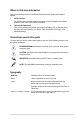
Where to find more information Refer to the following sources for additional information and for product and software updates. 1. 2. ASUS websites The ASUS website provides updated information on ASUS hardware and software products. Refer to the ASUS contact information. Optional documentation Your product package may include optional documentation, such as warranty flyers, that may have been added by your dealer. These documents are not part of the standard package.
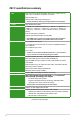
Z87-C specifications summary CPU LGA1150 socket for the 4th Generation Intel® Core™ i7/Intel® Core™i5/ Intel® Core™ i3, Pentium® and Celeron® processors Supports 22nm CPU Supports Intel® Turbo Boost Technology 2.0* Chipset Memory * The Intel® Turbo Boost Technology 2.0 support depends on the CPU types. Intel® Z87 Express Chipset 4 x DIMM, max. 32GB, DDR3 2800 (O.C.)* / 2666 (O.C.)* / 2600 (O.C.)* / 2500 (O.C.)* / 2400 (O.C.)* / 2200 (O.C.)* / 2133 (O.C.)* / 2000 (O.C.)* / 1866 (O.C.)* / 1800 (O.C.
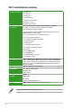
Z87-C specifications summary USB ASUS Unique features Intel® Z87 Express Chipset - supports ASUS USB 3.0 Boost Turbo Mode - 2 x USB 3.0/2.0 ports at mid-board for front panel support - 4 x USB 3.0/2.0 ports at rear panel (blue) - 8 x USB 2.0/1.
Z87-C specifications summary Rear Panel I/O Ports 1 x HDMI port 1 x D-Sub port 1 x DVI-D port 1 x LAN (RJ45) port 4 x USB 3.0/2.0 ports (blue) 2 x USB 2.0/1.1 ports 8-channel Audio I/O ports Internal I/O connectors 1 x 19-pin USB 3.0/2.0 connector supports additional 2 USB ports 3 x USB 2.0/1.1 connectors support additional 6 USB ports 6 x SATA 6.
Chapter 1 Product introduction Chapter 1: Product introduction Thank you for buying an ASUS® Z87-C motherboard! Before you start installing the motherboard, and hardware devices on it, check the items in your motherboard package. Refer to the specification list on page viii for the list of accessories. If any of the items is damaged or missing, contact your retailer. 1.
1.2 Motherboard overview Before you install the motherboard, study the configuration of your chassis to ensure that the motherboard fits into it. Ensure that you unplug the power cord before installing or removing the motherboard. Failure to do so can cause you physical injury and damage motherboard components. 1.2.1 Placement direction When installing the motherboard, ensure that you place it into the chassis in the correct orientation.
1.2.
1.2.4 Layout contents Connectors/Jumpers/Slots 1. ATX power connectors (24-pin EATXPWR, 8-pin EATX12V) 2. LGA1150 CPU socket 3. CPU, CPU optional, and chassis fan connectors (4-pin CPU_FAN, 4-pin CPU_OPT, 4-pin CHA_FAN1-3) 4. DDR3 DIMM slots 5. USB 3.0 connector (20-1 pin USB3_12) 6. Clear RTC RAM jumper 7. Intel® Z87 Serial ATA 6.0 Gb/s connectors (7-pin SATA6G_1-6 [yellow]) 8. DRCT (DirectKey) connector (2-pin DRCT) 9. System panel connector (20-8 pin PANEL) 10. USB 2.
1.3.1 • Ensure that you install the correct CPU designed for LGA1150 only. DO NOT install a CPU designed for LGA1155 and LGA1156 sockets on the LGA1150 socket. • Upon purchase of the motherboard, ensure that the PnP cap is on the socket and the socket contacts are not bent. Contact your retailer immediately if the PnP cap is missing, or if you see any damage to the PnP cap/socket contacts/motherboard components. ASUS will shoulder the cost of repair only if the damage is shipment/ transit-related.
1-6 ASUS Z87-C
1.3.
1.4 1.4.1 System memory Overview The motherboard comes with four Double Data Rate 3 (DDR3) Dual In-line Memory Modules (DIMM) slots. A DDR3 module is notched differently from a DDR or DDR2 module. DO NOT install a DDR or DDR2 memory module to the DDR3 slot. Recommended memory configurations Install one memory module in slot A2 first as a single-channel operation.
1.4.2 Memory configurations You may install 2GB, 4GB and 8GB unbuffered and non‑ECC DDR3 DIMMs into the DIMM sockets. • • You may install varying memory sizes in Channel A and Channel B. The system maps the total size of the lower-sized channel for the dual-channel configuration. Any excess memory from the higher-sized channel is then mapped for single-channel operation. According to Intel® CPU spec, DIMM voltage below 1.65V is recommended to protect the CPU.
Z87-C Motherboard Qualified Vendors Lists (QVL) DDR3 2800(O.C.) MHz capability Vendors Part No. Size SS/ DS Chip Brand Chip NO. Timing Voltage DIMM socket support (Optional) 1 2 4 G.SKILL F3-2800C11Q-16GTXD(XMP) 16GB (4x4GB) DS - - 11-13-13-35 1.65 • • • G.SKILL F3-2800C12Q-32GTXD(XMP) 32GB (4x8GB) DS - - 12-13-13-35 1.65 • • • G.SKILL F3-2800C12Q-32GTXDG(XMP) 32GB (4x8GB) DS - - 12-14-14-35 1.65 • • • APACER 78.BAGH5.AFD0C 8GB (2x4GB) DS - - 12-14-14-35 1.
DDR3 2400(O.C.) MHz capability Vendors Part No. Size SS/ DS Chip Brand Chip NO. Timing Voltage DIMM socket support (Optional) 1 2 4 A-DATA AX3U2400GC4G10(XMP) 4GB DS - - 10-12-12-31 1.65 • • • Apacer 78.BAGFL.AFD0C(XMP) 8GB (2x4GB) DS - - 11-12-12-30 - • • • Apacer 783BAGF3.AFD0C(XMP) 8GB (2x4GB) DS - - 11-11-11-30 - • • • CORSAIR CMGTX8(XMP) 8GB (4x2GB) SS - - 10-12-10-30 1.65 • • • CORSAIR CMZ16GX3M2A2400C10 (Ver4.
DDR3 2133(O.C.) MHz capability 1-12 Vendors Part No. Size SS/ DS Chip Brand Chip NO. Timing Voltage DIMM socket support (Optional) 1 2 4 A-DATA AX3U2133XC4G10(XMP) 4GB DS - - 10-11-11-30 1.65 • • • A-DATA AX3U2133XW8G10(XMP) 8GB DS - - 10-11-11-30 1.65 • • • Apacer 78.BAGE4.AFD0C(XMP) 8GB (2x4GB) DS - - 9-9-9-24 - • • • Apacer AHU04GFB33CAQ3R(XMP) 4GB DS - - 11-13-13-31 - • • • CORSAIR CMD8GX3M2A2133C9 (Ver1.
DDR3 2000(O.C.) MHz capability Vendors Part No. Size SS/ DS Chip Brand Chip NO. Timing Voltage DIMM socket support (Optional) 1 2 4 AEXEA AXA3ES2G2000LG28V(XMP) 2GB DS - - - 1.65 • • • AEXEA AXA3ES4GK2000LG28V(XMP) 4GB (2x2GB) DS - - - 1.65 • • • Apacer 78.AAGD5.9KD(XMP) 6GB (3x2GB) DS - - 9-9-9-27 - • • • Asint SLA302G08-ML2HB(XMP) 4GB DS Hynix H5TQ2G83BF RH9C 9-9-9-27 - • • • G.SKILL F3-16000CL9D-4GBRH(XMP) 4GB (2x2GB) DS - - 9-9-9-24 1.
DDR3 1866(O.C.) MHz capability Vendors Part No. Size SS/ DS Chip Brand Chip NO. Timing Voltage DIMM socket support (Optional) 1 2 CORSAIR CMZ8GX3M2A1866C9(XMP) 8GB (2x4GB) DS - - 9-10-9-27 1.5 • • CORSAIR CMZ8GX3M2A1866C9G (Ver5.12)(XMP) 8GB (2x4GB) DS - - 1866 9-10-9-27 1.5 • • • Crucial BLE4G3D1869DE1XT0.16F MD(XMP) 4GB DS - - 9-9-9-27 1.5 • • • G.SKILL F3-14900CL10Q264GBZLD(XMP) 64GB (8x8GB) DS - - 10-11-10-30 1.5 • • • G.
DDR3 1600 MHz capability Vendors Part No. Size SS/ DS Chip Brand Chip NO. Timing Voltage DIMM socket support (Optional) 1 2 4 Apacer 78.C1GET.9K10C 8GB DS Apacer AM5D6008 BQQSCK 11-1111-31 - • • • Apacer AHU04GFA60C9Q1D(XMP) 4GB DS - - 9-9-9-27 1.
DDR3 1600 MHz capability Vendors Part No. Size SS/ DS Chip Brand Chip NO.
DDR3 1600 MHz capability Vendors Part No. Size SS/ DS Chip Brand Chip NO. Timing Voltage 1 2 4 KINGSTON KHX16C10B1K2/ 16X(XMP) 16GB (2x8GB) DS - - - 1.5 • • • KINGSTON KHX16C9K2/16 16GB (2x8GB) DS - - 1333-99-9-24 1.5 • • KINGSTON KHX16C9P1K2/16 16GB (2x8GB) DS - - - 1.5 • • • KINGSTON KVR16N11/4 4G DS Hynix H5TQ2G83CFRPBC - 1.5 • • • KINGTIGER KTG2G1600PG3(XMP) 2GB DS - - - - • • • MICRON MT16JTF1G64AZ1G6D1 8GB DS MICRON D9PBC - 1.
DDR3 1333 MHz capability Vendors Part No. Size SS/ DS Chip Brand Chip NO.
DDR3 1333 MHz capability Vendors Part No. Size SS/ DS Chip Brand Chip NO. Timing Voltage DIMM socket support (Optional) 1 2 4 G.SKILL F3-10666CL9D8GBRL 8GB (2x4GB) DS - - 9-9-9-24 1.5 • • • G.SKILL F3-10666CL9D8GBXL 8GB (2x4GB) DS - - 9-9-9-24 1.5 • • • GEIL GB34GB1333C7DC 4GB (2x2GB) DS GEIL GL1L128M8 8BA15FW 7-7-7-24 1.5 • • • GEIL GET316GB1333 C9QC 16GB (4x4GB) DS - - 9-9-9-24 1.
DDR3 1333 MHz capability 1-20 Vendors Part No. Size SS/ DS Chip Brand Chip NO. Timing Voltage DIMM socket support (Optional) 1 2 OCZ OCZ3G1333L V4GK 4GB (2x2GB) DS - - 9-9-9 1.65 • • OCZ OCZ3G1333L V8GK 8GB (2x4GB) DS - - 9-9-9 1.65 • • 4 OCZ OCZ3G1333L V8GK 8GB (2x4GB) DS - - 9-9-9 1.65 • • OCZ OCZ3RPR1333 C9LV8GK 8GB (2x4GB) DS - - 9-9-9 1.65 • • Patriot PG38G1333EL (XMP) 8GB DS - - - 1.
Side(s): SS - Single-sided DS - Double-sided DIMM support: (1) Supports one (1) module inserted into any slot as Single-channel memory configuration. We suggest that you install the module into A2 slot. (2) Supports two (2) modules inserted into either the yellow slots or the dark brown slots as one pair of Dual-channel memory configuration. We suggest that you install the modules into slots A2 and B2 for better compatibility.
To remove a DIMM 1-22 ASUS Z87-C
1.5 Expansion slots Unplug the power cord before adding or removing expansion cards. Failure to do so may cause you physical injury and damage motherboard components. Slot No. Expansion Slots PCIe 2.0 x1_1 slot PCIe 3.0 x16_1 slot PCI_1 slot PCI_2 slot PCIe 2.0 x16_2 slot PCI_3 slot PCIe 2.0 x1_2 slot IRQ assignments for this motherboard SATA controller 0 SATA controller 1 SMBUS Controller Thermal Controller USB 2.0 Controller 0 USB 2.
1.5.1 Installing an expansion card To install an expansion card: 1. Before installing the expansion card, read the documentation that came with it and make the necessary hardware settings for the card. 2. Remove the system unit cover (if your motherboard is already installed in a chassis). 3. Remove the bracket opposite the slot that you intend to use. Keep the screw for later use. 4. Align the card connector with the slot and press firmly until the card is completely seated on the slot. 5.
1.6 Onboard buttons Onboard switches allow you to fine-tune performance when working on a bare or opencase system. This is ideal for overclockers and gamers who continually change settings to enhance system performance. DirectKey button This feature allows your system to go to the BIOS Setup program with the press of a button. With DirectKey, you can enter the BIOS anytime without having to press the key during POST.
1.7 1. 2. 1-26 Onboard LEDs Standby power LED (SB_PWR) The motherboard comes with a standby power LED that lights up to indicate that the system is ON, in sleep mode, or in soft-off mode. This is a reminder that you should shut down the system and unplug the power cable before removing or plugging in any motherboard component. The illustration below shows the location of the onboard LED.
1.8 Jumpers Clear RTC RAM jumper (3-pin CLRTC) This jumper allows you to clear the Real Time Clock (RTC) RAM in CMOS. You can clear the CMOS memory of date, time, and system setup parameters by erasing the CMOS RTC RAM data. The onboard button cell battery powers the RAM data in CMOS, which include system setup information such as system passwords. To erase the RTC RAM: 1. Turn OFF the computer and unplug the power cord. 2. Move the jumper cap from pins 1-2 (default) to pins 2-3.
1.9 1.9.1 Connectors Rear panel connectors Rear panel connectors 1. PS/2 keyboard/mouse combo port 6. HDMI port 2. VGA port 7. DVI-D port 3. USB 3.0 ports 5 and 6 8. USB 3.0 ports 3 and 4 4. Intel® LAN (RJ-45) port* 9. Audio I/O ports** 5. USB 2.0 ports 7 and 8 * and **: Refer to the tables for LAN port LEDs and audio port definitions.
** Audio 2, 4, 6, or 8-channel configuration Port Light Blue Lime Pink Orange Black Gray 1. 2. Headset 2-channel Line In Line Out Mic In – – – 4-channel 6-channel 8-channel Line In Front Speaker Out Mic In – Rear Speaker Out – Line In Front Speaker Out Mic In Center/Subwoofer Rear Speaker Out – Line In Front Speaker Out Mic In Center/Subwoofer Rear Speaker Out Side Speaker Out Line In port (light blue). This port connects to the tape, CD, DVD player, or other audio sources. Line Out port (lime).
2. 1-30 ATX power connectors (24-pin EATXPWR; 8-pin EATX12V) These connectors are for ATX power supply plugs. The power supply plugs are designed to fit these connectors in only one orientation. Find the proper orientation and push down firmly until the connectors completely fit. • For a fully configured system, we recommend that you use a power supply unit (PSU) that complies with ATX 12 V Specification 2.0 (or later version) and provides a minimum power of 350 W.
3. Intel® Z87 Serial ATA 6.0 Gb/s connectors (7-pin SATA6G_1-6 [yellow]) These connectors connect to Serial ATA 6.0 Gb/s hard disk drives via Serial ATA 6.0 Gb/s signal cables. If you installed Serial ATA hard disk drives, you can create a RAID 0, 1, 5, and 10 configuration with the Intel® Rapid Storage Technology through the onboard Intel® Z87 chipset. 4.
5. CPU, CPU optional, and chassis fan connectors (4-pin CPU_FAN; 4-pin CPU_OPT; 4-pin CHA_FAN1-3) Connect the fan cables to the fan connectors on the motherboard, ensuring that the black wire of each cable matches the ground pin of the connector. Do not forget to connect the fan cables to the fan connectors. Insufficient air flow inside the system may damage the motherboard components.
6. Serial port connector (10-1 pin COM) The connector is for a serial (COM) port. Connect the serial port module cable to the connector, then install the module to a slot opening at the back of the system chassis. The serial port bracket (COM) is purchased separately. 7. USB 3.0 connector (20-1 pin USB3_12) This connector allows you to connect a USB 3.0 module for additional USB 3.0 front or rear panel ports. With an installed USB 3.0 module, you can enjoy all the benefits of USB 3.
8. USB 2.0 connectors (10-1 pin USB910; USB1112; USB1314) These connectors are for USB 2.0 ports. Connect the USB module cable to any of these connectors, then install the module to a slot opening at the back of the system chassis. These USB connectors comply with USB 2.0 specification that supports up to 480 Mbps connection speed. Never connect a 1394 cable to the USB connectors.
9. 10. Front panel audio connector (10-1 pin AAFP) This connector is for a chassis-mounted front panel audio I/O module that supports either HD Audio or legacy AC`97 audio standard. Connect one end of the front panel audio I/O module cable to this connector. • We recommend that you connect a high-definition front panel audio module to this connector to avail of the motherboard’s high-definition audio capability.
11. • • • • • 1-36 System panel connector (20-8 pin PANEL) This connector supports several chassis-mounted functions. System power LED (2-pin PLED) This 2-pin connector is for the system power LED. Connect the chassis power LED cable to this connector. The system power LED lights up when you turn on the system power, and blinks when the system is in sleep mode. Hard disk drive activity LED (2-pin IDE_LED) This 2-pin connector is for the HDD Activity LED.
1.10 1.10.1 1.10.2 Software support Installing an operating system • This motherboard supports Windows® 8 32/64-bit and Windows® 7 32/64-bit operating systems (OS). • Motherboard settings and hardware options vary. Use the setup procedures presented in this chapter for reference only. Refer to your OS documentation for detailed information.
1-38 ASUS Z87-C
Chapter 2: BIOS information Chapter 2 BIOS information 2.1 Managing and updating your BIOS The ASUS website publishes the latest BIOS versions to provide enhancements on system stability, compatibility, or performance. However, BIOS updating is potentially risky. If there is no problem using the current version of BIOS, DO NOT manually update the BIOS. Inappropriate BIOS updating may result in the system’s failure to boot.
2.1.2 ASUS EZ Flash 2 The ASUS EZ Flash 2 feature allows you to update the BIOS without using an OS‑based utility or a bootable floppy disk. Before you start using this utility, download the latest BIOS file from the ASUS website at www.asus.com. 2-2 1. Insert the USB flash disk that contains the latest BIOS file to the USB port. 2. Enter the Advanced Mode of the BIOS setup program. Go to the Tool menu to select ASUS EZ Flash 2 Utility and press to enable it. 3.
2.1.3 ASUS CrashFree BIOS 3 utility The ASUS CrashFree BIOS 3 is an auto recovery tool that allows you to restore the BIOS file when it fails or gets corrupted during the updating process. You can restore a corrupted BIOS file using the motherboard support DVD or a USB flash drive that contains the updated BIOS file. • Before using this utility, rename the BIOS file in the removable device into Z87C.CAP.
2.1.4 ASUS BIOS Updater The ASUS BIOS Updater allows you to update BIOS in DOS environment. This utility also allows you to copy the current BIOS file that you can use as a backup when the BIOS fails or gets corrupted during the updating process. The succeeding utility screens are for reference only. The actual utility screen displays may not be same as shown. Before updating BIOS 1. Prepare the motherboard support DVD and a USB flash drive in FAT32/16 format and single partition. 2.
Updating the BIOS file To update the BIOS file using BIOS Updater 1. At the FreeDOS prompt, type bupdater /pc /g and press . D:\>bupdater /pc /g 2. The BIOS Updater screen appears as below. ASUSTek BIOS Updater for DOS V1.30 [2013/02/22] FLASH TYPE: MX1C 25L1065A Current ROM Update ROM BOARD:Z87-C BOARD: UNKNOWN VER: 0204 VER: UNKNOWN DATE: 01/01/2013 DATE: UNKNOWN PATH: A:\ Z87C.CAP A: Note [Enter] Select or Load [Up/Down/Home/End] Move 3.
2.2 BIOS setup program Use the BIOS Setup to update the BIOS or configure its parameters. The BIOS screen include navigation keys and brief onscreen help to guide you in using the BIOS Setup program. Entering BIOS at startup To enter BIOS Setup at startup: • Press during the Power-On Self Test (POST). If you do not press , POST continues with its routines. Entering BIOS Setup after POST To enter BIOS Setup after POST: • Press ++ simultaneously.
2.2.1 EZ Mode By default, the EZ Mode screen appears when you enter the BIOS setup program. The EZ Mode provides you an overview of the basic system information, and allows you to select the display language, system performance mode and boot device priority. To access the Advanced Mode, click Exit/Advanced Mode, then select Advanced Mode or press F7 hot key for the advanced BIOS settings. The default screen for entering the BIOS setup program can be changed. Refer to the Setup Mode item in section 2.
2.2.2 Advanced Mode The Advanced Mode provides advanced options for experienced end-users to configure the BIOS settings. The figure below shows an example of the Advanced Mode. Refer to the following sections for the detailed configurations. To access the Advanced Mode, click Exit, then select Advanced Mode or press F7 hotkey.
Menu items The highlighted item on the menu bar displays the specific items for that menu. For example, selecting Main shows the Main menu items. The other items (Ai Tweaker, Advanced, Monitor, Boot, Tool, and Exit) on the menu bar have their respective menu items. Back button This button appears when entering a submenu. Press or use the USB mouse to click this button to return to the previous menu screen.
Last Modified button This button shows the items that you last modified and saved in BIOS Setup. 2.3 My Favorites MyFavorites is your personal space where you can easily save and access your favorite BIOS items. Adding items to My Favorites To add frequently-used BIOS items to My Favorites: 1. Use the arrow keys to select an item that you want to add. When using a mouse, hover the pointer to the item. 2. Press on your keyboard or right-click on your mouse to add the item to My Favorites page.
2.4 Main menu 2.4.1 System Language [English] The Main menu screen appears when you enter the Advanced Mode of the BIOS Setup program. The Main menu provides you an overview of the basic system information, and allows you to set the system date, time, language, and security settings. Allows you to choose the BIOS language version from the options. Configuration options: [English] [Français] [Español] [Deutsch] [Pyccкий] [日本語] [繁體中 文][簡體中文] 2.4.2 System Date 2.4.3 System Time 2.4.
Administrator Password If you have set an administrator password, we recommend that you enter the administrator password for accessing the system. Otherwise, you might be able to see or change only selected fields in the BIOS setup program. To set an administrator password: 1. Select the Administrator Password item and press . 2. From the Create New Password box, key in a password, then press . 3. Confirm the password when prompted. To change an administrator password: 1.
2.5 Ai Tweaker menu The Ai Tweaker menu items allow you to configure overclocking-related items. Be cautious when changing the settings of the Ai Tweaker menu items. Incorrect field values can cause the system to malfunction. The configuration options for this section vary depending on the CPU and DIMM model you installed on the motherboard. Scroll down to display other BIOS items.
2.5.1 Ai Overclock Tuner [Auto] Allows you to select the CPU overclocking options to achieve the desired CPU internal frequency. Select any of these preset overclocking configuration options: [Auto] Loads the optimal settings for the system. [X.M.P.] If you install memory modules supporting the eXtreme Memory Profile (X.M.P.) Technology, choose this item to set the profiles supported by your memory modules for optimizing the system performance.
2.5.3 CPU Core Ratio [Sync All Cores] Allows you to set the CPU ratio and synchronize automatically either per core or all cores. Configuration options: [Auto] [Sync All Cores] [Per Core] When the CPU Core Ratio is set to [Per Core], the following item appears: 1-Core Ratio Limit [Auto] Select [Auto] to apply the CPU default Turbo Ratio setting or manually assign a 1-Core Limit value that must be higher than or equal to the 2-Core Ratio Limit.
2.5.7 CPU bus speed : DRAM speed ratio mode [Auto] Allows you to set the CPU bus speed to DRAM speed ratio mode. [Auto] DRAM speed is set to the optimized settings. [100:100] The CPU bus speed to DRAM speed ratio is set to 100:100. [100:133] The CPU bus speed to DRAM speed ratio is set to 100:133. 2.5.8 Memory Frequency [Auto] 2.5.9 CPU Graphics Max. Ratio [Auto] Allows you to set the memory operating frequency. The configuration options vary with the BCLK/PCIE Frequency item settings.
DO NOT remove the thermal module. The thermal conditions should be monitored. CPU Voltage Frequency [Auto] Frequency switching affects the VRM transient response and the thermal component conditions. Higher frequency gets quicker transient response. Configuration options: [Auto] [Manual] DO NOT remove the thermal module when setting this item to [Manual Mode]. The thermal conditions should be monitored. The following item appears only when you set the CPU Voltage Frequency to [Manual].
Choose a higher value when overclocking, or under a high CPU loading for extra power support. CPU Power Thermal Control [124] A higher temperature brings a wider CPU power thermal range and extends the overclocking tolerance to enlarge the O.C. potential. Use the <+> or <-> keys to adjust the value. The values depend on the CPU installed. DO NOT remove the thermal module. The thermal conditions should be monitored. 2.5.
CPU Internal Power Switching Frequency Frequency Tuning Mode [Auto] Allows you to increase or decrease the switching frequency of the internal regulator. Decrease to help consume less power or increase to help votlage stability. When this item is set to [+] or [-], the Frequency Tuning Offset appears and allows you to set its value from 0% to 6%.
Power Current Offset [Auto] Allows you to increase or decrease the output current sensed by the CPU. It finds the balance between optimal regulating while staying below the current threshold. Configuration options: [Auto] [100%] [87.5%] [75.0%] [62.5%] [50.0%] [37.5%] [25.0%] [12.5%] [0%] [-12.5%] [-25.0%] [-37.5%] [-50.0%] [-62.5%] [-75.0%] [-87.5%] [-100%] Power Fast Ramp Response [Auto] Allows you to increase to enhance the response of the voltage regulator during the load transient.
Offset Mode Sign [+] [+] To offset the voltage by a positive value. [–] To offset the voltage by a negative value. CPU Core Voltage Offset Use the <+> or <-> keys to adjust the value. The values range from 0.001V to 0.999V with a 0.001V interval. 2.5.17 CPU Cache Voltage [Auto] Allows you to configure the amount of voltage fed to the uncore of the processor including its cache. Increase the voltage when increasing Ring frequency.
CPU Graphics Voltage Override [Auto] Allows you to set the CPU Graphics Voltage override. By default, this item takes the standard value of the installed CPU. You can use the <+> or <-> keys to adjust the value. The values range from 0.001V to 1.920V with a 0.001V interval. The following items appear only when you set the CPU Core Voltage to [Offset Mode]. Offset Mode Sign [+] [+] To offset the voltage by a positive value. [–] To offset the voltage by a negative value.
CPU Analog I/O Voltage Offset [Auto] Allows you to configure the amount of voltage fed to the analog portion of the I/O on the processor. By default, this item takes the standard value of the installed CPU. Increase the amount of voltage when increasing DRAM frequency. You can use the <+> or <-> keys to adjust the value. The values range from 0.001V to 0.999V with a 0.001V interval. 2.5.21 CPU Digital I/O Voltage Offset Mode Sign [+] [+] To offset the voltage by a positive value.
2.5.24 PCH VLX Voltage [Auto] 2.5.25 PCH Voltage [Auto] Allows you to set the I/O voltage on the PCH (Platform Controller Hub). You can use the <+> or <-> keys to adjust the value. The values range from 1.2000V to 2.0000V with a 0.0125V interval. Allows you to set the Core voltage for the PCH (Platform Controller Hub). You can use the <+> or <-> keys to adjust the value. The values range from 0.80V to 1.70V with a 0.01V interval.
2.6 Advanced menu The Advanced menu items allow you to change the settings for the CPU and other system devices. Be cautious when changing the settings of the Advanced menu items. Incorrect field values can cause the system to malfunction. 2.6.1 CPU Configuration The items in this menu show the CPU-related information that the BIOS automatically detects. The items shown in submenu may be different due to the CPU you installed.
Active Processor Cores [All] Allows you to choose the number of CPU cores to activate in each processor package. Configuration options: [All] [1] [2] [3] Limit CPUID Maximum [Disabled] When set to [Enabled], this item allows the legacy OS to boot even without support for CPUs with extended CPUID functions.
Turbo Mode [Enabled] Allows you to automatically set the processor cores to run faster than the base frequency when operating below power, current and temperature specification limit. Configuration options: [Enabled] [Disabled] CPU C States Allows you to enable or disable the CPU C states. Configuration options: [Auto] [Enabled] [Disabled] The following items appear only when you set the CPU C States to [Enabled].
PCIe Speed [Auto] Allows you to select the PCI Express port speed. Configuration options: [Auto] [Gen1] [Gen2] Intel(R) Rapid Start Technology [Disabled] Allows your computer to quickly resume from slow-power hibernate state in seconds. Saving your system memory to the designated SSD, it provides your computer a faster wake-up response time, while still keeping the energy use low.
SATA Mode Selection [AHCI] Allows you to set the SATA configuration. [Disabled] Disables the SATA function. [IDE] Set to [IDE Mode] when you want to use the Serial ATA hard disk drives as Parallel ATA physical storage devices. [AHCI] Set to [AHCI Mode] when you want the SATA hard disk drives to use the AHCI (Advanced Host Controller Interface).
DVI Port Audio Allows you to enable or disable the DVI audio port. Configuration options: [Disable] [Enable] Graphics Configuration Allows you to select a primary display from iGPU, and PCIe graphical devices. Primary Display [Auto] Allows you to select the primary display from iGPU, PCIE and PCI Graphics devices. Configuration options: [Auto] [iGPU] [PCIE] [PCI] iGPU Memory [Auto] Allows you to select the amount of system memory allocated to DVMT 5.0 by the iGPU.
Memory Configuration Allows you to configure the memory configuration parameters. Memory Scrambler [Enabled] Allows you to enable or disable the Memory Scrambler support. Configuration options: [Enabled] [Disabled] Memory Remap [Enabled] Allows you to enable remapping the memory above 4GB. Configuration options: [Enabled] [Disabled] 2.6.5 USB Configuration The items in this menu allow you to change the USB-related features. The USB Devices item shows the auto-detected values.
2.6.6 Platform Misc Configuration The items in this menu allow you to configure the platform-related features. PCI Express Native Power Management [Disabled] Allows you to enhance the power saving feature of PCI Express and perform ASPM operations in the operating system. Configuration options: [Disabled] [Enabled] The following item appears only when you set the PCI Express Native Power Management to [Enabled]. Native ASPM [Disabled] [Enabled] [Disabled] 2.6.
Realtek LAN Controller [Enabled] [Enabled] [Disabled] Enables the Realtek® LAN controller. Disables the Realtek® LAN controller. The following item appears only when you set the Realtek LAN Controller to [Enabled]. Realtek PXE OPROM [Disabled] Allows you to enable or disable the PXE OptionRom of the Realtek LAN controller. Configuration options: [Enabled] [Disabled] Serial Port Configuration Allows you to set the parameters of the serial ports.
Power On By PCIE/PCI [Disabled] [Disabled] [Enabled] Disables the PCIE/PCI devices to generate a wake-on-LAN feature of the Intel®/Realtek LAN device or other installed PCIE LAN devices. Enables the PCIE/PCI devices to generate a wake-on-LAN feature of the Intel®/Realtek LAN device or other installed PCIE LAN devices. Power On By Ring [Disabled] Allows you to enable or disable the Wake-on-Modem function Configuration options: [Disabled] [Enabled] Power On By RTC [Disabled] [Disabled] [Enabled] 2.6.
2.7 Monitor menu 2.7.1 CPU Temperature / MB Temperature [xxxºC/xxxºF] 2.7.2 CPU Fan Speed [xxxx RPM] or [Ignore] / [N/A], CPU OPT Speed [xxxx RPM] or [Ignore] / [N/A], Chassis Fan 1/3 Speed [xxxx RPM] or [Ignore] / [N/A] The Monitor menu displays the system temperature/power status, and allows you to change the fan settings. The onboard hardware monitor automatically detects and displays the CPU and motherboard temperatures. Select [Ignore] if you do not wish to display the detected temperatures.
2.7.4 CPU Q-Fan Control [Enabled] Allows you to set the CPU Q-Fan operating mode. Configuration options: [Disabled] [Enabled] The following items appear only when you set the CPU Q-Fan Control to [Enabled]. CPU Fan Speed Low Limit [600 RPM] Allows you to set the low limit warning for CPU Fan speed. Configuration options: [Ignore] [200 RPM] [300 RPM] [400 RPM] [500 RPM] [600 RPM] CPU Fan Profile [Standard] Allows you to set the appropriate performance level of the CPU fan.
Chassis Fan Speed Low Limit 1/3 [600 RPM] This item appears only when you enable the Chassis Q-Fan Control feature and allows you to disable or set the chassis fan warning speed. Configuration options: [Ignore] [200 RPM] [300 RPM] [400 RPM] [500 RPM] [600 RPM] Chassis Fan 1/3 Profile [Standard] This item appears only when you enable the Chassis Q-Fan Control feature. It allows you to set the appropriate performance level of the chassis fan.
2.8 Boot menu The Boot menu items allow you to change the system boot options. Boot Configuration 2.8.1 [Disabled] Fast Boot [Disabled] Allows your system to go back to its normal boot speed. [Enabled] Allows your system to accelerate the boot speed. The following items appear only when you set the Fast Boot to [Enabled]. USB Support [Partial In...] 2-38 [Disabled] All USB devices will not be available until OS boot up for a fastest POST time.
PS/2 Keyboard and Mouse Support [Auto] Select any of these settings when PS/2 keyboard and mouse are installed. These settings only apply when Fast Boot is enabled. [Auto] For a faster POST time, PS/2 devices will only be available when the system boots up or rebooted when the PS/2 devices have not been reconnected or changed. If you disconnect or change PS/2 devices before restarting the system, PS/2 devices will not be available and BIOS setup program will not be accessible via PS/2 devices.
Post Delay Time [3 sec] This item allows you to select a desired additional POST waiting time to easily enter the BIOS Setup. You can only execute the POST delay time during normal boot. The values range from 0 to 10 seconds. This feature will only work when set under normal boot. The following items appear only when you set the Boot Logo Display to [Disabled].
Launch CSM [Auto] [Auto] The system automatically detects the bootable devices and the add-on devices. [Enabled] For better compatibility, enable the CSM to fully support the non-UEFI driver add-on devices or the Windows® UEFI mode. [Disabled] Disable the CSM to fully support the non-UEFI driver add-on devices or the Windows® UEFI mode. The following items appear only when you set the Launch CSM to [Enabled].
The following item appears only when you set the OS Type to [Windows UEFI mode]. Key Management This item appears only when you set OS Type to [Windows UEFI Mode]. It allows you to manage the Secure Boot keys. Install Default Secure Boot keys Allows you to immediately load the default Security Boot keys, Platform key (PK), Key-exchange Key (KEK), Signature database (db), and Revoked Signatures (dbx). When the default Secure boot keys are loaded, the PK state will change from Unloaded mode to loaded mode.
DB Management The db (Authorized Signature database) lists the signers or images of UEFI applications, operating system loaders, and UEFI drivers that you can load on the single computer. Delete the db Allows you to delete the db file from your system. Configuration options: [Yes] [No] Load db from File Allows you to load the downloaded db from a USB storage device. Append db from File Allows you to load the additional db from a storage device so that more images can be loaded securely.
2.8.13 Boot Override 2.9 Tools menu 2.9.1 ASUS EZ Flash 2 Utility These items displays the available devices. The number of device items that appears on the screen depends on the number of devices installed in the system. Click an item to start booting from the selected device. The Tools menu items allow you to configure options for special functions. Select an item then press to display the submenu. Allows you to run ASUS EZ Flash 2. When you press , a confirmation message appears.
Load from Profile Allows you to load the previous BIOS settings saved in the BIOS Flash. Key in the profile number that saved your BIOS settings, press , and then select Yes. 2.9.3 • DO NOT shut down or reset the system while updating the BIOS to prevent the system boot failure! • We recommend that you update the BIOS file only coming from the same memory/ CPU configuration and BIOS version. ASUS SPD Information Allows you to view the DRAM SPD information.
2.10 Exit menu 2.10.1 Load Optimized Defaults 2.10.2 Save Changes & Reset 2.10.3 Discard Changes & Exit 2.10.4 ASUS EZ Mode 2.10.5 Launch EFI Shell from filesystem device The Exit menu items allow you to load the optimal default values for the BIOS items, and save or discard your changes to the BIOS items. You can access the EZ Mode from the Exit menu. This option allows you to load the default values for each of the parameters on the Setup menus.
Appendices Appendices Notices Federal Communications Commission Statement This device complies with Part 15 of the FCC Rules. Operation is subject to the following two conditions: • • This device may not cause harmful interference. This device must accept any interference received including interference that may cause undesired operation. This equipment has been tested and found to comply with the limits for a Class B digital device, pursuant to Part 15 of the FCC Rules.
Canadian Department of Communications Statement This digital apparatus does not exceed the Class B limits for radio noise emissions from digital apparatus set out in the Radio Interference Regulations of the Canadian Department of Communications. This class B digital apparatus complies with Canadian ICES-003.
ASUS contact information ASUSTeK COMPUTER INC. Address Telephone Fax E-mail Web site Technical Support Telephone Online support 15 Li-Te Road, Peitou, Taipei, Taiwan 11259 +886-2-2894-3447 +886-2-2890-7798 info@asus.com.tw www.asus.com.tw +86-21-38429911 support.asus.
(510)739-3777/(510)608-4555 800 Corporate Way, Fremont, CA 94539. Asus Computer International Signature : Date : Representative Person’s Name : Apr. 01, 2013 Steve Chang / President This device complies with part 15 of the FCC Rules. Operation is subject to the following two conditions: (1) This device may not cause harmful interference, and (2) this device must accept any interference received, including interference that may cause undesired operation.