PL-X31M, PL-X32M HomePLUG AV Ethernet adapter User Manual
PL-X31M,PL-X32M User Manual Contents 1 Introduction...................................................................................................... 1 1.1 System Requirements ......................................................................... 1 1.2 Packing List......................................................................................... 1 2 Safety Precautions .......................................................................................... 2 3 Adapter.......................
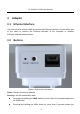
PL-X31M,PL-X32M User Manual 1 Introduction The PL-X31M, PL-X32M (also called “the device” hereinafter) is a low power consumption PLC device developed based on the master chip of INT6400. It can transmit the network data in the power line. The device is compatible with the latest requirements of the EUP Directive. When the device enters the lower power consumption mode, the consumption is less than 1W.
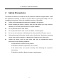
PL-X31M,PL-X32M User Manual 2 Safety Precautions This device is used for to connect to the AC power line. Before using the device, read the instructions carefully, in order to use the device correctly and safely. For the installation instructions, refer to the installation section of this guide. Follow all the warnings and instructions marked on the product. Before cleaning the device, unplug it from the wall outlet. Use a dry cloth for cleaning. Do not use liquid cleaners or aerosol cleaners.
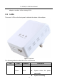
PL-X31M,PL-X32M User Manual 3 3.1 Adapter Ethernet Interface Use one end of a network cable to connect the Ethernet interface. Use the other end of the cable to connect the Ethernet interface of the computer or another Ethernet-enabled network device. 3.2 Buttons Figure 1 Side panel of the device Reset: Restore the factory defaults. Security: Set the membership state. Pressing and holding the NMK button for more than 10 seconds randomizes the NMK value.
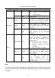
PL-X31M,PL-X32M User Manual adapter a member of the existing AVLN. 3.3 LEDs There are 3 LEDs on the front panel to indicate the status of the adapter. Figure 2 Top view The following table describes the LEDs on the device. LED Power Color Behavior Green On Green Blink Description Power is on System enters the power save mode. 4 System is resetting.
PL-X31M,PL-X32M User Manual LED Color Behavior Description System is in the process of security setup. Ethernet - Off Power is off. Green On The device is connecting to other devices via the Ethernet interface but not communicating with them. Green Blink The device is receiving or transmitting data via the Ethernet interface. - Off The device is not connecting to other devices via the Ethernet interface. Green/Red On The device has connected to the power line network.
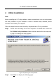
PL-X31M,PL-X32M User Manual 4 Utility Installation Note: Before installing the PLC utility software, make sure that there is no any other power line utility installed on your computer. If there is another utility installed, please uninstall it and restart your computer. Follow the steps below to install the utility. No password or CD-Key is needed. Step1 Please insert the utility CD into the computer’s CD-ROM drive. Select the PLC 200AV Utility Installation folder and then double-click the setup.exe.
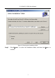
PL-X31M,PL-X32M User Manual Figure 4 Selecting the installation folder Step3 Click Browse… to select the installation folder, and then click Next > to continue.
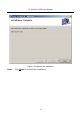
PL-X31M,PL-X32M User Manual Figure 5 Completing the installation Step4 Click Close to complete the installation.
PL-X31M,PL-X32M User Manual 5 5.1 How to Use the Utility Main Tab The Main screen provides a list of all power line devices logically connected to the computer when the utility is running. The top panel shows local HomePlug devices connected to the network interface card (NIC) of the computer. Click Connect. The utility automatically scans the power line periodically for other HomePlug devices when it is connected to the local device.
PL-X31M,PL-X32M User Manual whether the autoscan function is on. The following information is displayed for all devices that appear in the lower panel. Device Name This column shows the default device name, which may be modified. To change the name, click Rename or click the name and edit it in the list. MAC Address This column shows the MAC addresses of the remote devices. Password By default, this column is blank. You can click Enter Password to change it.
PL-X31M,PL-X32M User Manual Figure 7 Setting a device password Step3 Click OK to verify the password. The password field accepts the device password in any case formats, with or without dash. A confirmation box appears if the password is entered correctly. If a device is not found, a message appears, providing suggestions to solve the common problems. This process takes a few seconds. Add This button is used to add a remote device to the existing network by entering the device password of the device.
PL-X31M,PL-X32M User Manual Figure 8 Adding a remote device Note: The device must be in the power line (plugged in), so that you can confirm the password and add the device to the network. If the device is not located, a warning message appears. Scan This button is used to perform an immediate search for HomePlug devices connected to the Power line network. By default, the utility automatically scans every a few seconds and updates the displayed information. 5.
PL-X31M,PL-X32M User Manual All HomePlug devices are loaded using a default logical network (network name), which is normally “HomePlug”. In the Privacy screen, you can modify a private network by changing network names and passwords of devices. Click Use Default or enter HomePlug as the network name, to reset to the HomePlug network (Public). Figure 9 Privacy tab Note: If the network name changes to anything other than HomePlug, the network type in the main screen is displayed as Private.
PL-X31M,PL-X32M User Manual network name) appears in the device list. Set All Devices This button is used to change the logical network of all devices that appear in the main panel. If these devices whose passwords have been entered for the same logical network, a dialog box appears, indicating successful operation. For devices whose passwords are not entered, a dialog box appears indicating operation failure. 5.
PL-X31M,PL-X32M User Manual Figure 10 Diagnostics tab The Lower panel displays the history of all remote devices appeared on the computer over a certain period of time. All the devices and the parameters of the devices on the power line network are listed. Devices that are active on the current logical network show a transfer rate in the rate column. Devices on other networks, or devices that no longer exist are shown with a “?” in the rate column.
PL-X31M,PL-X32M User Manual printed for reference for a technical support call. Click delete to delete the devices which are no longer part of the network. A dialog window pops up with a confirmation message if the user wants to delete a device whose password has been entered. 5.4 About Tab The About screen shows the software version and provides a html link to a website, such as www.PowerPacket.com. Clicking the web address, it enters into the web site.
PL-X31M,PL-X32M User Manual 6 How to Use the NMK Pushbutton This section describes how to add new devices or remove old devices from a HomePlug AV logical network (AVLN) by using a NMK pushbutton. Power LED status indicates the operation progress and result. 6.1 Forming a HomePlug AV Logical Network When two devices with different NMK values are connected to the same power line, and the user wants them to form a logical network. Step1 Press the NMK button on device A for less than 3 seconds.
PL-X31M,PL-X32M User Manual 6.2 Joining a Network In this scenario a network exists, a new device, the ‘joiner’, wants to join the network. Any device on the existing network can become the ‘adder’. Step1 Press the pushbutton on the ‘joiner’ for at least 3 seconds. Step2 Press the pushbutton on any network device for less than 3 seconds, making it the ‘adder’. Please press this pushbutton within 1 minute. Step3 Wait for the connection to complete.
PL-X31M,PL-X32M User Manual Step2 Wait for the reset to complete. The Power LED on the ‘leaver’ momentarily extinguishes during reset, blinks during restart, then illuminates steadily. No error occurs. The user can disconnect the device from the medium or join it to another logical network on the same medium when it is completed. A PLC B PLC C PLC A, B and C form an AVLN A wants to leave the AVLN Press NMK button on A more than 10 sec.
PL-X31M,PL-X32M User Manual Appendix A Specifications Chipset Intellon INT6400 Protocol Compliant with HomePlug AV 1.1 Co-existing with existing HomePlug 1.
PL-X31M,PL-X32M User Manual Certifications CE, UL, FCC Part 15 Class B Green Standard RoHS Physical Characteristics L×W×H: 90 mm × 55 mm × 34 mm Weight 108 g 21
PL-X31M,PL-X32M User Manual Appendix B Acronyms and Abbreviations AVLN AV In-home Logical Network, the AVLAN is the set of STAs that possess the same network Membership key, every AVLN is managed by a single CCo CCo Central Coordinator, the CCo is a superset of a STA which includes terminal equipment identifiers and global link identifiers CSMA/CA Carrier Sense Avoidance DAK Device Access Key DM Device Manager IGMP Internet Group Management Protocol NEK Network Encryption Key NID Network I
PL-X31M,PL-X32M User Manual Appendix C About QoS PLC 200AV allows 4 levels of Channel Access Priority (CAP (0 – 3)). The 8 levels of VLAN Ethernet tags must be mapped to the 4 levels of CAP priority, where CAP 3 is the highest priority and CAP 0 is the lowest. CAP 3 priority is used for voice and network management frames. CAP 2 is used for streaming video and music while CAP 1 and CAP 0 are used for data.
PL-X31M,PL-X32M User Manual Federal Communication Commission Interference Statement This equipment has been tested and found to comply with the limits for a Class B digital device, pursuant to Part 15 of the FCC Rules. These limits are designed to provide reasonable protection against harmful interference in a residential installation.