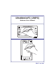
UltraMobilePC (UMPC) Hardware User’s Manual 1.3M PIXELS 1.
UltraMobilePC Table of Contents Table of Contents 1. Introducing the UltraMobilePC About This User’s Manual .......................................................................... 6 Notes For This Manual........................................................................... 6 Safety Precautions ..................................................................................... 7 Transportation Precautions ..................................................................
UltraMobilePC 4. Using the UltraMobilePC Display Calibration ................................................................................... 32 MS Windows Vista ............................................................................... 32 MS Windows XP .................................................................................. 33 Connections.............................................................................................. 34 Network Connection ...................................
UltraMobilePC 4
UltraMobilePC 1. Introducing the UltraMobilePC About This User’s Manual Notes For This Manual Safety Precautions Preparing your UltraMobilePC NOTE: Photos and icons in this manual are used for artistic purposes only and do not show what is actually used in the product itself.
UltraMobilePC About This User’s Manual You are reading the UltraMobilePC User’s Manual. This User’s Manual provides information on the various components in the UltraMobilePC and how to use them. The following are major sections of this User’s Manuals: 1. Introducing the UltraMobilePC Introduces you to the UltraMobilePC and this User’s Manual. 2. Knowing the Parts Gives you information on the UltraMobilePC’s components. 3. Getting Started Gives you information on getting started with the UltraMobilePC. 4.
UltraMobilePC Safety Precautions The following safety precautions will increase the life of the UltraMobilePC. Follow all preFDXWLRQV DQG LQVWUXFWLRQV ([FHSW DV GHVFULEHG LQ WKLV PDQXDO UHIHU DOO VHUYLFLQJ WR TXDOLÀHG personnel. Do not use damaged power cords, accessories, or other peripherals. Do not use strong solvents such as thinners, benzene, or other chemicals on or near the surface. IMPORTANT! Disconnect the AC power and remove the battery pack(s) before cleaning.
UltraMobilePC Transportation Precautions To prepare the UltraMobilePC for transport, you should turn it OFF and disconnect all external peripherals to prevent damage to the connectors. The hard disk drive’s head retracts when the power is turned OFF to prevent scratching of the hard disk surface during transport. Therefore, you should not transport the UltraMobilePC while the power is still ON.
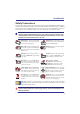
UltraMobilePC Preparing your UltraMobilePC These are only quick instructions for using your UltraMobilePC. Read the later pages for detailed information on using your UltraMobilePC. 1. Install the battery pack 2. Connect the AC Power Adapter 2 1 3 3. Remove the Tablet Pen 4. Turn ON the UltraMobilePC Extend the Tablet Pen as shown. Then Tablet Pen can be inserted in the extended Slide the power switch and release.
UltraMobilePC 10
UltraMobilePC 2. Knowing the Parts Basic sides of the UltraMobilePC NOTE: Photos and icons in this manual are used for artistic purposes only and do not show what is actually used in the product itself.
UltraMobilePC Front Side Refer to the diagram below to identify the components on this side of the UltraMobilePC. 1 2 3 12 4 11 10 5 9 8 6 7 1 Display Panel The display panel functions the same as a desktop monitor. The UltraMobilePC uses an active matrix TFT LCD, which provides excellent viewing like that of desktop monitors. Unlike desktop monitors, the LCD panel GRHV QRW SURGXFH DQ\ UDGLDWLRQ RU ÁLFNHULQJ VR LW LV HDVLHU RQ WKH H\HV Use a soft cloth without chemical liquids (use plain wate
UltraMobilePC 5 Page Up & Page Down The Page Up and Page Down buttons act the same way as those on a keyboard. 6 UltraMobilePC Settings Button The UltraMobilePC settings button bring up an easy menu to customize the UltraMobilePC to your desire. 7 Status Indicators Status indicators represent various conditions. Details are described in section 3. 8 Audio Speaker The built-in speaker system allows you to hear audio without additional attachments.
UltraMobilePC Right Side Refer to the diagram below to identify the components on this side of the UltraMobilePC. 1 2 3 4 5 6 LAN Port (disabled when using PortBar) 1 The RJ-45 LAN port with eight pins is larger than the RJ-11 modem port and supports a standard Ethernet cable for connection to a local network. The built-in connector allows convenient use without additional adapters. Note: An active LAN cable must be connected in order for Windows device manager to detect the built-in LAN.
UltraMobilePC 3 4 2.0 USB Port (2.0/1.1) The USB (Universal Serial Bus) port is compatible with USB 2.0 or USB 1.1 devices such as keyboards, pointing devices, cameras, hard disk drives, printers, and scanners connected in a series up to 12Mbits/sec (USB 1.1) and 480Mbits/sec (USB 2.0). USB allows many devices to run simultaneously on a single computer, with some peripherals acting as additional plug-in sites or hubs.
UltraMobilePC Top Side Refer to the diagram below to identify the components on this side of the UltraMobilePC. 1 1 AV-OUT 2 3 4 5 6 7 8 AV-OUT Audio/Video output port for connection to analog audio/video devices such as televisions or video recorders. 2 3 2.0 HOLD USB Port (2.0/1.1) The USB (Universal Serial Bus) port is compatible with USB 2.0 or USB 1.
UltraMobilePC 6 WIRELESS Wireless Switch Enables or disables the built-in wireless LAN and Bluetooth (selected models). When enabled, the wireless status indicator will light. Windows software settings are necessary before use. 7 LOGIN LOGIN Button The LOGIN button sends a [Ctrl][Alt][Del] keyboard combination to the operating system to show Windows Security for logging in/off, locking, shutting down, showing task manager, or changing passwords.
UltraMobilePC Left Side Refer to the diagram below to identify the components on this side of the UltraMobilePC. 1 1 Mini-USB Port (Type A) 2 LOCK UNLOCK PrtSc F1 F2 F3 F4 F5 F6 F7 F8 F9 F10 F1 F11 F12 F1 SysRq Pause Break PgUp The mini-USB (Universal Serial Bus) port is for connection to the optional external USB keyboard. 2 Wrist strap hook The wrist strap hook is for use with the wrist strap to prevent accidentally dropping the UltraMobilePC when holding it in your hands.
UltraMobilePC Bottom Side Refer to the diagram below to identify the components on this side of the UltraMobilePC. 1 1 2 3 Battery Lock - Spring The spring battery lock is used to keep the battery pack secured. When the battery pack is inserted, it will automatically lock. To remove the battery pack, this spring lock must be held in the unlocked position.
UltraMobilePC Back Side Refer to the diagram below to identify the components on this side of the UltraMobilePC. 1 2 3 4 1 GPS Antenna (built-in) 1.3M PIXELS 7KH *36 DQWHQQD FDQ EH ÁLSSHG XS IRU EHWWHU UHFHSWLRQ RU ÁLSSHG GRZQ when not in use. The GPS antenna is used by the built-in SiRF3 GPS chipset. Together, the built-in GPS can be used with various navigation software applications without additional attachments.
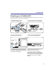
UltraMobilePC Back Side (cont.) 7KH VXSSRUW VWDQG DQG *36 DQWHQQD FDQ ÁLS RXW DV LOOXVWUDWHG ZKHQ XVLQJ WKHP )OLS WKHP back in for easy handling or transport.
UltraMobilePC 22
UltraMobilePC 3. Getting Started Using AC Power Using Battery Power Powering ON the UltraMobilePC Checking Battery Power Restarting or Rebooting Powering OFF the UltraMobilePC Status Indicators NOTE: Photos and icons in this manual are used for artistic purposes only and do not show what is actually used in the product itself.
UltraMobilePC Power System Using AC Power The UltraMobilePC power is comprised of two parts, the power adapter and the battery power system. The power adapter converts AC power from a wall outlet to the DC power required by the UltraMobilePC. Your UltraMobilePC comes with a universal AC-DC adapter. That means that you may connect the power cord to any 100V-120V as well as 220V-240V outlets without setting switches or using power converters.
UltraMobilePC Using Battery Power The UltraMobilePC is designed to work with a removable battery pack. The battery pack consists of a set of battery cells housed together. A fully charged pack will provide several hours of battery life, which can be further extended by using power management features through the BIOS setup. Additional battery packs are optional and can be purchased separately through a retailer.
UltraMobilePC Powering ON the UltraMobilePC The UltraMobilePC’s power-ON message appears on the screen when you turn it ON. If necessary, you may adjust the brightness by using the hotkey. If you need to run the BIOS 6HWXS WR VHW RU PRGLI\ WKH V\VWHP FRQÀJXUDWLRQ SUHVV >) @ XSRQ ERRWXS WR HQWHU WKH %,26 Setup. If you press [Tab] during the splash screen, standard boot information such as the BIOS version can be seen.
UltraMobilePC Checking Battery Power The battery system implements the Smart Battery standard under the Windows environment, which allows the battery to accurately report the amount of charge left in the battery. A fullycharged battery pack provides the UltraMobilePC a few hours of working power. But the DFWXDO ÀJXUH YDULHV GHSHQGLQJ RQ KRZ \RX XVH WKH SRZHU VDYLQJ IHDWXUHV \RXU JHQHUDO ZRUN habits, the CPU, system memory size, and the size of the display panel.
UltraMobilePC Charging the Battery Pack Before you use your UltraMobilePC on the road, you will have to charge the battery pack. The battery pack begins to charge as soon as the UltraMobilePC is connected to external SRZHU XVLQJ WKH SRZHU DGDSWHU )XOO\ FKDUJH WKH EDWWHU\ SDFN EHIRUH XVLQJ LW IRU WKH ÀUVW WLPH A new battery pack must completely charge before the UltraMobilePC is disconnected from external power.
UltraMobilePC Power Management Modes The UltraMobilePC has a number of automatic or adjustable power saving features that you can use to maximize battery life and lower Total Cost of Ownership (TCO). You can control some of these features through the Power menu in the BIOS Setup. ACPI power management settings are made through the operating system.
UltraMobilePC Status Indicators Power Indicator The power indicator lights when the UltraMobilePC is turned ON and blinks slowly when the UltraMobilePC is in the Suspend-to-RAM (Standby) mode. This indicator is 2)) ZKHQ WKH 8OWUD0RELOH3& LV WXUQHG 2)) RU LQ WKH 6XVSHQG WR 'LVN +LEHUQDWLRQ mode. Battery Charge Indicator The battery charge indicator shows the status of the battery’s power as follows: ON: The UltraMobilePC’s battery is charging when AC power is connected.
UltraMobilePC 4. Using the UltraMobilePC Display Calibration Connections Network Connection Wireless LAN Connection Bluetooth Wireless Connection Power Management Modes Fingerprint Scanner GPS Software NOTE: Photos and icons in this manual are used for artistic purposes only and do not show what is actually used in the product itself.
UltraMobilePC Display Calibration MS Windows Vista 1. Launch Control Panel from Windows 2. Double click Tablet PC Settings icon. Start. 3. Click the Calibrate button on the “General” 4. Carefully tap the center of each cross hair page. that appears near each corner to complete the calibration process.
UltraMobilePC Display Calibration (cont.) MS Windows XP 1. Double click the TouchSet Utility icon on 2. Or launch TouchSet Utility through Winthe desktop. dows Start. 3. Click the Calibration tab and click the Cali- 4. Carefully tap the center of each cross hair brating Now button. that appears near each corner to complete the calibration process.
UltraMobilePC Connections Network Connection Connect a network cable, with RJ-45 connectors on each end, to the modem/network port on the UltraMobilePC and the other end to a hub or switch. For 100 BASE-TX / 1000 BASE-T speeds, your network cable must be category 5 or better (not category 3) with twisted-pair wiring. If you plan on running the interface at 100/1000Mbps, it must be connected to a 100 BASE-TX / 1000 BASE-T hub (not a BASE-T4 hub). For 10Base-T, use category 3, 4, or 5 twisted-pair wiring.
UltraMobilePC Wireless LAN Connection (on selected models) The optional built-in wireless LAN is a compact easy-to-use wireless Ethernet adapter. Implementing the IEEE 802.11 standard for wireless LAN (WLAN), the optional built-in wireless LAN is capable of fast data transmission rates using Direct Sequence Spread Spectrum (DSSS) and Orthogonal Frequency Division Multiplexing (OFDM) technologies on 2.4GHz/5GHz frequencies. The optional built-in wireless LAN is backward compatible with the earlier IEEE 802.