
User Manual
Vista
GPS Chipset
An @Road proprietary chipset comprised of two chips, GPS Signal Processing ASIC (VGP-12)
and RF ASIC (VRF-12).
GPS Signal Processing ASIC
VGP-12 is the GPS Digital ASIC that combines twelve satellite correlator channels with other
GPS system control peripherals. VGP-12 is designed to work with L1-CA dual bit down converter
RF ASIC chip, VRF-12 by @Road.
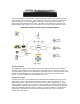
VGP-12 is designed to process up to 4 VRF-12 down converted signals for applications requiring
multiple antenna connections. Concurrent processing of multiple antenna signals:
a) Delta phase measurements between down converted signals.
b) Independently down converted signal processing,
c) Cross strapping for redundancy.
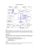
VGP-12 contains six types of functional blocks: A CPU interface, GPS clock controller, GPS
correlator channels with their common control logic, receiver magnitude gain control, 8-bit parallel
port and two serial ports (UART).
The VGP-12 device is packaged in 100-pin PQFP and operates from 2.7 to 3.7 volt supply.
RF ASIC
VRF-12 has an integrated dual conversion front end for a Global Positioning System (GPS)
receiver application. The input is L1 (1575.42 Mhz) GPS signal. Output is a down converted,
band pass 2-bit quantized signal, ready for digital processing.
VRF-12 is a dual conversion super-heterodyne receiver featuring an on-chip low noise amplifier
(LNA), an image-reject front end, voltage-controlled-oscillator (VCO) with on-chip resonator,
phase lock loop (PLL) synthesizer, automatic gain control (AGC), reference oscillator, 2-bit A/D
and power control.
VRF-12 device is packaged in 48-pin TQFP and operates from 2.7 to 3.7 volt supply.
CDPD Modem
The CDPD modem is used to transmit location specific information from the iLM2500 to @Road’s
Server. The data is sent over periodic intervals defined by users and governed by different cost
plans. The CDPD modem interface is through the UART from the Digital ASIC, VGP-12. The
supply power to the modem can be turned ON/OFF via CPU control.
RTC and System Controller
A DS1670E IC from Dallas Semiconductor is used for real time clock and NVRAM control,
including automatic battery backup. It also has three A/D inputs. The CPU uses an 8-bit A/D
Converter to monitor supply voltage, temperature and GPS antenna.
External Interfaces
There are two external interface connectors available. One 26 pin for data and one 16 pin for
power and high current I/O interface. The supported interfaces are Data Port1, Data Port2, PTO
I/Os, Relay Drivers, Nextel Modem, and power I/Os. There are also two RF connectors for GPS
and CDPD Modem antennas.
Data Port1
Data Port1 is solely used for the iDT, manufacturing, configuring, and debugging.
Data Port2
Data Port2 can be treated as the auxiliary data port. It interfaces with external devices such as a
temperature sensor, smart card reader, printer, barcode scanner and magnetic stripe reader.