
User Manual

PTO I/Os
These I/Os allow a customer to monitor up to 4 contact-based switch events. The iLM can be
programmed to transmit additional points when a switch transition occurs. Each time a switch
transition, ON!OFF or OFF!ON occurs, an update is transmitted to the server.
Relay Drivers
There are two +12VDC relay drivers that can be used to turn ON/OFF the external relays.
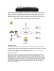
Nextel Modem (Optional)
Allows the user to interface an iLM2500 with an iDEN700 Nextel phone. The phone is data
capable for communicating with the network server.
RF Connector
An SMA jack is used for GPS antenna connection a MMCX Coaxial connector is used for CDPD
antenna connection.
Airlink Data Rate
Rate: 19200 bits per second
Transmission Standard (CDPD System Specification Part 401, Section 4.5)
Frequency Range
Transmit: 824 MHz - 849 MHz
Receive: 869 MHz – 894MHz
RF Power
Class III: variable 0.006 to 0.6 Watt EPR
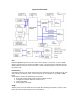
Power Supply
+12VDC from the vehicle is the main input power source to the iLM2500. Another alternate
source is the backup battery. With the backup battery installed, the iLM will continue to operate if
main power is absent or the voltage level falls below +12VDC. The iLM uses the input power to
provide two +12VDC supply lines. These supply lines provide power to external devices via RJ45
connector Data1 and Data 2. These lines can be switched ON/OFF by the CPU.
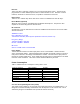
Power Consumption
Table 1: iLM2500 Current consumption in mA @ VDD = 3.3V
Mode of operation Normal (MAX) Standby
CPU 75 3
Digital ASIC 110 30
RF ASIC 43 4
Flash memory 7 0.0005
SRAM memory 40 0.0005
Peripherals ~20 ~15
Total 295 52
Over the Air Programming Function (OTAP)
This unique feature enables us to reprogram an iLM with new firmware, via CDPD modem. It is
designed for maximum flexibility and minimum code development on the network side. This is
achieved by using the standardized TFTP (Trivial File Transfer Protocol).