
Installation Instructions


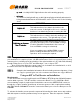
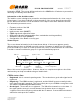

Table Of Contents

FCC ID: PDCILM272XSW 6/19/02 DRAFT
Confidential Information 4 PN: 900-002x-000
© 2002 At Road, Inc.
All Rights Reserved
Use a voltmeter to verify voltage and hook wires as indicated below.
Black
Ground
Red
(fused, 3 Amps)
to vehicle battery, unswitched (+), this wire must
see at least 10 volts at all times, if not the unit will reset continually and send inaccurate
information
White (fused, 3 Amps) To true ignition, 12V switched, there must be
12 volt power in the “on”, “start”, and “run”
position.
All connections at the column harness must be made by either soldering bare wire to bare
wire or using the poke and wrap method.
Note: T-taps, scotch locks, and like connectors are
not permitted and must not be used to tie the iLM to its power source.
4
44
4
)
))
)
Position GPS Antenna for Optimum Performance
Position GPS Antenna for Optimum PerformancePosition GPS Antenna for Optimum Performance
Position GPS Antenna for Optimum Performance
To ensure best reception, install the GPS antenna in a location that provides a clear sky view (greater than a 90 degree
angle view of the sky)
SMALL VEHICLE
SMALL VEHICLESMALL VEHICLE
SMALL VEHICLE
(A) BEST
(A) BEST(A) BEST
(A) BEST –
––
– Top of vehicle
(B) Option
(B) Option (B) Option
(B) Option –
––
–
Dashboard of vehicle (C) Option
(C) Option(C) Option
(C) Option –
––
– Rear brake light compartment (must be
non-metallic)
Could be on the dashboard or hidden Place under the rear brake light.
under non-metallic dashboard. The Can be accessed through the trunk.
antenna must face toward the sky. Only recommended when the rear window has a
steep slope.
LAR
LARLAR
LARGE VEHICLE
GE VEHICLEGE VEHICLE
GE VEHICLE