585-310-216 Issue 2 December, 1995 Ta INTUITYTM Integration with NEC® NEAXTM 2400 Switch Graphics © AT&T 1988
Blank Page
Contents 1 2 Table of Contents iii About This Document xi ■ Intended Audiences xii ■ Prerequisite Skills or Knowledge xii ■ Document Organization xii ■ How to Use this Document xiv ■ Conventions Used xiv ■ Trademarks and Service Marks xvi ■ Related Resources xvii ■ How to Make Comments About This Book xviii Introduction and Requirements for Integration 1-1 ■ Safety Considerations 1-3 ■ Factory Assembled Systems 1-3 ■ Determining the Placement of the SID 1-4 ■ System
Contents Scroll Item Edit Forms Edit Form Keys Edit Form Help Functions Action Forms 3 4 5 iv Switch Integration Planning 2-6 2-7 2-8 2-8 3-1 ■ Determining the Number of Voice Mail Ports 3-2 ■ Setting the Message Desk Number 3-2 ■ Setting the Calling Party Identification Pad String 3-3 ■ Setting the Message Waiting Indicator Pad String 3-3 ■ Setting the Message Waiting Indicator Feature 3-3 ■ Determining the Message Center Interface Baud Rate 3-3 ■ Determining the SMDI Baud Rate
Contents 6 7 Administering the INTUITY System for the NEAX Integration 6-1 ■ Administering the Switch Link Administration Screen 6-2 ■ Stopping and Restarting the Voice System 6-6 ■ Administering the System Translation Screen 6-7 NEAX 2400 Switch Administration 7-1 ■ Administer Analog Voice Mail Ports 7-2 ■ Assign Voice Mail Extensions to a UCD Group 7-6 Setting Up a UCD Overflow Group ■ 8 7-8 Configuring the Message Center Interface Link 7-10 Administer the Message Waiting Lamp
Contents 9 Acceptance Tests ■ 10 B C vi 9-2 Task 1: Forward Calls for Ring-No-Answer 9-2 Task 2: Forward Calls for Busy Conditions 9-3 Task 3: Forward Subscribers for All Calls 9-4 Cut-to-Service ■ A Administer the Test Subscribers 9-1 Administer the Subscriber Telephones 10-1 10-2 Task 1: Forward Subscribers for Ring-No-Answer 10-2 Task 2: Forward Calls for Busy Conditions 10-3 Task 3: Forward Subscribers for All Calls 10-4 Troubleshooting and Error Logs A-1 ■ Switch Integratio
Contents Message Retrieval in Lodging Systems without AUDIX C-2 Message Retrieval in Systems Shared with AUDIX C-2 Retrieval from the AUDIX Ap plication Retrieval from the Lodging Ap plication Alternate Message Retrieval Method C-2 C-2 C-2 ■ Voice Mail Administration C-3 ■ Call Coverage Path C-4 ■ Do-Not-Disturb C-5 ■ Cut-to-Service C-5 ■ Gradual Cut-to-Service C-5 One-Step Cut-to-Service C-6 Summary C-6 ABB Abbreviations ABB-1 GL Glossary GL-1 IN Index IN-1 Issue 2 Decemb
Contents viii Issue 2 December 1995
About This Document INTUITY™ Integration with NEC® NEAX™ 2400 Switch contains installation and administration instructions for integrating a NEAX 2400 MCI switch with an INTUITY system. The document contains instructions or information on the following topics.
About This Document Intended Audiences This document is designed primarily for the on-site AT&T-certified services technician, the customer’s technical personnel, and the customer’s NEAX services technician. Use the document to install INTUITY system integration-required hardware and software, perform acceptance tests, and perform cut-to-service. The customer or the customers’ switch vendor should use the document when performing switch administration tasks and other customer required tasks.
About This Document ■ Chapter 4, "Hardware Installation", describes the installation of the SID, cables to the switch, and cables to the INTUITY system. This chapter only contains information for installing the hardware components required for the integration. ■ Chapter 5, "Installing SID Software on the INTUITY System", contains instructions for installing the INTUITY system software required to integrate with the NEAX 2400 switch.
About This Document How to Use this Document This document provides additional information you need to know when integrating a NEAX switch with an INTUITY system.
About This Document Begin at the Administration menu, and select the following sequence: > Voice System Administration > Voice Equipment In this example, you would first access the Administration menu. Then you would select the Voice System Administration option to display the Voice System Administration menu. From that menu, you would select the Voice Equipment option to display the Voice Equipment screen.
About This Document Trademarks and Service Marks The following trademarked products may be mentioned in this book: Product Name Company 5ESS™ Registered trademark of AT&T AT™ Trademark of Hayes Microcomputer Products, Inc. AUDIX® Registered trademark of AT&T BT-542B™ Trademark of BusLogic Inc. COMSPHERE® Registered trademark of AT&T Paradyne Corp.
About This Document Related Resources In addition to this book, you may need to reference the following books: Title Order Number INTUITY System Description 585-310-211 INTUITY AUDIX Feature Descriptions 585-310-212 INTUITY Documentation Guide 585-310-540 Migration to the INTUITY System 585-310-602 INTUITY New System Planning 585-310-603 INTUITY MAP/5 Hardware Installation 585-310-146 INTUITY MAP/5 Installation Checklist 585-310-147 INTUITY MAP/40 Hardware Installation 585-310-138 INTUITY
About This Document Title Order Number INTUITY AUDIX Announcement Customization- French Canadian 585-310-538 AUDIX Administration and Data Acquisition Package 585-302-502 A Portable Guide to Voice Messaging 585-300-701 Voice Messaging Quick Reference 585-300-702 Multiple Personal Greetings Quick Reference 585-300-705 Voice Messaging Wallet Card 585-300-704 Outcalling Quick Reference 585-310-721 Voice Messaging Business Card Stickers 585-304-705 Voice Messaging Subscriber Artwork Package
Introduction and Requirements for Integration 1 This chapter describes and defines requirements for the NEC NEAX 2400 MCI switch integration with an INTUITY Messaging System. The chapter includes diagrams and checklists that show the configuration for INTUITY Messaging System. To create an integrated environment between INTUITY Messaging System and an NEC NEAX 2400 MCI switch, AT&T uses an electronic box called a Switch Integration Device (SID).
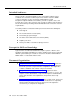
Introduction and Requirements for Integration 1. Incoming call sent to the 1st extension of the UCD Group. The extension is busy. BUSY 5001 2. The call Hunts BUSY to the next 5002 extension which is also busy. OPEN 3. The call finds an open extension. The call is completed using the open extension. 5003 Completed Call 5004 Figure 1-1 UCD Group Hunting Process By administering the UCD group, you enable the switch to support the following features.
Safety Considerations Safety Considerations ! CAUTION: Electrostatic discharge damages electronic equipment. Do not touch any electronic component until you properly ground yourself. To prevent damage to the equipment and yourself, follow these precautions: ■ Familiarize yourself with the procedures necessary to prevent electrostatic damage to equipment. ■ Shut off all power and remove all cables from equipment. ■ Properly ground a work mat and wrist strap. ■ Place the equipment on the work mat.
Introduction and Requirements for Integration Determining the Placement of the SID The Switch Integration Device (SID) and the MAP/5, MAP/40, or MAP/100 represent local devices. Place the SID and the MAP in the same area and close enough together so the RS-232 cable supplied with the SID can connect to the computer. During installation, the AT&T technician will place the SID and the MAP in the location specified by the customer.
System Configuration System Configuration The Intuity system connects to the NEAX switch through a Switch Integration Device (SID). Figure 1-2 shows you the connections between an Intuity system and a NEAX switch through the multi-port serial card. Figure 1-3 shows you the connections between an Intuity system on a MAP/5 platform and a NEAX switch through COM1.
Introduction and Requirements for Integration Figure 1-3 Connections through the COM 1 Serial Port for an Intuity Integration with a NEAX Switch (MAP/5 only) 1-6 Issue 2 December 1995
System Configuration Intuity System Required Hardware Table 1-1 lists the hardware components required on the Intuity system for the NEAX integration. Table 1-1. Intuity System Hardware Components Required for the Integration Component AT&T Supplied Description MAP/5, MAP/40, or MAP/100 Hardware platform that operates the Intuity system software X IVC6 cards Integrated Voice Processing (IVC6) cards used for voice port connections. May have a maximum of 11 cards.
Introduction and Requirements for Integration Switch Integration Device Required Hardware Table 1-1 lists the required SID components for the integration. Table 1-2.
System Configuration NEC NEAX 2400 MCI Hardware The customer must provide the correct switch and related components as described in Table 1-3. All required items should be available and configured before an AT&T technician arrives to install the INTUITY system. The INTUITY system integrates only with the NEC NEAX 2400 switch and related components described in Table 1-3. Table 1-3.
Introduction and Requirements for Integration In addition to the hardware and software listed in Table 1-3, you must provide the following administration on the NEAX 2400. ■ Program the PA-16LCQ analog ports to provide an adequate loop current disconnect, or wink. The PA-16LCQ card provides a default value of approximately 128ms wink. The wink can be increased to approximately 448ms with a firmware upgrade from NEC.
Switch Integration Device Basics 2 Before you attempt to operate and administer the Switch Integration Device (SID) and integrate an NEC NEAX 2400 MCI switch with an INTUITY System, you need to understand the hardware components of the SID and how to use the device. The information in this chapter explains the basic components of the SID and how to use the system forms or screens. The chapter covers the following topics.
Switch Integration Device Basics The Switch Integration Device Hardware Before you use the SID, you need to understand each hardware component. Read the descriptions below of each component and refer to Figure 2-1. to locate the component. Front Panel LCD display A two-line, 40-character, backlighted LCD display screen used to show all menus and information on the SID. Diagnostic lights LED lights used to indicate and trace possible problems in the SID.
The Switch Integration Device Hardware Func Mode ABC 2 3 JKL MNO PRS TUV WXY 7 8 9 * 0 # 4 LCD DISPLAY Status VM PBX COM APP Enter DEF 1 GHI 5 6 KEYPAD DIAGNOSTIC LIGHTS 25 Pin 25 Pin Power Switch Link B Power Cord Outlet (Male) Diag Net B Link A Net A Modem Line B Line A 115-230V AC 50/60 Hz (Fan Outlet) Figure 2-1.
Switch Integration Device Basics The Switch Integration Device Software The SID contains software that allows you to perform installation, configuration, and diagnostic tasks by using the keypad and the LCD screen. As you administer the SID, you use three types of forms or screen d isplays. Each type of form has a specific task. ■ Menu Forms — used to select one of several options. ■ Edit Forms — used to enter information into the SID’s configuration.
The Switch Integration Device Software Example: If you wanted option 4, SETUP, from the MCI User Interface Main Menu shown in Figure 2-2., press 4 on the keypad. After you press 4, you see the SETUP form appear on the screen as shown in Figure 2-3.. SETUP 1-Params 2-Ports 3-Clear 4-Advanced Figure 2-3. The Setup Form The SID uses menus to organize all options and functions into categories. Menus also permit the user to navigate easily through the forms by pressing one or more keys.
Switch Integration Device Basics Single Item Edit Forms On a Single Item Edit form, you must enter one piece of information or answer one question. Figure 2-4. shows you an example of a single item edit form, the SETUP form. On the form, you need to enter the number of ports assigned to the INTUITY System. In this example, you enter the appropriate value using the digits on the keypad and press ENTER . SETUP Figure 2-4.
The Switch Integration Device Software In the example, you use the MCI form to set the baud rate for the MCI link. You can set the baud rate to specific values between 300 and 9600 baud. On the form you see a default value of 1200. To see the other options, you press the left arrow key to decrease the baud rate or press the right arrow key to increase the rate. When you find the rate you want, press ENTER to confirm your choice.
Switch Integration Device Basics Edit Form Help Functions Edit forms allow you to actively access help screens. To access the help screen, press MODE at any edit form. The SID places the help screen on the LCD display. The SID retains any information you may have entered on the edit form and places the edit form with your information back on the display when you exit the help screen. You do not lose any information. Most help screens appear as shown in Figure 2-7.
The Switch Integration Device Software All action forms use the same keys on the keypad to perform functions and make selections. The table below shows you what keys to use with the action forms. Key Action 1,2,3,4,5,6,7,8,9,0 No action *,# No action Func Return to main menu Mode Help for Action Form Arrows No action Enter No action You have read the basic information necessary to integrate and INTUITY System with an NEC NEAX 2400 MCI switch.
Switch Integration Device Basics 2-10 Issue 2 December 1995
Switch Integration Planning 3 Before you implement the NEC NEAX 2400 Message Center Interface (MCI) integration with an INTUITY System, you must plan the process. This chapter provides worksheets and information to help you plan and record the integration. You use the worksheets later to complete the switch integration process.
Switch Integration Planning Determining the Number of Voice Mail Ports You must specify the number of voice mail ports for the Switch Integration Device (SID) to support and monitor. The number of ports for the SID is the same as the number of ports assigned to the INTUITY System. The maximum number of supported lines depends on the switch software level. Your switch software must sup port the UCD overflow feature. The SID assigns a default value of 140 to this field.
Setting the Calling Party Identification Pad String Setting the Calling Party Identification Pad String The Message Center Interface (MCI) protocol, used by the NEAX 2400 switch to communicate with the SID, provides calling and called party information consistent with the dial plan administered on the switch. The SID operates on Simplified Message Desk Interface (SMDI) protocol which uses a seven-digit field.
Switch Integration Planning Determining the SMDI Baud Rate You must set the baud rate for the Simplified Message Desk Interface (SMDI) link. The SID provides baud rate selections of 300, 1200, 2400, and 9600 baud and sets a default of 1200 baud. AT&T recommends that you use a baud rate of 2400. Write the SMDI link baud rate on line 7 of Worksheet A. Determining the Extension/Logical Terminal Number Plan On the INTUITY System, you assign a channel to each extension to allow for switch communications.
Determining the Extension/Logical Terminal Number Plan Worksheet B: Extension/LTN Plan Extension LTN Extension LTN 1 2 3 4 5 6 7 8 9 10 11 12 13 14 15 16 17 18 19 20 21 22 23 24 25 26 27 28 29 30 31 32 33 34 35 36 37 38 39 40 41 42 43 44 45 46 47 48 49 50 51 52 53 54 55 56 57 58 59 60 61 62 63 64 Issue 2 December 1995 3-5
Switch Integration Planning 3-6 Issue 2 December 1995
Hardware Installation 4 This chapter describes the hardware and cable installation tasks required to integrate the NEAX 2400 MCI switch with an INTUITY System through a switch integration device (SID).
Hardware Installation Connect an Analog Line to the Modem This task should be performed by the AT&T installation technician and the customer or the customer’s switch technician. The SID contains an internal modem that allows for remote site access and maintenance. You must connect an analog line from the switch to the remote modem to allow for maintenance. Connect the analog line to the switch before the AT&T installation technician arrives.
Connect the MCI Line to the Switch Connect the MCI Line to the Switch The customer or the customer’s switch technician must complete this task. AT&T does not assume responsibility for any cable connections to the NEAX 2400 switch. The NEAX 2400 switch communicates with the SID through a Message Center Interface (MCI) link. To connect the link, the customer must provide a cable to connect to the MCI digital port and also provide an A25B cable to connect to the MCI cable.
Hardware Installation Use the following instructions to connect the MCI line to the NEAX 2400 switch. 1. Set the MCI I/O port (PN PAIO02) at the same baud rate as the SID, 2400 baud. Use Table 4-1 to set the DIP switches on the MCI I/O port. NOTE: To set the baud rate for the MCI Link, you must set switches 1, 2, and 3 in a specific combination. For example, to set the baud rate at 2400BPS, set switch 1 to ON, switch 2 to OFF, and switch 3 to OFF. Table 4-1.
Connect the MCI Line to the Switch 2. Set the parity of the MCI link to even and the word length to 7 bits. Use Table 4-2 and Table 4-3 to set the DIP-switches on the MCI I/O card in the switch. NOTE: If you need more information for setting the baud rate, parity, and DIP-switches on the NEAX 2400 MCI port, refer to the documentation supplied with your switch or contact your switch service representative. Table 4-2.
Hardware Installation Table 4-3.
Connect the MCI Cable to the A25B Cable Table 4-4. Cable Pinouts NEAX 2400 25 Pair RS-232 Function RS-232 Pin Number Port 0 Violet/Slate Frame Ground 1 Blue/White Transmit Data 3 Orange/White Receive Data 2 Blue/Red Signal Ground 7 Violet/Slate Frame Ground 1 Green/Black Transmit Data 3 Brown/Black Receive Data 2 Green/Yellow Signal Ground 7 Port 1 Proceed to the next section.
Hardware Installation Connect the Null Cable and the Y-Cable to the SID The AT&T installation technician, the customer, or the customer’s switch technician must complete this task. The NEAX 2400 switch communicates with the SID through a Message Center Interface (MCI) link. To connect the SID to the MCI digital port, you must connect a Null cable and a Y-cable to the SID. Use the following instructions to connect the cables to the SID. 1.
Connect the SID to the INTUITY System Connect the SID to the INTUITY System This task requires you to connect the 6’ RS-232 cable to the SID and to the INTUITY System and should be completed by the AT&T installation technician. The cable connects directly to the SID and connects to the INTUITY system through a 6-to-25-pin adaptor and a modular cable. Use the following instructions to connect the SID to the INTUITY System. 1. Connect the 25-pin RS-232 connector to Link A on the back of the SID.
Hardware Installation 4-10 Issue 2 December 1995
Installing SID Software on the INTUITY System 5 This chapter provides procedures for installing the SID software on the INTUITY system. NOTE: Before you install the SID software, make sure that the voice system and maintenance software are installed. Also, ensure that no other switch software is already installed. To install the SID software, perform the following 4 procedures: 1. Stop the voice system. 2. Load the SID software. 3. Start the voice system. 4. Turn on INTUITY AUDIX transfer feature.
Installing SID Software on the INTUITY System Stop the Voice System Before you can load the SID software, you must stop the voice system. ! CAUTION: All calls in progress will be disconnected. Use the following procedure to stop the voice system. 1. Login as craft. 2. Press to accept the AT386 default. ENTER You see the INTUITY Administration menu. 3.
Load the SID Software Load the SID Software 1. Starting at the INTUITY Administration menu, select the following series of menu options: > Customer/Services Administration >System Management >UNIX Management >Software Install After you select the last option, you see the Software Install menu, as shown in Figure 5-1. Figure 5-1.
Installing SID Software on the INTUITY System 2. Select Floppy drive from the Software Install menu. The system responds: Insert diskette into Floppy Drive 1. Type [go] when ready or [q] to quit: (default: go) 3. Insert SID Switch Integration Package Disk 1 of 2 into the 3.5” floppy drive. 4. Press ENTER to install the software. The system responds: Installation in progress. Do not remove the diskette. The following packages are available: 1 sid INTUITY SID Switch Integration Package (486) 1.
Load the SID Software Figure 5-2. Switch Link Administration Screen with System Defaults 11. Use Table 5-1 to enter the correct values in each field on the Switch Link Administration screen.
Installing SID Software on the INTUITY System Table 5-1. Switch Link Administration Screen Entries Field Data link test number Description Indicates the test number sent to the switch to verify whether the switch is active. Setting: A 7- or 10-digit number that is not an inservice extension number. The number of digits must agree with the setting for the dialstring size set on the SID. Refer to Chapter 3, "Switch Integration Planning", to find the dialstring size.
Load the SID Software 12. Press SAVE (F3). After you press the key, you receive a confirmation message as shown in Figure 5-3. The message tells you that the serial port was registered successfully and that you need to start the voice system Figure 5-3 13. Press Switch Link Administration Confirmation Message CANCEL (F6). You see the Switch Link Administration screen. 14. Press CANCEL (F6) again. You see several messages indicating that the installation is still running.
Installing SID Software on the INTUITY System Start the Voice System Restart the voice system for the INTUITY system to accept and process calls. Use the following procedure to start the voice system. 1. Starting at the INTUITY Administration menu, select the following series of menu options: > Customer/Services Administration > System Management > System Control >Start Voice System You see messages indicating that the voice system is being restarted.
Administering the INTUITY System for the NEAX Integration 6 This chapter describes how to administer the INTUITY system for integration with the NEAX switch. To integrate with the NEAX switch, the INTUITY system needs to know specific information about how the integration is set up, such as the serial port and baud rate being used.
Administering the INTUITY System for the NEAX Integration Administering the Switch Link Administration Screen During the NEAX software installation process, the values for the Switch Link Administration screen were administered. You need to change the default settings on this screen. Use the following procedure to change the settings. 1. Login as craft. 2. Press ENTER to accept the AT386 default. You see the INTUITY Administration menu as shown in Figure 6-1. Figure 6-1. INTUITY Main Menu 3.
Administering the Switch Link Administration Screen Figure 6-2 Switch Interface Administration Menu 4. Select Switch Link Administration from the menu. After you select the option, you see the Switch Link Administration screen as shown in Figure 6-3. Figure 6-3 Switch Link Administration Screen 5. Use Table 6-1 to enter the correct values in each field on the Switch Link Administration screen.
Administering the INTUITY System for the NEAX Integration Table 6-1. Switch Link Administration Screen Entries Field Data link test number Description Indicates the test number sent to the switch to verify whether the switch is active. Setting: A 7- or 10-digit number that is not an inservice extension number. The number of digits must agree with the setting for the dialstring size set on the SID. Refer to Chapter 3, "Switch Integration Planning", to find the dialstring size.
Administering the Switch Link Administration Screen 6. Press SAVE (F3). After you press the key, you receive a confirmation message as shown in Figure 6-4. The message tells you that the serial port was registered successfully and that you need to stop and restart the voice system Figure 6-4 Switch Link Administration Confirmation Message 7. Press CANCEL (F6) until you see the INTUITY Administration menu as shown in the Figure 6-1. 8.
Administering the INTUITY System for the NEAX Integration Stopping and Restarting the Voice System To execute the changes you made on the Switch Link Administration screen, use the following procedure to stop and restart the voice system. 1. Starting at the INTUITY Administration menu, shown in Figure 6-1.
Administering the System Translation Screen Administering the System Translation Screen Use the following procedure to administer the System Translation screen. 1. Starting at the INTUITY Administration menu, shown in Figure 6-1., select the following series of menu options: > Switch Interface Administration > System Translation After you select the System Translation option, you see the System Translation screen as shown in Figure 6-5. Figure 6-5. System Translation Screen 2.
Administering the INTUITY System for the NEAX Integration Table 6-2. System Translation Screen Entries Field Description Switch link type The field contains the current switch link type. You cannot change this setting. Host type The field contains the current host switch type. You cannot change this setting. Host link ID The field contains the current host link ID. You cannot change this setting.
Administering the System Translation Screen 3. Press SAVE (F3) to save you entries on the screen. After you press the key, you see the Command Output screen as shown in Figure 6-6. The message indicates that the fields were updated successfully. Figure 6-6 4. Press Command Output Screen CANCEL (F6) until you return to the INTUITY Administration menu. You have completed the procedure required on the INTUITY System.
Administering the INTUITY System for the NEAX Integration 6-10 Issue 2 December 1995
7 NEAX 2400 Switch Administration This chapter contains instructions for administering an NEC NEAX 2400 MCI switch to work with an INTUITY System. If you have another type of switch, refer to the documentation provided with that switch or the switch integration package for more information. The instructions in this chapter only explain the screen fields and information necessary to integrate the NEAX 2400 switch with an INTUITY System.
NEAX 2400 Switch Administration Administer Analog Voice Mail Ports Each voice mail port connects to the switch through an analog line. For the integration process to function, you must configure the voice mail port analog lines in the same manner as you configure analog lines for a 2500 telephone set. After configuring the ports on the switch, you must assign the analog port extension numbers on the SID configuration. You perform the SID processes in Chapter 8, "Switch Integration Device Administration".
Administer Analog Voice Mail Ports 3. Enter 6 to select the Station Data option. After you select the option, you see the Station Data Commands screen as shown in Figure 7-2.
NEAX 2400 Switch Administration 4. Enter 1 to select the Assignment of Station Data option and enter station administration information for each voice mail port. After you select the option, you see the screen as shown in Figure 7-3.
Administer Analog Voice Mail Ports 9. In the RSC (Route Restriction Class) field, you see a default value of 0. Enter the correct RSC. After you press ENTER the cursor moves to the SFC field. Contact your switch system administrator to determine if the default value is correct. 10. In the SFC (Service Feature Class) field, you see a default value of 0. Enter the correct SFC. Contact your switch system administrator for the correct SFC value. 11.
NEAX 2400 Switch Administration Assign Voice Mail Extensions to a UCD Group After administering the analog voice mail ports, you must assign the ports to a Uniformed Call Distribution (UCD) group or switch group. The first extension of a UCD group becomes the forwarding target number for the group. When a subscriber calls INTUITY System, they dial the target number of the UCD group.
Assign Voice Mail Extensions to a UCD Group 1. At the Station Data Commands Menu shown in Figure 7-2., enter 13 to select the Assignment of Station Hunting-UCD option. After you enter the selection, you see the Assignment Of Station Hunting - UCD screen as shown in Figure 7-4.
NEAX 2400 Switch Administration 5. In the second STN field, enter the second voice mail port station you need to assign to the UCD group. Using the 500, 501, 502, and 503 example, enter 501 as the second voice mail port station. 6. Repeat Step 5 until you enter all voice mail port extensions in the UCD group. The system continues to ask for voice mail port extensions until you enter the enough stations to match the CNT field. In the examples above, CNT was set to 4.
Assign Voice Mail Extensions to a UCD Group After you select the option, you see the Assignment of Ucd Overflow Group screen as shown in Figure 7-5. Assignment of UCD Overflow Group TN-A: TN-B: 1 STN-A: 1 STN-B: 500 502 TN-A, STN-A: TN-B, STN-B: Tenant Number and Station which belongs to a UCD group Tenant Number and Station Number of member station in a UCD group to be hunted in the case where the UCD designated by TN-A and STN-A happens to be busy. Figure 7-5.
NEAX 2400 Switch Administration Configuring the Message Center Interface Link Voice messaging information travels from the switch to the SID through the Message Center Interface (MCI) link. For the MCI link to function properly, you must configure the MCI data link.
Configuring the Message Center Interface Link 1. At the 2400 Maintenance Command menu, shown in Figure 7-1., enter 13 to select the Installation option. After you select the option, you see the Installation Commands menu as shown in Figure 7-6.
NEAX 2400 Switch Administration ENTER 2. Enter 1 to select the System Data option. After you press the Assignment Of Station Data screen as shown in Figure 7-7. see you Assignment of System Data SYS: 1 INDEX: SYS 28 DATA: 20 : System Data Items 1-System Data 1 2-System Data 2 3-System Data 3 TN : Tenant Number INDEX: System Data Index System Index 1 0-255 2 0-15 3 0-31 DATA : System Data (Hexa-decimal) Figure 7-7. Assignment of System Data Screen 3. Enter 1 in the SYS field.
Configuring the Message Center Interface Link If you need more information for any of the screen fields or processes described in this section, contact your switch administrator or consult the documentation supplied with your switch. Assign a Port for the Message Center Interface Link Use the instructions in this section to assign a port for the MCI link. Assigning a port tells the switch the proper port to send information to the SID through the MCI link. 1.
NEAX 2400 Switch Administration 4. Enter the port assignment number in the DATA field. Use Table 7-1 to determine the port assignment for the MCI link. To use the chart, find the port number you want to use under the Port heading. When you find the port number, find the Data value in the Data column across from the port number. One port is reserved for the MAT. The example in Figure 7-8. uses port 1 (Data 02). Table 7-1.
Configuring the Message Center Interface Link Define the Port as a Terminal You must now designate that the port assigned to the MCI link is a terminal or two-way communication port. If you do not perform this step, the switch uses the port as a printer or one-way communication port. Use the following instructions to define the MCI port type. 1. At the Installation Commands menu, shown in Figure 7-6., enter 1 to select the System Data option.
NEAX 2400 Switch Administration Under the Port heading, find the port number you assigned to the MCI link in the "Assign a Port for the Message Center Interface Link" section. When you find the port number, locate the index value in the Index column across from the port number. Figure 7-9. uses an index value of 117, showing that the MCI link was assigned port number 1. Table 7-2. Index Assignment Values Port Index Data 1 117 01 2 118 01 3 119 01 4 120 01 5 121 01 MAT Terminal 4.
Configuring the Message Center Interface Link Use the following instructions to configure the UCD group with the MCI link. 1. At the INSTALLATION COMMANDS menu, shown in Figure 7-6., enter 1 to select the System Data option. After you press ENTER , you see the ASSIGNMENT OF STATION DATA screen as shown in Figure 7-10.
NEAX 2400 Switch Administration 5. Look at the value in the DATA field and write the value on the following line Current DATA value: _________ NOTE: Do not change the value in the DATA field until you consult with your switch administrator. This index contains other fields that control features not related to MCI. 6. Enter 01 in the DATA field. You have completed the NEAX 2400 MCI switch administration.
8 Switch Integration Device Administration The instructions in this chapter explain how to configure the SID to integrate with an NEAX 2400 MCI switch and an INTUITY System. The installation technician administers the SID based on NEAX switch administration information provided by the customer.
Switch Integration Device Administration Administer the Basic Parameters In Chapter 3, "Switch Integration Planning", you completed switch integration planning worksheets and determined the values for each of the basic parameters. If you did not complete the worksheets, turn to Chapter 3 and complete them now before you proceed with the instructions in this chapter. After you complete the worksheets in Chapter 3, continue with the instructions on the next page to configure the basic parameters. 1.
Administer the Basic Parameters 6. Enter the three-digit message desk number from worksheet A in Chapter 3. 7. Press to confirm the number and move to the next basic parameter edit form, the CPID PAD STRING form, as shown in the following example: SETUP CPID Pad String: 0000000 8. Press to accept the default CPID Pad String number of 0000000 and move to the next basic parameter edit form, the MWI PAD STRING form, as shown in the following example: SETUP MWI Pad String: 0000000 9.
Switch Integration Device Administration Assign Extensions and LTNs As you assign extensions and LTNs, you associate an LTN (Centrex LTN) with each analog extension number used by an INTUITY System. For each extension, you must assign the same LTN to the extension as the INTUITY System assigns to the extension. If you do not assign the same LTN, the SID does not integrate calls properly. Read the section on the AutoFill feature before you assign extensions and LTNs.
Assign Extensions and LTNs 5. Use the keypad to type an extension for the LTN. Use worksheet B as you enter LTNs and extensions. NOTE: Each VM PORT0 form contains a default LTN, starting with 0001. If you want to use the default, press ENTER to select the default and move the cursor to the Extension field. Enter the extension number for the LTN. Press ENTER to confirm the number then press to move to the next form. 6.
Switch Integration Device Administration Follow the instructions on the next page to use the AutoFill feature. 1. After accessing the first VM PORT form as instructed in the previous section of this d ocument, enter an extension number in the Extension field. The following example uses 210 as the first extension number: VM Port 1 LTN: 0001 Extension: 210__ 2. Position the cursor on the extension number you entered. 3. Press the MODE key for editor help.
Saving and Starting the Configuration Saving and Starting the Configuration After you administer the basic parameters and assign extensions and LTNs, you must save the configuration. You also can start the integration at this point, although you should perform the tasks in the “Administer Serial Data Links” section to check the default settings for the MCI and SMDI communication links. Use the following instructions to save the configuration and start the system. 1. Press FUNC on the SID keypad.
Switch Integration Device Administration starts, you see the SMDI VIEW MODE screen as shown in the following diagram. below: SMDI Idle When the SID receives calls, the screen changes to show the SMDI packet being sent to the INTUITY System. The screen appears similar to the following example: SMDI MWI: 0OP:MWI 0000202!. CPID: ..MD0010001D 0000201 ... For more information on view modes, refer to Ap pendix B, "Using Views During Integration", in this document.
Administer Serial Data Links Use the following instructions to check or correct the default settings. 1. To access the edit forms used to change the serial data links, press FUNC to access the MCI MAIN MENU. After you press the key, you see the MCI MAIN MENU as shown in the following example: NEC 1-View 2-Utils 4-Setup 5-Logs 2. Select Utils from the menu by pressing 2 3-System on the SID keypad. After you press the key, you see the UTILS menu as shown in the following example: UTILS 3.
Switch Integration Device Administration 6. To change the default value shown, press the left or right arrow key to toggle through the optional values. The value you set for the baud rate must equal the value set for the SID to the INTUITY System communication link baud rate. Do not set two different values for these links. Stop pressing the arrow keys when you find the value you want to use. NOTE: In Chapter 3 you completed worksheet A which contained lines for the MCI baud rate and the SMDI baud rate.
Changing System Parameters 12. To change the default stop bit value shown in the field, press the left or right arrow key to toggle through the optional values. Stop pressing the arrow keys when you find the stop bit value you want to use. 13. After you select a stop bit value, press to confirm your choice. ENTER 14. Press FUNC to return to the MCI MAIN MENU. If you need to reconfigure the SMDI data link, return to step 2. You have completed the MCI or SMDI configuration setup.
Switch Integration Device Administration 6. After you enter the year in the last date field, press date and move the cursor to the Time field. ENTER to confirm the 7. Enter the correct time in the format HH:MM:SS (hour:minute:second) by pressing ENTER and typing the hour, minutes, and seconds in each part of the time field. If the time shown is correct, proceed to the next step. 8. Press FUNC to return to the MCI MAIN MENU. The SID accepts and uses the information.
Special Processing for Message Waiting Lamps Special Processing for Message Waiting Lamps NOTE: The instructions in this section only can be performed by trained AT&T software specialists. The SID can buffer up to 4000 individual message waiting transactions and wait for small intervals of time to perform the transactions. Incoming calls receive a higher priority. If you use the Metrics View and discover that the SID is holding large numbers of MWL transactions you can perform one of the following actions.
Switch Integration Device Administration 1. Press FUNC to access the SETUP menu as shown in the following example: SETUP 1-Params 2-Ports 3-Clear 4-Advanced 2. Press 4 to select the Advanced option. After you press the key, you see the ADVNC screen as shown in the following example: ADVNC <- MWI Compress: OFF ->1 3. Use the left and right arrow keys to turn MWL Enhanced processing to ON. After you set enable MWL Enhanced processing, the SID automatically begins to use the feature.
Setting a Security Level The factory sets the SID to access level 1. When you first power on the SID, the unit accesses the SETUP menu and allows you to access all tools required to perform the administration tasks. You can select a security level for the SID and make the security level part of the configuration. AT&T recommends that you select security level 0 as the normal operating mode for the SID. Users only can access level 0 features, which reduces the risk of tampering by unauthorized users.
Switch Integration Device Administration 8-16 Issue 2 December 1995
9 Acceptance Tests Do not perform any tasks in this chapter until you complete the required tasks in the following appropriate documents: ■ Intuity MAP/5 Hardware Installation, 585-310-137 ■ Intuity MAP/40 Hardware Installation, 585-310-138 ■ Intuity MAP/100 Hardware Installation, 585-310-139 ■ Intuity Software Installation, 585-310-140 The installation documents explain when you must use the instructions in this chapter.
Acceptance Tests As explained in INTUITY New System Planning, 585-310-603, two test subscribers should have been administered on the switch for acceptance tests. Acceptance tests begin after you complete initial administration and administer two test subscribers on the INTUITY System. This chapter explains how to administer two test subscribers on the NEAX 2400 MCI switch for performing acceptance tests.
Administer the Test Subscribers Use the following instructions to forward an RNA call for the test subscribers. 1. Using the phone of the first test subscriber, lift the handset and listen for the dial tone. 2. Dial the access code or press the function key for forward RNA. After you perform the action, you hear a second dial tone. NOTE: If you do not know the access code or the function key for forward RNA, contact your switch administrator.
Acceptance Tests Task 3: Forward Subscribers for All Calls Use this feature to forward all calls to the INTUITY System. The switch automatically transfers the call to the UCD group administered for the INTUITY System. NOTE: The subscriber’s service feature class must contain call forward RNA SFI=7. Dterm sets may have a function key for forward on busy (FKY=2). Use the following instructions to forward all calls for acceptance tests. 1.
Cut-to-Service 10 Do not perform any tasks in this chapter until you complete the necessary cut-toservice tasks in the Cut-to-Service chapter of INTUITY System Software Installation, 585-310-140. The installation document explains when you must use the instructions in this chapter. If you have not performed the tasks in the installation document, complete the tasks now. This chapter explains how to administer the switch for the INTUITY system cut-toservice process.
Cut-to-Service Administer the Subscriber Telephones By forwarding a subscriber extension to the main extension of the UCD group, the switch sends call information over the MCI link to the SID. The SID converts the information to SMDI protocol and sends the information to the INTUITY System. A call forwarded from the switch to an INTUITY System is called an integrated call.
Administer the Subscriber Telephones You created the UCD main extension during the switch administration process in Chapter 7 of this document. The switch now forwards RNA calls to the INTUITY UCD group, creating an integrated voice mail system. Proceed to the next task. Task 2: Forward Calls for Busy Conditions Use this feature to forward calls that reach busy extensions.
Cut-to-Service Task 3: Forward Subscribers for All Calls Use this feature to forward subscribers for all calls to the INTUITY System. The switch automatically transfers the call to the UCD group administered for INTUITY service. NOTE: The subscriber’s service feature class must contain call forward RNA SFI=7. Dterm sets may have a function key for forward all calls (FKY=2). Use the following instructions to forward all calls. 1. Using the subscriber telephone, lift the handset and listen for the dial tone.
Troubleshooting and Error Logs A Appendix A provides troubleshooting information to help you isolate and correct problems that may occur with an INTUITY System integrated with the NEAX 2400 MCI switch. The problems outlined in this appendix only refer to problems related to the integration device and processes. If you do not find your problem in this appendix, refer to INTUITY Platform Administration and Maintenance, 585-310534, for more information.
Switch Integration Device Problems The SID does not power on. Possible Reason: The power cord connection may be loose or not completed. Remedy: Make sure the power cord is firmly plugged into the wall outlet and the SID. Possible Reason: The wall outlet may not have power. Remedy: Make sure the circuit breaker for the wall outlet is on. Possible Reason: The SID power switch may be set to the OFF position. Remedy: Turn the SID power switch to the ON position.
Switch Integration Device Problems Remedy: Refer to Chapter 8, "Switch Integration Device Administration", and set the baud rate correctly. Possible Reason: The baud rate for the SID-to-PBX MCI connection may not be set correctly. Remedy: Refer to Chapter 8, "Switch Integration Device Administration" and set the baud rate correctly. Calls are integrated but the message waiting lamp (MWL) does not work. Possible Reason: The MWL may not be administered correctly on the INTUITY System.
The VM LED is yellow constantly (more than 5% packet transmission error). Possible Reason: The SMDI cable is loose. Remedy: Tighten the SMDI cable connections. Possible Reason: The SMDI communications port baud rate, parity, and other settings are not correct. Remedy: Refer to Chapter 8, "Switch Integration Device Administration", for instructions on configuring the SMDI link. Possible Reason: The SMDI cable may be defective. Remedy: Replace the cable.
Error Logs Error Logs The SID accumulates and records or logs error messages. The error messages can help solve problems and trace errors. You can access the error logs on the SID if you are authorized to use security level 1 features. The error logs also are available to trained support personnel to assist with troubleshooting. Use the instructions in this section to log on to the SID and view the error logs. 1.
Read the following explanation of the error log to understand the information. 16 The error code number used by AT&T support personnel when they access the SID through the remote maintenance modem. No PBX Pkts in 60 Secs Informational text that provides a brief description of the error. In the example, the SID wrote an informational message indicating that no packets had been received from the switch in the previous 60 seconds. I A letter that indicates the error type and severity.
Error Logs Table A-1.
From time to time, you may need to purge your error logs. You can purge error logs on the SID if you have authorization to access security level 1 features. Use the following instructions to purge error logs. 1. Press FUNC to access the Main Menu. 2. Press 5 to select Logs. After you press the key, you see the Logs menu as shown in the following example: LOGS 1-View 2-Purge 0 3. Press 2 to select Purge.
Clearing Your Configuration Clearing Your Configuration When you add voice mail ports or change the switch dial plan, you may need to reconfigure the SID. In most cases, you can accomplish the task by editing the existing setup and restarting the system. If required, the SID provides the capability to restore the factory default settings. To clear your configuration and restore the factory setting, use the following instructions. 1. Press FUNC to access the Main Menu. 2.
A-10 Issue 2 December 1995
Using Views During Integration B The SID provides you with four real-time views of the integration process: ■ SMDI monitor mode ■ MCI monitor mode ■ Statistics mode ■ Metrics mode Each mode shows you different information in a common screen layout. A typical view mode appears as shown in the following example: SMDI MWI: 0OP:MWI 0000202 CPID: ..MD0010001D 0000201... View modes remain on the screen, constantly changing as calls and message waiting transactions are processed.
SMDI Monitor Mode The first option on the View menu is the SMDI monitor mode. The mode permits you to observe transactions as they occur on the SMDI data link that connects the SID to the INTUITY System. The SMDI monitor is a useful tool that provides condensed, real-time reporting of all transactions on the SMDI data link. The SMDI link connects the SID to the INTUITY System. The view is set as the default display mode for a configured SID.
SMDI Monitor Mode When transactions are being processed, the screen updates continuously. The example SMDI view screen above shows a call covered to the pilot number of the UCD group. The following descriptions explain the content of each field. Each type of view screen contains similar fields. CPID The bottom line of the display is reserved for calling party ID packets, or information about the call that the INTUITY System is about to answer.
Using MCI Monitor Mode The SID provides an MCI data link monitor that allows you to view transactions sent between the switch and the SID. This view is similar in format to the SMDI Monitor. The top line on the display shows message waiting commands and the bottom line shows calling party data. Use the following instructions to use the MCI monitor view: 1. Access the View menu as described in the previous section. 2. Press MODE 3. Press 2 MCI . to select the MCI option. You see the following screen.
Using Metrics Mode Using Metrics Mode Use the following instructions to use the Metrics monitor mode. 1. Access the View menu as described in the previous section. 2. Press MODE 3. Press 4 . to select the Statistics METRICS opt ion. You see the following screen: Calls/Hr: 12001 MWIs/Hr: 9071 This display updates occasionally, showing performance measurements for both the SID’s call processing and message waiting activities.
B-6 Issue 2 December 1995
Switch Administration for INTUITY Lodging C Introduction Appendix C describes the switch administration you need to complete if you have INTUITY Lodging. Read the information and configure your switch as required. Hunt Group Administration A hunt group is a set of extension numbers assigned to another phone number. When a call is received by this number, a programmed search of the hunt group is made and the call is forwarded to a member of the hunt group that is not busy.
Message Retrieval Administration The message retrieval number is the telephone number that subscribers call to retrieve voice mail messages. Like other calls to the INTUITY system, message retrieval calls are ultimately forwarded to the INTUITY hunt group. Message Retrieval in Lodging Systems without AUDIX Provide the INTUITY system’s message retrieval number to your subscribers.
Voice Mail Administration 3. If your switch has password capability, assign a password to the new extension. 4. Assign to the new extension, the service: ldg_ni_vm a. Log on to the INTUITY system as sa or craft. b. From the INTUITY Administration menu select the following sequence: >Voice System Administration Voice Equipment c. From the Voice Equipment screen, press ASSIGN (F3). CHG-KEYS (F8) then d. Select Services to Called Numbers from the Assign menu. e. Press CHOICES (F2) and select ldg_ni_vm.
3. Assign to the new extension, the service: ldg_ni_ca as follows: a. Log on to the INTUITY system as sa or craft. b. From the INTUITY Administration menu select the following sequence:. >Voice System Administration Voice Equipment c. From the Voice Equipment screen, press ASSIGN (F3). CHG-KEYS (F8) then d. Select Services to Called Numbers from the Assign menu. e. Press CHOICES (F2) and select ldg_ni_ca f. Enter the called number of your choice. g. Press SAVE (F3).
Do-Not-Disturb Do-Not-Disturb Look for features on your switch that adapt themselves especially well to lodging situations. One example is the Do-not-Disturb feature on some switches. This feature makes it possible to request that a particular extension not receive calls until a specified time. At the specified time, the switch automatically deactivates the feature and allows calls to terminate normally at the extension.
One-Step Cut-to-Service On switches where a coverage path is separately defined and then applied to a class of stations, assign all guest stations to INTUITY Lodging at once. Using this cut-to-service strategy, all guest stations are changed to INTUITY Lodging at the same time. The advantages of this method include: ■ Since INTUITY Lodging is brought up in one step, attendants must cope with only one call-answering system at a time. ■ Cut-to-service is over at once.
Abbreviations ABB C CCA call classification analysis A CDH call data handler process AC alternating current ACD automatic call distribution ADAP administration and data acquisition package ADU asynchronous data unit ALT assemble load and test AMIS Audio Messaging Interchange Specification AT&T American Telegraph and Telephone AUDIX Audio Information Exchange AWG American wire gauge B BIOS basic input/output system bps bits per second BRI basic rate interface CELP code excited linear prediction CIC cust
Abbreviations D E DAC dial access code EIA Electronic Industries Association DC ESD electrostatic discharge direct current DCE data communications equipment ESS electronic switching system DCIU data communications interface unit EXT Extension DCP digital communications protocol DCS distributed communications system DID direct inward dialing DIP data interface process DMA direct memory access DN directory number DNIS dialed number identification service F FACE framed access command environment FI
Abbreviations I M IDI isolating data interface MANOOS manually out of service IMG Interface Module Group Mbyte megabyte (one million bytes) INADS initialization and administration system MCI Message Center Interface I/O MD Message Desk input/output IRQ interrupt request MHz megahertz ISDN integrated services digital network MMG multi-module group IVC6 integrated voice CELP card (6 channels) modem modulator/demodulator MPDM modular processor data module K ms millisecond Kbps kilobits per s
Abbreviations RSC route restriction class O OA&M operations, administration, and maintenance OP RTS request to send RTU right to use operate OS operating system S SCSI small computer systems interface P PBX private branch exchange PC power converter or personal computer PDM processor data module PEC price element code POST power-on self test R RAM random-access memory REN ringer equivalence number RMV remove RNA ring-no-answer ROM read-only memory ABB-4 Issue 2 December 1995 SID switch integration
Abbreviations T TDD telecommunications device for the deaf TDM time division multiplex TEC telephone class TN tenant number T/R tip/ring TRIP tip/ring input process TSC AT&T's Technical Services Center U UCD uniform call distribution UMG ultra-module group UPS uninterruptible power supply V VM INTUITY AUDIX Voice Messaging VP voice platform (INTUITY software component) VR INTUITY Intro Voice Response VROP voice response output process Issue 2 December 1995 ABB-5
Abbreviations ABB-6 Issue 2 December 1995
Glossary GL 1A ESS Switch An AT&T central office switch that can be integrated with the INTUITY system. 5ESS Switch An AT&T central office switch that can be integrated with the INTUITY system. A accessed message A voice mail message that was received and scanned (either the entire message or just the header). ACD See automatic call distribution. activity menu The list of options voiced to INTUITY AUDIX subscribers when they first access the system.
Glossary alphanumeric Alphabetic, numeric, or punctuation symbols. AMIS See Audio Messaging Interchange Specification. AMIS Prefix A number added to the destination number to indicate that the destination number is an AMIS analog networking number. ampere (amp) The unit of measurement of electric current. One volt of potential across one ohm causes a current flow of one amp.
Glossary AUDIX See Audio Information Exchange. automated attendant A feature that allows a user of an INTUITY system to set up a main extension number with a menu of options that routes callers to an appropriate department at the touch of a button. automatic call distribution (ACD) The System 85, Generic 2, or Generic 3 call-distribution group of analog ports that connects INTUITY subscribers and users to the system. See also call-distribution group .
Glossary BIOS See basic input/output system. bit See binary digit. body The part of subscriber voice mail that contains the actual spoken message. For a leave word calling (LWC) message, it is a standard system announcement. boot The operation to start a computer system by loading programs from disk to main memory (part of system initialization). Booting is typically accomplished by physically turning on or restarting the system. Also called reboot.
Glossary C call-answer An INTUITY AUDIX feature that allows the system to answer a call and record a message when the subscriber is unavailable. Callers may be redirected to the system through the call coverage or call forwarding switch features. Subscribers may record a personal greeting for these callers. callback number In AMIS analog networking, the telephone number transmitted to the recipient machine to be used in returning voice mail messages that cannot be delivered.
Glossary CO See central office. collocated An INTUITY system installed in the same physical location as the host switch. See also local installation. collocated adjunct Two or more adjuncts that are serving the same switch (i.e., each has voice port connections to the switch) or that are serving different switches but can be networked through a direct RS-232 connection due to their proximity. comcode AT&T’s numbering system for telecommunications equipment.
Glossary D database A structured set of files, records, or tables. Also, a collection of filesystems and files in disk memory that store the voice and nonvoice (program data) necessary for INTUITY system operation. data communications equipment (DCE) Standard type of data interface normally used to connect to data terminal equipment (DTE) devices. DCE devices include the data service unit (DSU), the isolating data interface (IDI), and the modular processor data module (MPDM).
Glossary dedicated line A communications path that does not go through a switch. A dedicated (hard-wired) path may be formed with directly connected cables. MPDMs, DSUs, or other devices may also be used to extend the distance that signals can travel directly through the building wiring. default A value that is automatically supplied by the system if no other value is specified. delivered message A voice mail message that has been successfully transmitted to a recipient's incoming mailbox.
Glossary DSU See data service unit. DTE See data terminal equipment. DTR See data terminal ready. dual in-line package (DIP) switch A very small switch, usually attached to a printed circuit card, in which there are only two settings: on or off (or 0 or 1). DIP switches are used to configure the card in a semipermanent way. E electrostatic discharge (ESD) Discharge of a static charge on a surface or body through a conductive path to ground. An ESD can be damaging to integrated circuits.
Glossary F field An area on a screen, menu, or report where information can be typed or displayed. file A collection of data treated as a basic unit of storage. filename Alphanumeric characters used to identify a particular file. file redundancy See mirroring. filesystem A collection of related files (programs or data) stored on disk that are required to initialize a INTUITY system and provide full service. F key See function key.
Glossary H hard disk drive A high-capacity data storage/retrieval device that is located inside a computer platform. A hard disk drive stores data on non-removable high-density magnetic media based on a predetermined format for retrieval by the system at a later date. hardware The physical components of a computer system. The central processing unit, disks, tape and floppy drives are all hardware. header Information that the system creates to identify a message.
Glossary initialize To start up the system for the first time. input A signal fed into a circuit or channel. integrated services digital network (ISDN) A network that provides end-to-end digital connectivity to support a wide range of voice and data services. integrated voice processing CELP card The IVC6 card. interface The device or software that forms the boundary between two devices or parts of a system, allowing them to work together.
Glossary L label The name assigned to a disk device (either a removable tape cartridge or permanent drive) through software. Cartridge labels may have a generic name (such as 3:3) to show the software release or a descriptive name if for backup copies (such as back01). Disk drive labels usually indicate the disk position (such as disk00 or disk02). LCD See liquid crystal display.
Glossary M magnetic peripherals Data storage devices that use magnetic media to store information. Such devices include hard disk drives, floppy disk drives, and cartridge tape drives. mailbox A portion of disk memory given to each INTUITY AUDIX subscriber for creating and storing outgoing and incoming voice mail messages. mailing list A group of INTUITY AUDIX subscriber addresses assigned a list ID# and public or private status.
Glossary modular A term that describes equipment made of plug-in units that can be added together to make the system larger, improve its capabilities, or expand its size. modular processor data module (MPDM). A data device that converts RS-232C or RS-449 protocol signals to digital communications protocol (DCP) used by System 75/85, Generic1, and Generic 3 switches. MPDMs may connect INTUITY to a switch DCIU or SCI link or connect terminals to a switch port card. MPDM See modular processor data module.
Glossary P parallel transmission The transmission of several bits of data at the same time over different wires. Parallel transmission of data is usually faster than serial transmission. password A code assigned to every INTUITY terminal user and INTUITY AUDIX subscriber for security reasons. After dialing the system, subscribers must dial their personal password correctly to log on. Passwords are also assigned to local and remote networked machines to identify the machines or the network. See also login.
Glossary programmed function key See function key. protocol A set of conventions or rules governing the format and timing of message exchanges (signals) to control data movement and the detection and possible correction of errors. public mailing list A list of voice mail addresses that any INTUITY AUDIX subscriber can use if that subscriber knows the owner's list ID# and extension number. Only the owner can modify a public mailing list. R RAM See random access memory.
Glossary request to send (RTS) One of the control signals on a RS-232 connector that places the modem in the originate mode so that it can begin to send. restart An INTUITY feature that allows INTUITY AUDIX subscribers who have reached the system through the call answer feature to access their own mailboxes by typing the *R (Restart) command. This feature is especially useful for long-distance calls or for users who wish to access the INTUITY system when all the voice mail ports are busy.
Glossary simplified message service interface (SMSI) Type of data link connection to an integrated 1A ESS switch or 5ESS switch in the INTUITY system. single in-line memory modules (SIMMs) A method of containing random access memory (RAM) chips on narrow circuit card strips that attach directly to sockets on the CPU circuit card. Multiple SIMMs are sometimes installed on a single CPU circuit card.
Glossary T tape cartridge One or more spare removable cartridges required to back up system information. tape drive The physical unit that holds, reads, and writes magnetic tape. terminal See display terminal. terminal type A number indicating the type of terminal being used to log on to the INTUITY system. Terminal type is the last required entry before gaining access to the INTUITY display screens.
Glossary uniform call distribution (UCD) The type of call-distribution group (or hunt group) of analog port cards on some switches that connects subscribers and users to the INTUITY AUDIX system. System 75, Generic 1, Generic 3, and some central office switches use UCD groups. See also call-distribution group. UNIX operating system A multi-user, multitasking computer operating system.
Glossary W watt A unit of electrical power that is required to maintain a current of one amp under the pressure of one volt.
Index C Numerics 2500 telephone set, 7-2 25-pin connector, 1-4 A A25B Cable, 1-8 Acceptance tests, 9-1 test subscribers, 9-2 Access level 0, 8-14 1, 8-14 2, 8-14 Action forms, 2-4, 2-8 Address Ranges first, 6-8 last, 6-8 public network number, 6-8 Administration NEAX 2400, 7-1 analog voice mail ports, 7-2 ALT description, 1-3 Analog lines, 7-2 analog port PA-16LCQ, 1-9 Analog ports, 8-2 Assembly, load, and test, 1-3 Autofill, 8-4, 8-5 Automated attendant, 7-2 B Baud rate, 5-6, 6-4 Book commenting on, xv r
Index E Edit forms, 2-4, 2-5 help, 2-8 clear, 2-8 insert, 2-8 overtype, 2-8 undo, 2-8 keys, 2-7 scroll item, 2-5, 2-6 single item, 2-5, 2-6 two item, 2-5, 2-6 EIA RS232C, 1-4 EIA standards, 1-4, 4-3 Electronic Industries Association (EIA) standards, 1-4 Electronics Industry Association (EIA) standards, 4-3 Electrostatic discharge, 1-3 ENTER key SID, 2-2 Erase error logs, A-8 Error code number, A-6 Error logs, A-1, A-5 code list, A-6 date, A-6 purge, A-8 severity, A-6 time, A-6 type, A-6 viewing, A-5 Extens
Index maintenance modem, 4-2 SID, 2-2 diagnostic lights, 2-2 front panel, 2-2 keypad, 2-2 LCD display, 2-2 link A, 2-2 link B, 2-2 modem port, 2-2 power cord outlet, 2-2 power switch, 2-2 rear panel, 2-2 Host link ID, 6-8 Host type, 6-8 hunt group lodging, C-1 Link A connection, 4-9 SID, 2-2 Link B connection, 4-7 SID, 2-2 Local devices, 1-4 lodging call coverage path, C-4 cut-to-service, C-5 do not disturb feature, C-5 hunt group administration, C-1 message retrieval administration, C-2 voice mail admini
Index administration, C-3 Menu forms, 2-4 example, 2-4 name, 2-4 options, 2-4 Message center interface, 1-1 message retrieval, lodging, C-2 Messages idle, B-4 integration stopped, B-4 PKG check, 7-5 WRT, 7-5 Metrics mode, B-5 MODE key SID, 2-2 Modem maintenance, 4-2 Modem port SID, 2-2 MWI, 8-13 administration MCI, 7-10 pad string planning, 3-3 SID, 8-13 MWI feature planning, 3-3 MWI pad string, 8-3 MWL enhanced processing, 8-14 MWL Interleave Factor, 8-13 N NEAX 2400, 1-1, 5-4 5200 Feature Application Fl
Index S Safety electrostatic discharge, 1-3 work mat, 1-3 wrist strap, 1-3 screen Intuity system voice equipment, C-3 screens assignment of station data, 7-12, 7-13, 7-15, 7-17 Confirmation Message, 5-7, 6-5 installation commands menu, 7-11 Intuity Administration menu, 5-3 Intuity Main Menu, 6-2 NEAX 2400 maintenance command menu, 7-2 assignment of station data, 7-4 NEAX2400 station data commands, 7-3 SID baud rate, 8-9 byte length, 8-10 clear setup, A-9 contrast, 8-12 date and time, 8-11 MCI main menu, 8-
Index Statistics mode, B-4 Subscribers test, 9-2 Switch group, 7-6 Switch integration device, 1-1 Switch link type, 6-8 System parameters SID, 8-11 T wiring, switch port for lodging, C-1 Word length MCI I/O port, 4-4 Work mat, 1-3 Worksheets planning, 3-1 Wrist strap, 1-3 Y Y-Cable, 1-8 Test subscribers, 9-2 Time, 8-12 Trademarks, xiii Transfers, 1-10 Troubleshooting, A-1 U UCD group, 1-1, 7-6, 9-2, 10-2, 10-3, 10-4 assignments voice mail extensions, 7-6 forward target number, 7-6 illustration, 1-2 MC