07 W. Main Street Worthington, PA 16262 Phone: 724.297.3416 Fax: 724.297.5189 http://www.airtak.
Contents A. INTRODUCTION B. RECEIVING C. LOCATION D. FOUNDATION E. PIPING F. ELECTRICAL G. COMPRESSED AIR CIRCUIT 1. Air to Air Heat Exchanger 2. Air to Refrigerant Heat Exchanger (Evaporator) 3. Drain Traps H. REFRIGERANT CIRCUIT 1. Refrigerant Compressor 2. Air-Cooled Condenser and Condenser Fan Cycling Control (Low Ambient) 3. Air to Refrigerant Heat Exchanger (Evaporator) 4. Expansion Valves 5. Hot Gas Bypass Valve (D-320 and Larger) 6. Low Pressure Switch 7. High Pressure Switch 8.
A. INTRODUCTION AIR/TAK Refrigerated Compressed Air Dryers are of the high-efficiency type, designed to effectively remove moisture from compressed air by means of a refrigeration process. The compressed air pressure dewpoint is reduced to 38°F and then reheated to prevent in-plant air lines from sweating. The 38°F dewpoint can be maintained under varying conditions from zero load to 100% of the design conditions. AIR/TAK dryers are completely automatic in all respects.
In keeping with good compressed air piping design, the air dryer should be installed on the downstream side of the air receiver and aftercooler. An AIR/TAK prefilter(s) for oil and dirt removal installed at the inlet of the dryer is recommended. Contamination can be present in a compressed air system and can reduce the ability of the dryer heat exchangers to achieve the proper heat transfer. AIR/TAK recommends the use of afterfilter(s) to remove final trace contaminates.
G. COMPRESSED AIR CIRCUIT 1. Air-to-Air Heat Exchanger: This unique high-efficiency heat exchanger is of a finned shell and tube design. The tubes are of high quality copper and are enhanced by outer fins of corrugated aluminum. The air is first directed into the shell of the heat exchanger and is baffled back and forth across the finned tubes giving off its heat to the cool, dry air as it passes through the tube side of the heat exchanger. 2.
The circuiting within the evaporator is serpentined in such a manner as to guarantee a completely flooded evaporator. Each evaporator is designed to insure adequate refrigerant velocity to eliminate the problem of oil return to the crankcase. 4. Expansion Valves: The thermostatic expansion valve (TXV) is used on Model D-320-A, and larger. This expansion valve is controlled primarily by temperature and requires a hot gas bypass valve to maintain pressure.
10. Oil Sightglass: The oil sightglass is found on the side of the crankcase on accessible scroll compressors to provide a visual means of checking the oil level. The oil must be checked only while the compressor is in operation. During compressor operation the oil sight glass should be approximately 1/2 full. 11. Refrigerant Liquid Line Filter-Dryer: A liquid line filter-dryer is used on all AIR/TAK refrigerated dryers.
I. START-UP After the installation of your air dryer at a suitable location, the following checks should be made: a) Bypass piping installed and valves set to bypass the dryer. b) Before start-up, the refrigerant analyzer gauge should indicate a dryer shutdown pressure of 125-175 PSIG for R-22 or 74-108 PSIG for R-134a for Models D-320-A through D-10000-A. If analyzer pressure is above or below normal shutdown pressure, do not start the dryer. Pressure may vary with ambient temperature.
J. DESIGN CONDITIONS Each dryer is shipped complete and ready for installation. Every dryer is tested and preset at the factory for optimum service at the design conditions. The following are the standard design conditions for a refrigerated dryer operating at 60 HZ: 38°F (3.3°C) Pressure Dew Point 100°F (37.8°C) Inlet Temperature (Compressed Air) 100 PSIG (7 bar) Compressed Air Pressure in PSI Gauge 100°F (37.8°C) Ambient Temperature (Room Temperature) SCFM (Model #/min.
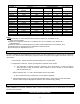
Cooling Water Requirements MODEL # D-400-W D-500-W D-600-W D-800-W D-1000-W D-1600-W D-2000-W D-2500-W D-3200-W D-4000-W D-5000-W D-6250-W D-7500-W D-8000-W D-10000-W HEAT TO COOLING AMBIENT (1) WATER 23682 1780 33894 2550 37250 3650 52859 3980 66150 5360 90845 7366 128646 10431 135330 10185 186550 14040 206480 15540 268075 20175 367117 27632 472231 35544 412960 31080 536150 40350 COOLING WATER GPM (2) GPM (3) 4.7 6.8 7.5 10.6 13.2 18 26 27 37 41 54 73.4 78.0 82.0 108 KW INPUT (4) 1.9 2.7 3.0 4.3 5.3 7.
SYMPTOMS PROBABLE CAUSE REMEDY Dryer not running. High temperature light off, analyzer gauge normal. a. Disconnect open. a. Close disconnect. b. Fuse blown. b. Replace fuse. c. Wiring, improper or broken. c. Check wiring diagram or repair. d. Control transformer defective. d. Replace. e. Unit not turned on. a. Overload tripped. e. Turn unit on. a. Allow to cool and reset. Check for overload. b. High pressure switch open (if supplied). b. Reset and check for cause. c.
SYMPTOMS Dryer running. High temperature light on, analyzer gauge pressure low. Dryer running. High temperature light off, analyzer gauge pressure low. Dryer not running. High temperature light on, analyzer gauge pressure low. Water downstream of the dryer. PROBABLE CAUSE REMEDY g. Defective refrigerant compressor valves. g. Repair or replace compressor. h. Suction pressure too high. h. Adjust hot gas bypass valve. a. Leaky refrigerant circuitry. a. Locate and repair. b.
High pressure drop across dryer inlet and outlet. Power light “ON” but dryer not running a. Excess flow. a. Dryer undersized. Replace with larger dryer. b. Low air pressure. b. Dryer undersized. Replace with larger dryer. c. Partially frozen. c. Shut dryer off until ice melts. a. No cooling water supply to dryer. a. Check cooling water supply. Reset refrigerant Hi/Lo pressure switch if interrupted.