AT&T DEFINITY 555-230-500 Issue 1, January 1992 ® Communications System Generic 1 & Generic 3 System Management
Copyright © 1991 AT&T All Rights Reserved Printed in U.S.A Notice While reasonable efforts were made to ensure that the information in this document was complete and accurate at the time of printing, AT&T can assume no responsibility for any errors. Changes and corrections to the information contained in this document may be incorporated into future reissues. Your Responsibility for Your System’s Security You are responsible for the security of your system.
Contents CHAPTER 1. INTRODUCTION ................................................................................................................. 1-1 Overview ...................................................................................................................................... 1-1 System Management ........................................................................................................................... 1-1 Initialization 1-2 ........................................
How to Administer Dial Plan and Feature Access Codes ................................................................ 4-8 How to Set Date and Time ....................................................................................................................... 4-10 How to Print on Demand ......................................................................................................................... 4-13 How to List History ................................................................
CHAPTER 9. REFERENCES ...................... ..................................................................... 9-1 CHAPTER 10. ABBREVIATIONS AND ACRONYMS ....................................................... 10-1 GLOSSARY .................................................................................................................. G-1 INDEX ..................................................................................................................................
Figures Figure 2-1. 715 MT Keyboard .................................................................................. Figure 2-2. 513 BCT Keyboard Function Keys and Programmable Keys . . . . . . . . . . . . . . . . . . . . . . . . . . . 2-10 Figure 2-3. Screen Labels Displayed When the LCL MENU Key is Pressed on a 513 BCT .... 2-12 Figure 2-4. Screen Display When the USER PF SET-UP Key is Pressed on a 513 BCT ......... 2-13 Figure 2-5.
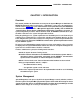
CHAPTER 1. INTRODUCTION CHAPTER 1. INTRODUCTION Overview This manual provides the information necessary for the System Manager to administer the DEFINITY® Communications System Generic 1 and Generic 3 using any of the administration terminals listed in Chapter 2.
CHAPTER 1. lNTRODUCTION System Manager's Role The System Manager is responsible for the following: ● Adding, changing, removing, and monitoring the system and voice terminal features on a day-to-day basis ● Performing system backup procedures ● Monitoring system performance ● Maintaining system security - Initialization After the system is installed and initialized, the System Manager can administer the system using the system administration terminal.
CHAPTER 1. lNTRODUCTlON When to Use This Manual This manual, along with the Implementation manual, provides the necessary guidelines to administer the system. The Implementation manual, when completed, contains the filled-out forms that reflect how your company wants to implement the system and voice terminal features. The information on these forms will be electronically entered in the system. The Implementation manual provides all the details for gathering translation data.
CHAPTER 1. INTRODUCTION ● ● Chapter 9. References provides a list of references for related documents. Chapter 10. Abbreviations and Acronyms lists abbreviations and acronyms for terms used in the DEFINlTY Communications System documentation. ● Glossary defines terms used in the DEFINITY Communications System documentation.
CHAPTER 2. DEFINITY ADMINISTRATION TERMINALS CHAPTER 2. DEFINITY ADMINISTRATION TERMINALS Overview The terminal used to administer a DEFINITY Communications System is identified in this document as the system administration terminal or the terminal. The terminal supplied with the system must be located within 50 feet of the system cabinet. The terminal consists of a video display and a keyboard that allow a System Manager to communicate with the system.
CHAPTER 2.
CHAPTER 2. DEFINITY ADMINISTRATION TERMINALS 715 MT Terminal The 715 MT terminal emulates the AT&T 615 MT Terminal/System 75 Cartridge combination (513 emulation) when operated in the “BCS” operating mode. The terminal operating mode is set by selecting the Emulation option of the User Preferences submenu or via an escape sequence. Keyboard Overview The 715 keyboard is equipped with special keys that allow the user to make corrections and do editing functions.
CHAPTER 2. DEFINITY ADMINISTRATION TERMINALS 513 BCT Keyboard The 513 BCT keyboard is equipped with special cursor keys that allow the user to make corrections and perform editing functions. Function keys that allow single keystrokes to do specific functions are also provided. Each type of key used on the 513 BCT is described in the following paragraphs. See Table 2-A for a list of the cursor keys, function keys, and programmable keys and a brief description.
CHAPTER 2. DEFINITY ADMINISTRATION TERMINALS TABLE 2-A. Terminal Keys For This Function 715‡ Terminal Type 513 4410 or or 610* 610† or or 615 MT* 615 MT† Press Key Below: 4425 Cancel CANCL [F1] [F1] To clear and redraw a screen form The system redraws the same screen. For the 4410 or 4425, the associated [F2] screen label (REFRESH) is displayed when the add, change, or display command is entered and the screen form is displayed.
CHAPTER 2. DEFINITY ADMINISTRATION TERMINALS TABLE 2-A (continued). Terminal Keys For This Function 715‡ Terminal Type 513 4410 or or 610* 610† or or 615 MT* 615 MT† Press Key Below: To display the next page of a screen form Used to display the next page of a screen form that has more than one page. For the 4410 or 4425, the associated [F7] screen label (NEXT PAGE) appears when the screen form has more than one page.
CHAPTER 2. DEFINITY ADMINISTRATION TERMINALS TABLE 2-A (continued) Terminal Keys Terminal Type 513 4410 or or 610† 610* For This Function 4425 715‡ 615 MT* 615 MT† Press Key Below: To display help information for a field or command Used to display help information on the type of data that can be entered into the field associated with the current cursor position. The system delays all the possible entries the user can input for that field.
CHAPTER 2. DEFINITY ADMINISTRATION TERMINALS TABLE 2-A (continued). Terminal Keys For This Function 715‡ To move the cursor to the previous field on a line If the cursor is in the first field on a line, then it moves to the last field of the previous line. If it is in the first field of the first line, then it moves to the last field of the last line.
CHAPTER 2. DEFINITY ADMINISTRATION TERMINALS TABLE 2-A (continued). Terminal Keys For This Function 715‡ To update the BCMS screen form using Monitor commands (G1) Used to obtain immediate update of real time status reports for agents and splits. Used only with the BCMS monitor bcms split and monitor bcms system commands.
CHAPTER 2. DEFINITY ADMINISTRATION TERMINALS NUMERIC LEGENDS ARE LOCATED ON THE FRONT SURFACES OF THE MATRIX AT THE BOTTOM OF THE RIGHT CLUSTER. FIGURE 2-2.
CHAPTER 2. DEFINITY ADMINISTRATION TERMINALS How to Program the Function Keys for a 513 BCT This section covers the procedures used to program the function keys for a 513 BCT. The programmable function keys can be used to save time by eliminating unnecessary typing. For example, a function key can be programmed to type the change station command. When the programmed key is pressed, change station appears on the terminal screen. The user then enters the extension number associated with the voice terminal.
CHAPTER 2. DEFINITY ADMINISTRATION TERMINALS F1 F2 F3 F4 F5 F6 F7 F8 FIGURE 2-3.
CHAPTER 2. DEFINITY ADMINISTRATION TERMINALS USER PF KEY SET-UP Label Action Function String f1: keyed f1 Oc f2: keyed f2 Od f3: keyed f3 Oe f4: keyed f4 Of f5: keyed f5 Og f6: keyed f6 Oh f7: keyed f 7 Oi f8: keyed f8 Oj F1 F2 F3 F4 F5 F6 F7 F8 FIGURE 2-4.
CHAPTER 2. DEFINITY ADMINISTRATION TERMINALS USER PF KEY SET-UP Label Action Function String DUPLICAT STATION duplicate station Hc f1: send f2: send f3: send f4: keyed f4 Of f5: keyed f5 Og f6: keyed f6 Oh f7: keyed f7 Oi f8: keyed f8 Oj F1 DISPLAY STATION CHANGE STATION F2 F3 display station Hc change station Hc F4 F5 F6 F7 F8 FIGURE 2-5.
CHAPTER 2. DEFINITY ADMINISTRATION TERMINALS 4425, 4410, 610, and 615 MT Terminals The 4425, 4410, 615 MT, and 610 terminals can also be used to administer DEFINITY Communication Systems. The 4425, 4410, 615 MT, and 610 terminals have eight function keys ([F1] through [F8]) that are automatically assigned functions by the system software. These keys allow the user to edit and fill out the screen forms and then submit the forms into system translations.
CHAPTER 2. DEFINITY ADMINISTRATION TERMINALS FIGURE 2-6.
CHAPTER 2. DEFINITY ADMINISTRATION TERMINALS FIGURE 2-7.
CHAPTER 2. DEFINITY ADMINISTRATION TERMINALS FIGURE 2-8.
CHAPTER 2. DEFINITY ADMINISTRATION TERMINALS FIGURE 2-9.
CHAPTER 3. SYSTEM ADMINISTRATION CHAPTER 3. SYSTEM ADMINISTRATION Administration Sequence After the system is installed, the System Manager must enter the translation data into the system memory using the system administration terminal. Before initializing the system, verify that the screen displays Login: If your terminal does not display Login:, call your AT&T Account Team. The Implementation manual for your DEFINlTY system provides the details for gathering the translation data.
CHAPTER 3. SYSTEM ADMINISTRATION These items cannot be added to the system; however, they can be changed to suit business needs by entering the change command for that feature and changing the screen form. The add command must be used to add trunks, pickup groups, hunt groups, and intercom groups. The duplicate command can be used to duplicate voice terminals and data modules.
CHAPTER 3. SYSTEM ADMINISTRATION System Parameters System parameters allow the System Manager to assign values for system related features such as Leave Word Calling (LWC), Hospitality Features, and Station Message Detail Recording (SMDR). Voice Terminals Once the Dial Plan and FACs have been assigned, the System Manager can add the various voice terminals. The duplicate command can be used to add the same types of voice terminals.
CHAPTER 3. SYSTEM ADMINISTRATION Groups After the voice terminals are added, the following items can be administered using the add com- mands: ● Abbreviated Dialing (System, Group, Enhanced) ● Hunt Groups ● Call Coverage Answer Groups ● Pickup Groups ● Intercom Groups ● Terminating Extension Groups Trunk Groups Trunk groups are assigned by entering the command add trunk group 1-99 (or next). For the Hospitality Reduction Parameter feature, only 50 trunk groups can be assigned.
CHAPTER 4. ADMINISTRATIVE TASKS-SYSTEM CHAPTER 4. ADMINISTRATIVE TASKS-SYSTEM This chapter covers administrative tasks that allow the System Manager to change system features to meet business requirements.
CHAPTER 4. ADMINISTRATIVE TASKS-SYSTEM System Login Procedures Note: If your DEFINlTY system is being used with a G3-MA, refer to DEFINITY ® Communications System Generic 3 Management Applications—Operations, 585-229202, for login procedures. The following procedure is used for logging into the system. 1. Turn on the terminal, if required. Screen displays: . Login: 2. Enter your login name and press [RETURN]. Screen displays: Password: 3. Enter your password and press [RETURN].
CHAPTER 4. ADMINISTRATIVE TASKS-SYSTEM 7. If enter command: is displayed, you can enter the desired command. Press [HELP] to obtain the list of permissible commands. System Logoff Procedure The system logoff procedure should be performed any time the system terminal is not being used. This assures the system translations will not be accidentally corrupted. To log off the system, type logoff and press [RETURN]. The system automatically disconnects you from the system.
CHAPTER 4. ADMINISTRATIVE TASKS-SYSTEM Note: Valid passwords contain four to seven alphabetic or numeric characters, or a combination of alpha and numeric characters. 8. Cursor is positioned on New Password (enter again): 9. Re-enter your new password. 10. Press [ENTER]. 11.
CHAPTER 4. ADMINISTRATIVE TASKS-SYSTEM Note: Remote Access users should be careful when using any command that requires user input such as next page. This command, if not used properly, will not let the system time out after 30 minutes and logoff the user. If the command is not used properly, system alarms cannot be reported which may affect system service. 1. If not translated previously, translate four Netcon channels. (See “How to Administer Netcon Channels” in this chapter.) 2.
CHAPTER 4. ADMINISTRATIVE TASKS-SYSTEM How to Administer the System From a Remote Location Make sure data terminal speed settings are set at 1200 bps. Top speed for a data or Netcon channel is 1200. 1. Using either the keyboard or a voice terminal, dial the UCD group extension number. This number will be one of the following: a. From off-premises: ● a DID number (seven or 10 digits) ● an LDN (seven or 10 digits) ● a trunk number dedicated to Remote Administration (seven or 10 digits) b.
CHAPTER 4. ADMINISTRATIVE TASKS-SYSTEM All four Netcon channels must be assigned. The following steps can be used to add a data or Netcon channel: 1. Verify that the terminal displays: enter command: 2. Enter add data module 4444 where 4444 is the extension number assigned to the Netcon channel. The extension number will appear in the Data Extension field on the screen form. Press [RETURN]. The screen displays a Processor Data Module (PDM) form. The cursor is positioned on the TYPE field. 3.
CHAPTER 4. ADMINISTRATIVE TASKS-SYSTEM How to Change a Netcon Channel Netcon channels can be changed by entering the command change data module 4444 and pressing [RETURN]. Extension number 4444 is the extension number assigned to the data or Netcon channel. Once the form is displayed on the screen, the user can make changes. Once all changes have been made, press [ENTER] to submit the changes into system translations.
CHAPTER 4. ADMINISTRATIVE TASKS-SYSTEM The following steps give an example of how to change a FAC from three to two digits. 1. Verify that the screen displays: enter command: 2. Enter change feature-access-codes and press [RETURN]. 3. The screen displays the FAC form. 4. Position the cursor over the 3-digit FAC and press the space bar until the 3-digit code disappears. 5. Press [RETURN] and repeat the above step until all 3-digit FACs have been removed. 6. Press [ENTER].
CHAPTER 4. ADMINISTRATE TASKS-SYSTEM How to Set Date and Time The system date and time are set using the Date and Time form (see Figure 4-2). This form is displayed on the terminal screen and is modified using the terminal keyboard. The time must be reset for daylight savings time. The correct time and date assure that SMDR records are correct for the records being kept. SMDR will not work until the date and time have been entered. Use the following procedure to set the system date and time: 1. Log in. 2.
CHAPTER 4. ADMINISTRATIVE TASKS-SYSTEM 8. Enter the current year (1990-2099) and press [RETURN]. Note: The cursor is positioned on Hour:. 9. Enter the current hour (0-23) and press [RETURN]. Table 4-A shows the standard time conversion to 24-hour time. Enter the 24-hour time as shown. For example, if the current time is 2:00 p.m., enter 14. Note: The cursor is positioned on Minute:. 10. Enter the current minute (0-59). 11. Press [ENTER]. 12.
CHAPTER 4. ADMINISTRATIVE TASKS-SYSTEM TABLE 4-A. Conversion to 24-Hour Clock 12-Hour Standard Time Clock 12:00 a.m. 1:00 a.m. 2:00 a.m. 3:00 a.m. 4:00 a.m. 5:00 a.m. 6:00 a.m. 7:00 a.m. 8:00 a.m. 9:00 a.m. 10:00 a.m. 11:00 a.m. 12:00 p.m. 1:00 p.m. 2:00 p.m. 3:00 p.m. 4:00 p.m. 5:00 p.m. 6:00 p.m. 7:00 p.m. 8:00 p.m. 9:00 p.m. 10:00 p.m. 11:00 p.m.
CHAPTER 4. ADMINISTRATIVE TASKS-SYSTEM How to Print on Demand The user can get a printout when print or the abbreviated version pr, is entered as the last qualifier for the list and display commands. For example, entering display abbreviated-dialing group 20 print provides a printout for AD group number 20. The terminal must have a printer connected to it before a hard copy printout can be obtained. The following procedure can be used to obtain a printout of Pickup Group 25. 1. Log on. 2.
CHAPTER 4. ADMINISTRATIVE TASKS-SYSTEM Figure 4-3 is an example of a typical list history command as displayed on the terminal. The command results are displayed in last-in first-out order. The date that translations were last saved on tape is printed followed by information under columns as follows: ● Date: Day and month that the command was issued. ● Time: Hour and minute that the command was issued. ● Port: A 3- or 4-character identifier that shows which port or ports the user was connected to.
CHAPTER 5. ADMINISTRATIVE TASKS-VOICE TERMINAL CHAPTER 5. ADMINISTRATIVE TASKS—VOICE TERMINAL How to Administer Voice Terminals Voice terminal administration is an integrated set of procedures that allow the user to add, change, remove, duplicate, display, and list the translation data associated with voice terminals. The voice terminal must be installed, connected, and initialized in system translations before the user can make a call.
CHAPTER 5. ADMINISTRATIVE TASKS-VOICE TERMINAL Before a voice terminal can be removed from the system, it must be removed from the following: ● Code Calling List ● Leave Word Calling (LWC) System Retrievers List ● Hunt Groups Assigned to the Call Management System (CMS) Translation data change may also be prevented when any affected feature is currently active; for example, a voice terminal cannot be removed while the message waiting indicator is on.
CHAPTER 5. ADMINISTRATIVE TASKS-VOICE TERMINAL ● ● ● ● ● ● 7303S, 7305S, or 7309H Voice Terminals: Up to eight voice terminals can be assigned to one TN762 Hybrid Line circuit pack. 7302H01B, 7303H01B, 7305H01B, or 7305H02B Voice Terminals: Up to eight voice terminals can be assigned to one TN762 Hybrid Line circuit pack. ISDN 7505, 7508, or 7507 Voice Terminals: In a multipoint configuration, up to 24 voice terminals can be assigned to the ISDN-BRI circuit pack TN556.
CHAPTER 5. ADMINISTRATIVE TASK-VOICE TERMINAL The 7302H01B and the 7303H01B are assigned using the 7303S Voice Terminal form. The 7305H01B and 7305H02B are assigned using the 7305S Voice Terminal form. Change Information on a Voice Terminal The change command allows you to change translations on an existing voice terminal. ● To change information on a voice terminal, enter change station 3600. The system displays the screen form that contains all the information currently assigned to extension 3600.
CHAPTER 5. ADMINISTRATIVE TASKS-VOICE TERMINAL Display Information on a Voice Terminal The display command allows you to look at a Voice Terminal form in the system. You cannot change, add, or delete anything on the displayed form. If you see something that should be changed, you must enter a change command such as change station 3600. ● To look at the features assigned to extension 3600, enter display stat ion 3600. The Voice Terminal form for extension 3600 is displayed on the screen.
CHAPTER 5. ADMINISTRATIVE TASKS-VOICE TERMINAL STATION Ext Port Name Security Code Room Jack Cable FIGURE 5-1. Duplication Station Form Without a Data Module STATION Ext Port Name Security Code Room Jack Cable Data Ext FIGURE 5-2.
CHAPTER 5. ADMINISTRATIVE TASKS-VOICE TERMINAL The following steps give a brief example of how to duplicate two 7403D voice terminals. 1. Enter duplication station 4000 [start extension 4001] [board] [count 2] and press [RETURN]. The screen displays the Station Duplication form and the two duplicated Voice Terminal screen forms. 2. Enter information on the appropriate the Station Duplication screen form. 3. Change information on the Voice Terminal screen form if required. 4. Press [ENTER].
CHAPTER 5. ADMINISTRATIVE TASKS-VOICE TERMINAL How to Administer Voice Terminals Without Hardware Administration Without Hardware (AWOH) provides the ability to administer station forms without specifying a port location. Stations administered as such will not cause alarm or errors to be generated when the station is translated but not yet installed. These station types are referred to as “phantom” stations.
CHAPTER 5.
CHAPTER 5. ADMINISTRATIVE TASKS-VOICE TERMINAL For the 7500B Data Module, multipoint administration is allowed for terminals with Service Profile Identification (SPID) initialization capabilities. if the duplicate data-module command is used to add a 7500B and the user wishes to add an SPID value which is different from the extension, the SPID field must be modified after the Data Extension field is entered or modified. The following commands can be used: ● add data-module xxxx (ext.
CHAPTER 6. HARDWARE RECONFIGURATION CHAPTER 6. HARDWARE RECONFIGURATION Overview Before voice terminals, trunks, and data modules can be added to the system, specific types of circuit pack must already be installed in the cabinet. The System Manager must determine if the required circuit pack exists in the system, and if a port on the circuit pack is vacant. If a vacant port is not available, a circuit pack must be installed before the corresponding voice terminal or trunk can be added.
CHAPTER 6. HARDWARE RECONFIGURATION Circuit Pack Administration Circuit pack administration is a capability that allows theSystem Manager to assign circuit packs to carrier slots before the circuit packs are actually installed in the slots. The circuit packs are assigned on the Circuit Pack screen form. The form has five pages, one for each of the port carriers. Page 1 is for Carrier A, page 2 is for Carrier B, etc. Before any voice terminals, attendant consoles, trunks, pooled modems, etc.
CHAPTER 7. SYSTEM BACKUP FOR DEFINITY G1 AND G3i CHAPTER 7. SYSTEM BACKUP FOR DEFINITY G1 AND G3i DEFINlTY G1 and G3i systems use a tape-only backup system with or without a duplication option. In case of a power failure of ten minutes or more, the system translations can be restored using the data on the system or backup tape.
CHAPTER 7. SYSTEM BACKUP FOR DEFINITY G1 AND G3i Tape Backup for a System Without the Duplication Option Two cassette tapes are provided with the system. It is recommended that backup copies of the translation data be made weekly, or after many changes have been made to the translation data. This will minimize the loss of recent translation data changes if the cassette tapes in the system become damaged. The following procedure can be used to make a backup tape: 1.
CHAPTER 7. SYSTEM BACKUP FOR DEFINITY G1 AND G3i 9. The screen displays: save announcement SPE A SAVE ANNOUNCEMENT Processor Command Completion Status SPE_A Error Code Success 0 Command successfully completely enter command: FIGURE 7-2. Save Announcements Screen—SPEA 10. Verify that a 0 is displayed for SPE_A in the Error Code column. A 0 indicates that the save announcement was a success for the tape drive. If a 0 did not appear, the save announcement did not complete.
CHAPTER 7. SYSTEM BACKUP FOR DEFINITY G1 AND G3i Tape Backup for a System With the Duplication Option Four cassette tapes are provided with the system. It is recommended that backup copies of the translation data be made weekly, or after many changes have been made to the translation data. This will minimize the loss of recent translation data changes if the cassette tapes in the system become damaged. The following procedure can be used to make backup tapes: 1.
CHAPTER 7. SYSTEM BACKUP FOR DEFINITY G1 AND G3i 9. The screen displays: save announcements SPE B SAVE ANNOUNCEMENT Processor SPE_B SPE_A Command Completion Status Success Success Error Code 0 0 Command successfully completely enter command: FIGURE 7-4. Save Announcements—SPE_B Administration Note: The active SPE’s completion status is always displayed first.
CHAPTER 7. SYSTEM BACKUP FOR DEFINITY G1 AND G3i Tape Errors Since the tape drive is a mechanical device, tape-related failures may occur. When these failures occur, the system responds with “tape error messages”. The following is a list of the tape error messages and recommended responses to each. Check for proper operation after each response is done. 1. Tape access error: no tape cartridge or device problem Indicates that the cassette tape is missing or improperly seated.
CHAPTER 7. SYSTEM BACKUP FOR DEFINITY G1 AND G3i 6. Internal translation data is corrupted Indicates that the translation data is inconsistent and the translation was not saved on tape. Response: Replace cassette tape with system backup tape. Enter the command reset system 3. After the command completes, remove the backup tape, install the original tape, and then repeat the command that generated the error message. Notify maintenance support if the same error message is displayed again. 7.
CHAPTER 8. SYSTEM BACKUP FOR DEFINITY G3r CHAPTER 8. SYSTEM BACKUP FOR DEFINITY G3r Overview The DEFINITY G3r Mass Storage System (MSS) utilizes tape and disk to provide stable storage of switch data. MSS configurations include single Switch Processing Element (SPE) and dupli- cated systems. There are four basic MSS configurations: Simplex Tape-Only In a simplex tape-only system, the tape drive is the primary MSS device.
CHAPTER 8. SYSTEM BACKUP FOR DEFINITY G3r Command Interface Conventions In the following sections, the commands used to interface with the MSS are described. The conventions used to describe the commands are: Optional Command Arguments A set of brackets [ ] is used to designate optional groups of arguments to a command. One item listed within each set of brackets can be specified on the command line.
CHAPTER 8. SYSTEM BACKUP FOR DEFINITY G3r Invoking the save announcements command with the either option forces the system to write the announcements data to the specified device in both mass storage systems concurrently. If there is a failure in accessing one of the devices, the announcements data will still be written to the device that has not failed. The [disk | tape] options specify the device on which to save the announcements data. These options only apply in a system with a disk.
CHAPTER 8. SYSTEM BACKUP FOR DEFINITY G3r If the user requests that announcements be saved to a tape, the tape must be in service (E14). If the user requests that announcements be saved to the standby processor, the standby processor must be in service and shadowing must be enabled (E16). If an error is encountered in the above steps, the save operation is not attempted.
CHAPTER 8. SYSTEM BACKUP FOR DEFINITY G3r If a good copy of the announcement file is not available, then the restore announcements operation cannot be executed until the save announcements command is successfully completed. The announcements on the board are still accessible and usable. Restore Announcements Command The restore announcements command copies announcement data from the specified MSS device to the announcement board (TN750).
CHAPTER 8. SYSTEM BACKUP FOR DEFINITY G3r If restoring from tape, the restore announcements command will abort if no tape is in the tape drive (E37). The restore announcements command will also abort if: ● No system access port is available (E39). ● The MSS is in use by the SPE duplication memory refresh activity (E41). Announcements on the ANN board will not be available until the restore operation is complete. Treatment to calling users will vary according to the feature.
CHAPTER 8. SYSTEM BACKUP FOR DEFINITY G3r Error Conditions The following is a list of all error messages displayed to the user. If any of these error conditions can be attributed to hardware failures or disk/tape configuration problems, they will be logged with the maintenance subsystem. Error messages that are caused by a user entering improper command operations will not be logged with the maintenance subsystem; the user is notified of the error.
CHAPTER 8. SYSTEM BACKUP FOR DEFINITY G3r E31 (W) Announcement port in use; please try later. One or more of the announcement ports are in use. The port could be in use for an integrated announcements session or for integrated announcement playback. E32 (W) Bad announcement file on tape (disk). This message indicates that the announcement file stored on disk or tape is corrupt. A valid file must be stored on the MSS before it can be accessed.
CHAPTER 8. SYSTEM BACKUP FOR DEFINITY G3r Save Translation Command The save translation command copies translation data from memory to the MSS. By default, translation data is written to the primary MSS device in a simplex processor system, or to both primary MSS devices in a duplicated processor system. In addition, the save translation command can be directed to write to devices on either of the processors and/or the secondary device(s).
CHAPTER 8. SYSTEM BACKUP FOR DEFINITY G3r Command Operation The save translation command writes two time-stamped identical copies of translation data to the selected device(s). The time stamp for both copies will be the same (it will be the time of writing to the first copy). Each copy is written as consecutive 2K blocks. Each block contains a checksum for error detection purposes. Each copy contains a time stamp and the state of the copy (either “good” or “bad”).
CHAPTER 8. SYSTEM BACKUP FOR DEFINITY G3r The command completion status is displayed on the screen, as shown below. Save Translation Processor Command Completion Status SPE_A* SPE_B* success/specific error message success/specific error message Error Code nl n2 * In a simplex system, only the active (default) SPE status is given. ln a duplex system if a qualifier is used to select save translation for only one SPE, only that SPE’s status is given. FIGURE 8-1.
CHAPTER 8. SYSTEM BACKUP FOR DEFINITY G3r The following operational rules apply to the save translation command: 1. The save translation command will only be allowed if there are no translation updates being made. All requests to update translation, after the command starts, will be denied (E1). If Terminal Translation Initialization (TTI) activation or deactivation is in progress, the save translation command will be denied (E2). 2.
CHAPTER 8. SYSTEM BACKUP FOR DEFINITY G3r Backup Command Additional data integrity is achievable through disk to tape backups. These backups may be done on demand or run daily as part of scheduled maintenance. This command is only valid in a system which has both disk and tape as part of its MSS. The backup command will work in either a simplex SPE or a duplex SPE system. When the command is run as part of scheduled maintenance, the default for a simplex system is an incremental backup of SPE A.
CHAPTER 8. SYSTEM BACKUP FOR DEFINITY G3r Command Operation When an incremental backup is performed, the following procedure governs this operation. Before each file is copied from the disk to the tape, the file on the tape is marked as “bad.” When the file has been completely copied over to the tape, the file is then marked as “good” on the tape.
CHAPTER 8. SYSTEM BACKUP FOR DEFINITY G3r 4. If the user requests that the backup take place on the standby processor, the standby processor must be in service, shadowing enabled, and refresh completed (E16). If the file system of the tape is a core-dump file system, the command will be denied (E17).
CHAPTER 8. SYSTEM BACKUP FOR DEFINITY G3r Invoking the restore command with the standby option causes files from the tape associated with the standby processor to be copied to the disk on that same processor. Invoking the restore command with the both option forces the system to copy files from the tape-to-disk device on both mass storage systems concurrently. If the standby processor is inaccessible, the command will fail on both processors.
CHAPTER 8. SYSTEM BACKUP FOR DEFINITY G3r The following operational rules apply to the restore command: 1. The restore command will only be allowed to run if there are no other applications currently using the MSS devices (E3). 2. The options entered by the user will be validated against the system configuration, and the target devices for the restore command are determined (E11). 3. The disk must be in service (E13). The tape must be in service (E14). 4.
CHAPTER 8. SYSTEM BACKUP FOR DEFINITY G3r E5 (W) Tape write failure: tape cartridge or device failure This message means that there is a failure in writing to the tape. This maybe caused by the tape cartridge missing from the tape drive, or by non-operational tape hardware. E6 (W) Tape read failure: tape cartridge or device failure This message means there is a failure in reading from the tape. This maybe caused by the tape cartridge missing from the tape drive, or by non-operational tape hardware.
CHAPTER 8. SYSTEM BACKUP FOR DEFINITY G3r E19 (W) Large system boot image is corrupt on the tape This message means that the large system boot image has been overwritten by a core dump. The tape cannot be converted to a large system tape. E22 (W) Tape file contains an installation file system This message indicates that the wrong type of tape is in the tape drive.
CHAPTER 9. REFERENCES CHAPTER 9. REFERENCES The following is an abbreviated listing of Generic 1 and Generic 3 documents. Included is a brief description of each document in the list. User instructions are also available for all terminals used with the systems. To order copies of any of these documents, refer to the address on the back of the title page. 555-000-010 Business Communications Systems Publications Catalog Provides a list of publications that support AT&T business communications systems.
CHAPTER 9. REFERENCES DEFINITY® Communications System Voice Terminal DocuMaster Kit 555-230-750 A multi-element kit for end users to provide them with the information they need to use their voice terminals. The kit includes: ● ● A “how-to-use” booklet with procedural instructions plus sample applications PC Phone Facts, an enhanced version of the Feature Facts programs available for other phone systems. This is a PC-based program compatible with MS-DOS® personal computers.
CHAPTER 9. REFERENCES DEFINITY® Communications System Generic 1 and Generic 3i—System 555-204-510 Reports Explains switch-based measurement, traffic, performance, and summary reports. Descriptions include the overall purpose and uses for each report, complete definitions for each field, correlations with other reports, and possible actions that can be taken to further diagnose situations and remedy unsatisfactory conditions.
CHAPTER 9. REFERENCES DEFINITY® Communication System Generic 3 Call Vectoring Guide 535-230-520 Discusses how to write, use, and troubleshoot vectors, which are command sequences that process telephone calls in an Automatic Call Distribution (ACD) environment.
CHAPTER 10. ABBREVIATI0NS AND ACRONYMS CHAPTER 10.
CHAPTER 10.
CHAPTER 10.
CHAPTER 10.
CHAPTER 10.
GLOSSARY GLOSSARY A Access Code A 1-, 2-, or 3-digit dial code used to activate or cancel a feature or access an outgoing trunk. The star (*) and pound (#) can be used as the first digit of an access code. Access Endpoint Either a non-signaling channel on a DS1 interface or a non-signaling port on an Analog Tie Trunk circuit pack that is assigned a unique extension. Access Tie Trunks Tie trunks used to handle normal ETN calls between main and tandem switches.
GLOSSARY Announcements Announcements are prerecorded messages that give the caller information. If the first announcement given to a caller is played before the call is queued to any split, it is a Forced First Announcement. Answer-Back Code A code dialed to retrieve a parked call. Answer Supervision Answer supervision is a signal, sent from the switch to the serving CO, that tells the CO to begin recording toll charges for a call.
GLOSSARY Asynchronous Data Unit (ADU) A data communications equipment (DCE)-type device that allows direct connection between EIA-232-C equipment and the system digital switch. Attendant The operator of the attendant console. Individual who handles the processing of various types of internal, incoming, and outgoing calls. May also manage and monitor some of the system’s operations. Attendant Console An electronic call-handling position with pushbutton control.
GLOSSARY Automatic Route Selection Automatic Route Selection provides automatic routing of outgoing calls over customer trunk facilities with transparent access to an Inter-Exchange Carrier (IXC) based on the Direct Distance Dialing (DDD) number. Alternate trunk groups are selected during peak demand periods when the primary trunk groups are busy. The alternate trunk groups are selected in decreasing order of preference for making the calls.
GLOSSARY Bearer Capability Class (BCC) The Bearer Capability Class (BCC) identifies the type of a call, for example, voice and different types of data. Determination of BCC is based on the call originator’s characteristics for non-ISDN endpoints and on signaling in the D-channel for ISDN endpoints. There are five Bearer Capability Classes (0-4), based on voice and data Modes 0, 1, 2, 3 capabilities.
GLOSSARY C Call Appearance, Attendant Console Six buttons, labeled a through f, used to originate, receive, and hold calls. Each button has two associated lamps to show the status of the call appearance. Call Appearance, Voice Terminal A button labeled with an extension number used to place outgoing calls, receive incoming calls, or hold calls. Two lamps next to the button show the status of the call appearance or status of the call.
GLOSSARY Call Work Code A number, up to 16 digits, entered by ACD agents to record the occurrence of customerdefined events (such as account codes, social security numbers, or phone numbers) on ACD calls. Central Office The location housing telephone switching equipment that provides local telephone service and access to toll facilities for long-distance calling. Central Office Codes The first three digits of a 7-digit public network telephone number.
GLOSSARY Console See Attendant Console. Controlled Outward Restriction A calling party with this feature activated is restricted from dialing outgoing exchange network calls. Restricted calls are routed to the attendant, coverage, or intercept. Controlled Restrictions The controlled restrictions are distinct from the calling and called restrictions administered through the COR. Controlled Restrictions are activated by an attendant or by a station with the “Console Permission” COS.
GLOSSARY Coverage Point The attendant positions (as a group), Direct Department Calling group, Uniform Call Distribution group, Coverage Answer Group, a voice terminal extension, or Message Center Hunt Group designated as an alternate answering position in a coverage path. Covering User The person at an alternate answering position who answers a coverage call. D Data Channel A communications path between two points used to transmit digital signals.
GLOSSARY Designated Voice Terminal The specific voice terminal to which calls, originally directed to a certain extension number, are redirected. Commonly used to mean the “forwarded-to” terminal when Call Forwarding All Calls is active. Dialed Number Identification Service Provides an indication (display) to the answering agent of the service (or project) or number called by the caller so that agents grouped in one split may answer calls appropriately for many different services.
GLOSSARY Digital Trunk A circuit in a telecommunications channel designed to handle digital voice and data. Digit Conversion A process used to convert specific dialed numbers into other dialed numbers. ARS uses Digit Conversion to convert public network numbers (ARS) to private network numbers (AAR) in order to save toll charges. AAR uses Digit Conversion to convert private network numbers (ARS) to other private or public network numbers (AAR).
GLOSSARY E Electronic Tandem Network (ETN) A special tandem tie trunk network that has automatic call routing capabilities based on the number dialed and most preferred route available at the time the call is placed. Each switch in the network is assigned a unique RNX and each voice terminal is assigned a unique extension number. End-to-End Signaling The transmission of touch-tone signals generated by dialing from a voice terminal user to remote computer equipment.
GLOSSARY F Facility A general term used for the telecommunications transmission pathway and associated equipment. Facility Restriction Level (FRL) The FRL is used to determine the accessibility of user trunk groups in a routing pattern. When searching for a routing pattern, the originator's FRL must be greater than or equal to the FRL for the accessed trunk group.
GLOSSARY G Ground-Start Trunk On outgoing calls, the system transmits a request for services to the distant switching system by grounding the trunk ring lead. When the distant system is ready to receive the digits of the called number, that system grounds the trunk tip lead. When the system detects this ground, the digits are sent. (Tip and ring are common nomenclature to differentiate between ground-start trunk leads.
GLOSSARY I Immediate-Start Tie Trunk After establishing a connection with the distant switching system for an outgoing call, the system waits a nominal 65 milliseconds before sending the digits of the called number. This allows time for the distant system to prepare to receive the digits. Similarly, on an incoming call, the system has less than 65 milliseconds to prepare to receive the digits.
GLOSSARY Interworking The linking of dissimilar networks to provide an end-to-end call. In public networks, interworking might include a Common Channel Interoffice Signaling (CCIS) path which does not support ISDN. In private networks, a tandeming PBX might interface an existing analog facility to an ISDN facility to provide calls end-to-end. Intraflow Intraflow allows calls that are unanswered within a predefined time, at a split to be redirected to other splits on the same switch.
GLOSSARY L Link A transmitter-receiver channel or system that connects two locations. Listed Directory Number A LDN is a publicly listed telephone number for an organization. These numbers are administered as special extensions, each associated with a 15-character name. DID for any of these extensions causes routing of the call to the attendant group with the terminating attendant display indicating an LDN call and the name associated with the dialed extension.
GLOSSARY Manual-In Manual-In is an ACD agent work mode that makes the agent available to receive calls and automatically puts the agent into After Call Work mode after disconnecting from an ACD call. Manual Terminating Line Service A called party that has manual terminating line service is only allowed to receive calls originated or extended by an attendant. Termination of all other calls is denied.
GLOSSARY Modem Pooling Provides shared-use conversion resources that eliminate the need for a dedicated modem when a data module accesses, or is accessed by, an analog line or trunk. Multi-Appearance Voice Terminal A terminal equipped with several call appearance buttons for the same extension number. Allows the user to handle more than one call, on that same extension number, at the same time. Multiplexer A device for simultaneous transmission of two or more signals over a common transmission medium.
GLOSSARY On-Net On-Net facilities (for example, TTI trunks, private ISDN-PRI trunks) are dedicated to a customer's private network. Whenever the call is routed over the customer's private trunking facilities, it is called an On-Net call.
GLOSSARY Primary/Secondary D-Channel The D-Channel Backup feature requires that one D-Channel be administered as the primary D-Channel, and that a second D-Channel be administered as the secondary DChannel. The reason for this distinction is that at certain times during the D-Channel Backup procedures, both D-Channels are in the same state, and it is imperative in order to avoid a deadlock situation that both switches at opposite ends of the PRI select the same D-Channel to be put into service.
GLOSSARY Property Management System (PMS) A stand-alone computer that lodging and health services organizations use for services such as reservations, housekeeping, billing, etc. Protocol A set of conventions or rules governing the format and timing of message exchanges to control data movement and correction of errors. Public Network The network that can be openly accessed by all customers for local or longdistance calling. Q Queue An ordered sequence of calls waiting to be processed.
GLOSSARY Remote Access Barrier Code Used with remote access trunks to limit access to the System. When a call comes in on a remote access trunk, the user may be required to dial a barrier code to gain access. If the user dials an invalid barrier code, the call is muted to intercept. A barrier code has an associated COR that defines call restriction features and a COS that defines feature restrictions. The use of barrier codes is a customer option.
GLOSSARY s Secondary Reference The secondary reference is a backup DS1 facility used as a clock timing reference for synchronization in case the primary reference fails or has too many slips. Service Observing Service observing allows users to monitor calls. Once the feature is activated and a station call is being monitored, the activating user has the capability to toggle back and forth between a listen-only connection and a listen/talk connection on the call.
GLOSSARY Stroke Counts Method used by ACD agents to record up to nine customer-defined events on a per call basis when the CMS is active. Suffix A suffix is an alphabetic character (for example, A, B, or C) that is sometimes appended to a circuit pack code (TN number). It indicates additional feature functionality of a particular circuit pack. Switchhook The button(s) on a voice terminal located under the receiver.
GLOSSARY Tandem Tie Trunk Network (TTTN) A private network that interconnects several customer switching systems by dialrepeating tie trunks. Access to the various systems is dictated by codes that must be individually dialed for each system. Terminal Alarm Notification A method of customer alarm notification using lamps associated with feature buttons on multi-appearance digital or hybrid voice terminals or attendant console terminals or both.
GLOSSARY Tone/Clock The Tone/Clock circuit pack provides tone generation and timing for the TDM bus. The active Tone/Clock circuit pack is currently providing service for the cabinet in a duplicated system whereas the standby tone/clock is a backup circuit pack in the event the active tone/clock fails. Tone Ringer A device with a speaker, used in electronic voice terminals to alert the user. Trunk A telecommunications channel between two switching systems.
GLOSSARY Vectoring (Basic) Allows the customer to specify the treatment of calls coming into the switch based upon the dialed number. Vectoring (Basic) allows incoming calls to be placed in a queue for a hunt group or split and may specify the delay treatment given to the caller. Vectoring (Prompting) Allows a call vector to collect digits from a user and use that information in routing the call. Voice Terminal A single-line or multi-appearance voice terminal (telephone).
INDEX INDEX 4410 Terminal, 2-1 Administration Keys, 2-15 Function Keys, 2-15 Keyboard, 2-1 4425 Terminal, 2-1 Administration Keys, 2-15 Function Keys, 2-15 Keyboard, 2-1 513 BCT, 2-1 Keyboard, 2-1, 2-4 Keyboard, Function Keys and Programmable Keys, 2-10 Programmable Function Keys, 2-11 610 BCT, 2-1 Administration Keys, 2-15 Function Keys, 2-15 Keyboard, 2-1 615 MT Terminal, 2-1 Administration Keys, 2-15 Function Keys, 2-15 Keyboard, 2-1 715 MT Terminal, 2-3 keyboard overview, 2-3 7400B Data Module, 5-9 Gr
INDEX B Backspace Key, 2-4 Backup, 7-1 for a System With Duplication Option, 7-4 for a System Without Duplication Option Tape, 7-2 Backup Disk, 8-1 Backup Disk/Tape, 8-1 Backup Recorded Announcements, 7-1 Backup System, 7-1, 8-1 Backup Tape for a System Without Duplication Option, 7-2 Business Communications Terminal 513, 2-1 513, Keyboard, 2-1 610, 2-1 610, Keyboard, 2-1 C Cancel Key, 2-1 Cassette Tapes, 7-2, 7-4 Errors, 7-6 Failures, 7-6 Change Date, 4-10 Day of Week, 4-10 Dial Plan Record, 4-8 Feature
INDEX Display Information Voice Terminal, 5-5 Translation Data Associated With Voice Terminal, 5-5 E Enhanced Terminal Administration, 5-1 Enter Key, 2-1 Error Conditions, 8-2, 8-17 Establish Dial Plan, 3-2 F Feature Access Codes, 3-2 Features Administration Without Hardware, 5-8 Find Extension Numbers Assigned to Netcon Channels, 4-8 How Many Netcon Channels Have Been Assigned, 4-8 Function Keys, 2-4 513 BCT, 2-4 Assignments, by System Software, 2-1 Assignments, for 4410, 2-1 Assignments, for 4425, 2-1
INDEX I Identify Groups to Which a Voice Terminal Belongs, 5-5 Incorrect Login, 4-2 Initialization, 1-2 Initialize System, 1-2 Introduction, 1-1 K Keeping Records, 1-2 Keyboard Overview 715 MT, 2-3 N Netcon Channels, 3-3, 4-5 Administration, 4-6 and SMDR, 4-6 Network Access Feature Forms, 3-4 Next Form Key, 2-1 Next Page Key, 2-1 O Ongoing Administration, 1-2 P L Label Backup Tapes for a System With Duplication Option, 7-4 for a System Without Duplication Option, 7-2 List Configuration Commands, 5-1 Net
INDEX R Record Keeping, 1-2 Recorded Announcements Backup, 7-1 command, 7-1 References, 9-1 Refresh Key, 2-1 Remote Administration, 44 Remove and Replace Tapes for System Backup, for a System With Duplication Option, 7-4 for System Backup, for a System Without Duplication Option, 7-2 Remove Feature Buttons From Voice Terminal, 5-4 Remove Features From Voice Terminal, 5-4 Remove Voice Terminal, 5-4 Reset Clock After System Recovery, 4-10 Reset Date, 4-10 Reset System Clock, 4-10 Reset Time, 4-10 Restore Ann
INDEX Terminal 615 MT Terminal, 2-1 Keyboard, 615 MT Terminal, 2-1 Keys Table, 2-5 Terminal Types, 2-1 Used for Administration, 2-1 Time and Date Screen Form, 4-10 Time Required to do a Backup on Recorded Announcements, 7-1 Transaction Log, 4-13 Trunk Configurations, 6-1 Trunk Data Module Administration, 5-9 Trunk Data Modules, 3-3 Trunk Groups, 3-4 Types of Administration Terminals, 2-1 I-6 v Voice Terminal, 3-3 Add, 5-3 Adjuncts Administer, 5-9 Administer, 5-1 Change, 5-4 commands, 5-3 Remove, 5-4 w W
AT&T 555-230-500ADD Issue 1, January 1992 Dated September 1992 DEFINITY ® Communications System Generic 1 and Generic 3 System Management Addendum
©1992 AT&T All Rights Reserved Printed in USA Notice While reasonable effort was made to ensure that the information in this document was complete and accurate at the time of printing, AT&T cannot assume responsibility for any errors. Changes and/or corrections to the information contained in this document may be incorporated into future issues. Your Responsibility for Your System’s Security You are responsible for the security of your system.
Contents INTRODUCTION ............................................................................................................. 1 Overview ............................................................................................................... 1 Organization .................................................................................................................... 2 SYSTEM BACKUP FOR DEFINITY G3s ............................................................................
Figures Figure 1-1. Save Translation—SPEA ................................................................................................ 1-2 Figure 1-2. Save Announcements Screen—SPEA ................................................................. 1-3 Figure 1-3. Memory Card Write-Protect Switch ..........................................................................
INTRODUCTION INTRODUCTION Overview This addendum provides specific information for performing a System Backup for a DEFINITY® Communications System Generic 3s (G3s) switch release. Its function is as a supplement to, and is intended to be used in conjunction with, the information already provided in DEFINITY Communications System Generic 1 and Genetic 3 System Management, 555-230-500, Issue 1.
INTRODUCTION Organization Note: In the interest of brevity, only G3s specific information is provided in this addendum. Refer to the appropriate section in DEFINITY Communications System Generic 1 and Generic 3 System Management, 555-230-500, Issue 1, when performing other administration tasks. This document consists of the following chapters: Introduction — Describes this document.
SYSTEM BACKUP FOR DEFINITY G3s SYSTEM BACKUP FOR DEFINITY G3s The backup system for the DEFINITY G3s system employs a Memory Card. It does not have a duplication option. In case of a power failure, the system translations and announcements can be restored using the Memory Card. Save Translation Translation data can be routinely saved every 24 hours. However, if your translation data changes frequently, you should also save translations frequently to assure that you have the most up-to-date information.
SYSTEM BACKUP FOR DEFINITY G3s The following procedure can be used to make a backup Memory Card: 1. Remove the Memory Card from the Netcon circuit pack. 2. Insert the backup Memory Card into the Netcon circuit pack. 3. Login to the administration terminal. 4. Verify that the screen displays: enter command: 5. Enter save translation and press [RETURN]. This command instructs the system to take all translation information in memory and transfer it into the Memory Card. 6.
SYSTEM BACKUP FOR DEFINITY G3S 9. The screen displays: save announcements SAVE ANNOUNCEMENTS Processor Command Completion Status Error Code Success SPE_A 0 Command successfully completely enter command: FIGURE 1-2. Save Announcements Screen—SPEA 10. Verify that the Success message appears in the Command Completion Status field. If it does not, an error message will appear instead. 11.
SYSTEM BACKUP FOR DEFINITY G3s Errors Memory Card-related failures may occur for two reasons: the card is at fault or the Netcon circuit pack is at fault. When these failures occur, the system responds with “error messages.” The following is a list of the error messages and recommended responses to each. Check for proper operation after each response is done. 1. Saved copy of announcements is unusable The file on the Memory Card is unusable. Response: Use another backup card if you have one.
SYSTEM BACKUP FOR DEFINITY G3s 9. Memory Card is not inserted in the system Response: Insert the Memory Card. 10. Cannot access file; wrong type of Memory Card is inserted You have not inserted the correct Memory Card for the operation you wish to perform. Load the appropriate Memory Card. 11. File size exceeded You have run out of file space. Response: Call your AT&T representative. 12. Upgrade Memory Card inserted You may have inserted the System Upgrade Memory Card instead of the 4 Mb Memory card.
SYSTEM BACKUP FOR DEFINITY G3S 15. Command has been aborted; please try later The command has been pre-empted. Response: Try again later. 16. Saved copy of translation is unusable The copy of the translations on your Memory Card is faulty. Response: Run the save translations command again. 17. Unknown type of Memory Card The software does not know what type of Memory Card is inserted in the slot.
Index Index M A Announcements restore, 1-1 Memory Card Failures, 14 Memory Cards, 1-1 Errors, 1-4 Failures, 14 P B Backup, 1-1 for a G3s System, 1-1 G3s System, 1-1 using Memory Cards, 1-1 Backup Memory Card(s) for a G3s System, 1-1 Backup Recorded Announcements, 1-1 Backup System, 1-1 C commands Used to Backup Recorded Announcements, 1-1 Used to Save Recorded Announcements, 1-1 E Error messages, 1-4 Errors, 1-4 H How to Backup Recorded Announcements, 1-1 How to Restore Announcements, 1-1 How to Save
Index T Time Required to do a Backup on Recorded Announcements, 1-1 I-2 W When to Save Recorded Announcements, 1-1
AT&T 555-230-500ADD2 Issue 1, January 1992 Dated March 1993 DEFINITY ® Communications System Generic 1 and Generic 3 System Management Addendum (G3vs Customers Only)
©1993 AT&T All Rights Reserved Printed in USA Notice While reasonable effort was made to ensure that the information in this document was complete and accurate at the time of printing, AT&T cannot assume responsibility for any errors. Changes and/or corrections to the information contained in this document maybe incorporated into future issues. Your Responsibility for Your System’s Security You are responsible for the security of your system.
Contents About this Document ■ ■ 1 Overview Organization Save Translation Save and Restore Recorded Announcements ■ Errors 1-1 1-1 1-5 1-6 Index I-1 SYSTEM BACKUP FOR DEFINITY G3VS ■ ■ I i i ii i
Screens 1 SYSTEM BACKUP FOR DEFINITY G3VS 1-1. 1-2. 1-3. 1-4.
About this Document Overview This addendum provides specific information for performing a System Backup for a DEFINITY® Communications System Generic 3vs (G3vs) switch release. Its function is as a supplement to, and is intended to be used in conjunction with, the information already provided in DEFINITY Communications System Generic 1 and Generic 3 System Management, 555-230-500, Issue 1.
About this Document Organization In the interest of brevity, only G3VS specific information is provided in this addendum. Refer to the appropriate section in DEFINITY Communications System Generic 1 and Generic 3 System Management, 555-230-500, Issue 1, when performing other administration tasks. This document consists of the following chapters: Introduction — Describes this document.
SYSTEM BACKUP FOR DEFINITY G3VS 1 The backup system for the DEFINITY G3VS system employs a Memory Card. The standard Memory Card is a 1 Mb card for systems without a TN750 announcement circuit pack. It does not have high or critical reliability. In case of a power failure, the system translations and announcements can be restored using the Memory Card. Save Translation Translation data can be automatically saved every 24 hours.
SYSTEM BACKUP FOR DEFINITY G3vs 4. Enter save translation and press [RETURN]. This command instructs the system to take all translation information in memory and transfer it into the Memory Card. 5. The screen displays: save translation SPE A SAVE TRANSLATION Processor Command Completion Status SPE_A Success Error Code 0 Command successfully completely enter command: Screen 1-1. Save Translation Screen—SPEA 6. Verify that the Success message appears in the Command Completion Status field.
SYSTEM BACKUP FOR DEFINITY G3vs One Memory Card is provided with the system. If a backup Memory Card has been purchased, the following procedure can be used to make a backup copy of the system translations and/or announcements. 1. Remove the Memory Card from the TN777B Netcon circuit pack. 2. Insert the backup Memory Card into the TN777B Netcon circuit pack. 3. Log in to the administration terminal. 4. Verify that the screen displays: enter command: 5. Enter save translation and press [RETURN].
SYSTEM BACKUP FOR DEFINITY G3vs 9. The screen displays: save announcements SAVE ANNOUNCEMENTS Processor Command Completion Status SPE_A Success Error Code 0 Command successfully completely enter command: Screen 1-4. Save Announcements Screen-SPEA 10. Verify that the Success message appears in the Command Completion Status field. If it does not, an error message will appear instead. 11.
SYSTEM BACKUP FOR DEFINITY G3vs Save and Restore Recorded Announcements Enter the save announcements command to save the recorded announcements in the system on the system Memory Cards. NOTE: A 4 Mb Memory Card is required to save and restore announcements. The system takes about 30 minutes to complete this task.
SYSTEM BACKUP FOR DEFINITY G3vs Errors Memory Card-related failures may occur for two reasons: the card is at fault or the (TN777B) Netcon circuit pack is at fault. When these failures occur, the system responds with “error messages.” The following is a list of the error messages in alphabetical order and recommended responses to each. Check for proper operation after each response is done.
SYSTEM BACKUP FOR DEFINITY G3vs 7. File size exceeded You have run out of file space. Response: Call your AT&T representative. 8. Invalid directory on memory card Indicates the Memory Card needs refreshing, or that something is wrong with the Memory Card. Response: Run test card-mem and be sure all tests pass. Replace the Memory Card. 9. Memory Card is not inserted in the system You have not inserted the memory card. Response: Insert the Memory Card. 10.
SYSTEM BACKUP FOR DEFINITY G3vs 12. Request is incompatible with currently running operations Indicates the storage system is in use. Response: Try again later. 13. Saved copy of announcements is unusable The file on the Memory Card is unusable. Response: Use another backup card if you have one. Instances such as this illustrate the importance of having backup cards. 14. Saved copy of translations is unusable The copy of the translations on your Memory Card is faulty.
SYSTEM BACKUP FOR DEFINITY G3vs 16. Unknown type of Memory Card The software does not know what type of Memory Card is inserted in the slot. This can occur if the card is unformatted or if the current vintage of the software does not recognize that type of Memory Card. Response: Replace the Memory Card with a formatted Memory Card the software can recognize. 17. Upgrade Memory Card inserted You may have inserted the System Upgrade Memory Card instead of the 4 Mb Memory Card.
Index A R Announcements restore, 1-5 Recorded Announcements Backup, 1-5 Command, 1-5 Restore Recorded Announcements, 1-5 B Backup, 1-1 G3VS System, 1-1 using Memory Cards, 1-1 Backup Recorded Announcements, 1-5 Backup System, 1-1 S Save Announcements, 1-5 Save Changes Additions, 1-1 Save Data in Memory, 1-1 C Commands Backup Recorded Announcements, 1-5 Save Recorded Announcements, 1-5 Save Information in Memory, 1-1 Save Recorded Announcements, 1-5 Command, 1-5 Save Translation, 1-1 Automatically,