The 8400-Series Voice Terminals Installation and User’s Manual (includes instructions for the 8403, 8405, 8410, 8411, and 8434DX voice terminals)
DO NOT DISCARD THE BLANK DESIGNATION CARD The voice terminal is shipped with a blank button designation card in place under the transparent cover. Do not discard this button designation card. Instead, place the preprinted designation card over the blank button designation card which comes with the voice terminal. This blank designation card can then be used as a substitute if, in the future, there are changes in features, telephone numbers, or extension assignments on the voice terminal.
IMPORTANT USER SAFETY INSTRUCTIONS The most careful attention has been devoted to quality standards in the manufacture of your new voice terminal. Safety is a major factor in the design of every set. But, safety is YOUR responsibility too. Please read carefully the helpful tips listed below and on the next page. These suggestions will enable you to take full advantage of your new voice terminal. Then, retain these tips for later use. CAUTION: This voice terminal is NOT for residential use.
• • Never push objects of any kind into the equipment through housing slots since they may touch hazardous voltage points or short out parts that could result in a risk of electric shock. Never spill liquid of any kind on the telephone. If liquid is spilled, however, refer servicing to proper service personnel. To reduce the risk of electric shock, do not disassemble this telephone. There are no user serviceable parts. Opening or removing covers may expose you to hazardous voltages.
IMPORTANT SAFETY WARNINGS FOR INSTALLATION When this product is located in a separate building from the telephone communications system, a line current protector MUST be installed at the entry/exit points of ALL buildings through which the line passes. However, note that there is a difference between 4-wire and 2-wire installations. The following are the ONLY acceptable devices for use in a 4-wire installation: (Note that two protectors are needed at each installation point.
ADDITIONAL INSTALLATION WARNING FAILURE TO FOLLOW THESE INSTRUCTIONS CAN CAUSE DAMAGE TO THE TERMINAL OR CAUSE THE ASSOCIATED PBX CIRCUIT PACK TO REMOVE POWER TO THE TERMINAL. IN EITHER CASE THE TERMINAL WILL NOT FUNCTION CORRECTLY. The design of this product allows it to operate on either 2-wire or 4-wire DCP circuits. In order for the terminal to function properly in either 2-wire or 4-wire installations, there must be NO INTERCONNECTIONS between the wire pairs used for 2-wire and 4-wire operation.
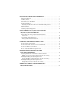
INSTALLING YOUR VOICE TERMINAL . . . . . . . . . . . . . . . . . . . . . . . . . 1 Distance Limitations . . . . . . . . . . . . . . . . . . . . . . . . . . . . . . . . . . . . . . . . . . . . . . . 1 Auxiliary Power . . . . . . . . . . . . . . . . . . . . . . . . . . . . . . . . . . . . . . . . . . . . . . . . . . . 1 General Notes for Installation . . . . . . . . . . . . . . . . . . . . . . . . . . . . . . . . . . . . . . . . 2 Desktop Installation . . . . . . . . . . . . . . . . . . . . . . . . . . . . .
INSTALLING YOUR VOICE TERMINAL IMPORTANT: For a fuller description of installing the 8400-Series voice terminals and procedures on administering these sets and programming such options as enabling/disabling the speakerphone or one-way speaker, enabling/disabling the Mute function, selecting ringing preference, or selecting handset and speaker volume control, see the 8400-Series Voice Terminals Instructions for Installation, Switch Administration, and Programming the Options, 555-015-725.
• • 1145B1 Bulk Power Supply (PEC: 2404-010) Battery for the 1145B1 (2 amp battery = PEC: 24700; or 5 amp battery = PEC: 24701) KS-22911 L2 (replaced by the MSP-1 Power Supply and 1151A1/A2 Power Supplies) — This power supply cannot be used with the 8411. NOTES: The MSP-1, the 1151A1 and A2, and the 1145B are global power supplies. It is recommended that the 1145A and the 1145B Bulk Power Supplies be used as auxiliary power for the 8434DX voice terminal.
jack for connecting an analog device such as a modem, answering machines, fax machines, audio teleconferencing equipment, or TTY machines commonly used by the hearing impaired. • Figure 4 shows the back of the 8434DX voice terminal. (Note that the jacks on the back of your voice terminal may be in a slightly different location.) 1. Turn the voice terminal face down on a flat surface. 2.
6. Snap one end of the coiled cord into the Handset jack. This jack is labeled . (On some 8403 voice terminals, you must thread the cord into the channel leading to the side edge of the voice terminal; the handset cord will then lead off the side of the voice terminal.) WARNING: Do not insert the handset cord into the Adjunct jack. It may cause equipment damage.
FIGURE 2: Line, Adjunct, and Handset Cord Routing for Desktop Installation on the 8411 Voice Terminal Analog Adjunct jack RS-232-D jack FIGURE 3: Connecting a PC for Use with PassageWay and Connecting an Analog Adjunct (These Jacks Are on the Rear of the 8411) 5
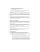
Routing channel LINE ! USE ONLY WITH COMMUNICATION CIRCUIT POWER SOURCE UL Expansion module jack Line jack EX MOD Lucent Technologies MADE IN U.S.A. LISTED Telephone Equipment 91B0 ® HAC > ABS< Adjunct jack Handset jack NOTE: The location of the jacks and the routing channel on the back of your voice terminal may differ slightly from the location shown in this figure. FIGURE 4: Line, Adjunct, Handset, and Expansion Module Cord Routing on the 8434DX Voice Terminal 7.
on, the voice terminal may not have power. In this case, check the connections and then verify that the particular voice terminal is administered on the DEFINITY switch.) Adjusting the 8405 and 8410 Voice Terminal Desktop Stand To provide better display visibility on the 8405D, 8405D Plus, and 8410D set, the desktop stand on these terminals can be installed in a high or low position. (When the voice terminal is shipped from the factory, the stand is in the low position.
Use these 2 tab slots for the high position Use these 2 tab slots for the low position Press inward Tab Tabs Slots Slots NOTE: The location of the slots may differ slightly from those in this figure.
Wall Installation NOTE: The 8403, 8405, and 8410 voice terminals can be wall-mounted. The 8411 and the 8434DX voice terminals CANNOT be wall-mounted. For wall-mounting, you need a 1-foot D8W line cord (not supplied with the voice terminal; Comcode: 103786760). To wall-mount the 8403, 8405, and 8410 voice terminals 1. Make sure the 8-conductor wall mount plate is in place. 2. Press down on the handset retainer hook located under the handset and slide it toward the top of the voice terminal. See Figure 6. 3.
4. Place the voice terminal face down on a flat surface and turn the terminal face down. 5. Remove the desktop stand which is attached to the base of the voice terminal by tabs on the top and back of the stand. See Figure 7. — Press inward on the top of the stand until you can lift the top of the stand out of the tab slot on the voice terminal. — Lift the bottom of the stand out of the lower tab slot(s). FIGURE 7: Removing the Desktop Stand on the 8403, 8405, and 8410 6.
Wall jack FIGURE 8: Placing the Voice Terminal onto the Wall Jack Mounting Studs 11. Snap the free end of the handset cord into the handset and place the handset in the cradle. NOTE: The handset hook you repositioned will hold the handset in place. 12. Lift the handset and listen for dial tone. If there is no dial tone, check all wire connections to make sure they are secure. Also, perform a self-test to see if the terminal is receiving power. (Press and hold down the Test button.
Attaching Adjunct Equipment If you are installing a speakerphone (Lucent Technologies models S101A, S201A, or QUORUM® CS201A), a headset adapter (Lucent Technologies model 500A1), or other adjunct that may be offered, follow these steps to connect the adjunct equipment to your voice terminal. The adjunct requires auxiliary power from either a local, individual power supply or a closet supply serving multiple phones. Refer to the adjunct's installation documentation for its power requirements. 1.
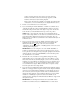
84xx Terminal KS-22911 power supply D6AP Wall jack Line ADJ D8W 400B2 D8AC 84xx Terminal Ex Mod 8434DX Wall jack D8W Line D8AC Other Expansion Module ADJ Line cord Line D6AP Adjunct Adjunct MSP-1 or the 1151A1/A2 Phonepower supplies (on the MSP-1 only) = Cord connections = Jack FIGURE 9: Connections for the 8434DX and All Telephones with Adjuncts Using an Individual Power Supply 13
USING THE RS-232-D JACK AND ANALOG ADJUNCT JACK ON THE 8411 See Figure 3 in the front of this manual for a drawing of the rear of the 8411 voice terminal. You can use the RS-232-D jack for connecting the 8411 to a PC for use with PassageWay Solution software. The Analog Adjunct jack can be used for connecting an answering machine, fax machine, modems, audio teleconferencing equipment or TTY machines commonly used by the hearing impaired.
WARNING: Do NOT connect the Analog Adjunct to the wall jack. It will cause equipment damage. NOTE: When an 8411 voice terminal is administered at a DEFINITY G3V4, Issue 3, switch, the voice terminal must be administered to use the appropriate analog telephone line. For more information on administration of the 8411, see “Switch Administration” later in this manual.
PassageWay Status Indications On 8411 voice terminals, the GREEN and RED lights next to Button #9 provide the following status indications for the PassageWay connection: PassageWay Status Green Light AT Command Mode Off PassageWay Mode On DCP Looparound Red Light On Off * Flash † Wink Flash Switch Link Down Wink EIA Out-of-Sync Flash Off On Flash Program Mode * A Flash is a repeating pattern of 500 ms ON and 500 ms OFF. † A Wink is a repeating pattern of 750 ms ON and 250 ms OFF.
LABELING THE DESIGNATION CARD The designation card is a removable card placed behind a transparent protective cover on which the user can type or print call appearance or feature assignments. In most cases, the voice terminal’s designation card is filled out before the user begins to use the set. Do not discard the blank button designation card. Instead, if there is a preprinted designation card, place it over the blank button designation card which comes with the voice terminal.
For the 8434DX Voice Terminal There are two Call Appearance/Feature Button Designation Cards for the 8434DX voice terminal: • • The smaller card contains two columns with five buttons in each column: the first column is labeled a through e; the second column is labeled f through j. The larger card also contains two columns with 12 buttons in each column. The button labels on this larger card are blank; that is, they are NOT prelabeled with letters like the smaller card.
• • • If a PC used for the PassageWay Solution software is connected to the 8411, type a “y” in the PassageWay field on the first administration screen. If an analog adjunct is connected to the 8411, type “analog” in the Data Option: field on the first administration screen. On the last administration screen, enter the appropriate information for the Analog Adjunct. PROGRAMMING OPTIONS ON THE 8411 VOICE TERMINAL Use the following procedures for selecting options for an 8411 voice terminal.
To select which channel (the I-1 Channel or the I-2 Channel) the Analog (T/R) Adjunct will use 1. While on-hook, press Shift . • The light next to Shift goes on. 2. Press Mute . • The light next to Shift goes off. 3. Enter the 2-digit code, “42” (“IC”). • • The red light next to Shift flutters. The current setting (either T/R ON I1 CHANNEL or T/R ON I2 CHANNEL) is shown on the display, if there is one. 4.
For a more detailed list of Analog Adjunct (Tip/Ring) status light indications, see “PassageWay and Analog Adjunct Status Indications on the 8411” earlier in this manual. To enable or disable the status lights for the Analog Adjunct interface 1. While on-hook, press Shift . • 2. The light next to Shift goes on. Press Mute . • The light next to Shift goes off. 3. Enter the 2-digit code, “25” (“AL”). • • The red and green lights next to Button #10 flutter.
Enabling/Disabling the Status Lights for the PassageWay Connection (For the 8411 Only) If a PC for the PassageWay Solution has been connected to the RS-232-D jack on the rear of the 8411, the user can use Button #9 (the next-to-last button in the second column) to see the status of the PassageWay connection. For a list of PassageWay indications, see “PassageWay and Analog Adjunct Status Indications on the 8411” earlier in this manual. To enable or disable the status lights for the PassageWay connection 1.
Write: Lucent Technologies BCS Publications Center P.O. Box 4100 Crawfordsville, IN 47933 Call: 1 800 457-1235 Outside US: 1 317 361-5353 When ordering any of these documents, be sure to specify the title and the “555” ordering number.
— DEFINITY Communications System Generic 2 and System 85 8411 Voice Terminal Quick Reference Guide, 555-104-770 — DEFINITY Communications System Generic 1 and Generic 3 and System 75 8434DX Voice Terminal User’s Guide, 555-230-856 — DEFINITY Communications System Generic1 and Generic 3 and System 75 8434DX Voice Terminal Quick Reference Guide, 555-230-857 — DEFINITY Communications System Generic 2 and System 85 8434DX Voice Terminal User’s Guide, 555-104-767 — DEFINITY Communications System Generic