DEFINITY® CALLMASTER® II and CALLMASTER® III Voice Terminals User and Installation Instructions AT&T 555-015-168 COMCODE 107319659 Issue 1, August 1994
bc cb WARRANTY All terms and conditions specified in your agreement with AT&T apply. NOTICE While reasonable efforts were made to ensure that the information in this document was complete and accurate at the time of printing, AT&T can assume no responsibility for any errors. Changes or corrections to the information contained in this document may be incorporated into future issues. TO ORDER COPIES OF THIS DOCUMENT Contact: AT&T Customer Information Center 2855 North Franklin Road P.O.
bc cb HEARING AID COMPATIBILITY This terminal is compatible with inductively coupled hearing aids as prescribed by the Federal Communications Commission. INTERFERENCE WARNING INFORMATION - Part 15 of FCC Rules Federal Communications Commission (FCC) Rules require that you be notified of the following: This equipment has been tested and found to comply with the limits for a Class A digital device, pursuant to Part 15 of the FCC Rules.
bc cb IMPORTANT SAFETY INSTRUCTIONS Only the most careful attention has been devoted to quality standards in the manufacture of your new voice terminal. Safety is a major factor in the design of every set. But, safety is YOUR responsibility too. Please carefully read the helpful tips listed below and on the next page. These suggestions will enable you to take the fullest advantage of your new voice terminal. Retain these tips for later use.
bc cb Service 1 Before cleaning, unplug the voice terminal from the modular wall jack. Do not use liquid cleaners or aerosol cleaners. Use a damp cloth for cleaning.
bc cb Contents Your CALLMASTER Voice Terminal ……………………………6 The Headset (or the Handset) ……………………………………6 The Recorder Interface ……………………………………………7 Organization of This Guide…………………………………………7 Conventions …………………………………………………………8 Feature Descriptions ………………………………………………9 Installation……………………………………………………………13 Checklist of Parts …………………………………………………13 Orderable Equipment ……………………………………………14 Installing the CALLMASTER Voice Terminals …………………15 Testing the Headset or Handset …………………………………20 Labeling and Installing
bc cb Your CALLMASTER Voice Terminal The AT&T CALLMASTER voice terminals referred to in this manual include the CALLMASTER II and the CALLMASTER III models. Both of these voice terminals have been specially designed for use with the Automatic Call Distribution (ACD) system and the many features of DEFINITY Generic 1, Generic 2, and Generic 3. The CALLMASTER II and the CALLMASTER III are identical in appearance.
bc cb If you have both a handset and a headset plugged into a CALLMASTER voice terminal, you may want to unplug the handset when you are not using it, since it can pick up nearby noises (such as papers being shuffled) which may be heard over the headset. THE RECORDER INTERFACE The CALLMASTER II with Recorder Interface is designed for recording calls on a standard analog tape recorder. [A recorder with AGC (Automatic Gain Control) is recommended.
bc cb CONVENTIONS The following conventions are used in the procedures: bbbbbbb xxxxx cbbbbbbbc b bbbbbb cbFeature bbbbbbc This box represents a call appearance button, which is used exclusively for placing or receiving calls. The button has a red appearance light and a green status light and is labeled with an extension number (shown as xxxxx). Each of these boxes represents a button to which a feature has been assigned. The button is labeled with a feature name.
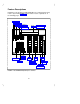
bc cb Feature Descriptions Familiarize yourself with your CALLMASTER voice terminal and its many features by reviewing Figure 1 below and the feature explanations on the following pages.
bc cb Starting at the top left of Figure 1 and continuing clockwise: A red light which goes on steadily when a message has been left for you. Message Light Drop/Test Button For disconnecting from a call or dropping b bbbbb the last party added to a conference call. When used with cbSelect bbbbbc , you can perform a self-test of your voice terminal lights and tone ringer. For setting up conference calls. With a DEFINITY Generic 1 or Generic 3, the conference can include up to six parties.
bc cb Adjunct Jack (on bottom of voice terminal) This jack is used to connect compatible adjunct equipment, such as an S101A or S201A Speakerphone, a 507A Adapter, or a 500A Headset Adapter, to your voice terminal. The jack is labeled . For turning off the voice transmitter in the headset or handset so the other person cannot hear you.
bc cb b bbbbbbbbbbbbbbbbbbbbbbbbbbbbbbbbbbbbbbbbb c c c c c c c c c c Headset c Jacks c c c c c c c c c c c c c c c c c c c c c c c c c c c c c c bbbbbbbbbbbbbbbbbbbbbbbbbbbbbbbbbbbbbbbbbc b FIGURE 2 The headset jacks on the side of the CALLMASTER On both sides of the CALLMASTER (II and III) voice terminals, as shown in Figure 2 above, there is a set of headset jacks. Use these jacks for connecting a headset to your CALLMASTER set.
bc cb Installation Use the following procedures to install your CALLMASTER voice terminal. b bbbbbbbbbbbbbbbbbbbbbbbbbbbbbbbbbbbbbbbbbbbbbbbbbbbbbbbbbbbbbbbbbb c IMPORTANT: ‘‘DEFINITY CALLMASTER II and CALLMASTER III c c Instructions for Programming the Options,’’ 555-015-169, is a brief set c c of instructions which includes procedures for setting the display for c c 1 or 2 lines and for controlling the Mute button.
bc cb ORDERABLE EQUIPMENT The following equipment can be ordered by using the appropriate Comcode: bbbbbbbbbbbbbbbbbbbbbbbbbbbbbbbbbbbbbbbbbbbbbbbbbbbbbbbbbbbbbbbbbbbbbbbbbbbbbbbbbbbb c c Orderable Equipment c c bbbbbbbbbbbbbbbbbbbbbbbbbbbbbbbbbbbbbbbbbbbbbbbbbbbbbbbbbbbbbbbbbbbbbbbbbbbbbbbbbbbb c c c c ITEM c COMCODE c bbbbbbbbbbbbbbbbbbbbbbbbbbbbbbbbbbbbbbbbbbbbbbbbbbbbbbbbbbbbbbbbbbbbbbbbbbbbbbbbbbbb c c c c CALLMASTER II Voice Terminal (with Recorder Interface) c c c c c Black 106693294 c c c Misty Cr
bc cb bbbbbbbbbbbbbbbbbbbbbbbbbbbbbbbbbbbbbbbbbbbbbbbbbbbbbbbbbbbbbbbbbbbbbbbbbbbbbbbbbbb c c Orderable Equipment (continued) c cbbbbbbbbbbbbbbbbbbbbbbbbbbbbbbbbbbbbbbbbbbbbbbbbbbbbbbbbbbbbbbbbbbbbbbbbbbbbbbbbbbb c c c c c ITEM COMCODE c bbbbbbbbbbbbbbbbbbbbbbbbbbbbbbbbbbbbbbbbbbbbbbbbbbbbbbbbbbbbbbbbbbbbbbbbbbbbbbbbbbb c cbbbbbbbbbbbbbbbbbbbbbbbbbbbbbbbbbbbbbbbbbbbbbbbbbbbbbbbbbbbbbbbbbbbbbbbbbbbbbbbbbbb c c c Handset D-Kit #182835 (white) 107318438 c bbbbbbbbbbbbbbbbbbbbbbbbbbbbbbbbbbbbbbbbbbbbbbbbbbbbb
bc cb b bbbbbbbbbbbbbbbbbbbbbbbbbbbbbbbbbbbbbbbbb c c c c c c c c c c c c c c c c c c c c c c c c c c Line Cord LINE Jack Adjunct Jack Adjunct Jack c c Routing Routing Channel Channel c c c bbbbbbbbbbbbbbbbbbbbbbbbbbbbbbbbbbbbbbbbbc b FIGURE 3 The LINE jack, adjunct jack, and routing channels Important Notes on Installation The total distance between the CALLMASTER II voice terminal with Recorder Interface and the recording device should not exceed 200 feet.
bc cb DCP Line Interface The DCP line interface is a standard D8W 8-wire modular cord. One pair is used for balanced digital transmission to the PBX switch; another pair is used for balanced digital reception from the PBX switch. A third pair in the 8-wire modular cord provides auxiliary power for the adjunct, and a fourth pair is used only by the CALLMASTER II with Recorder Interface to provide the analog Record Out signals to an external tape recorder.
bc cb Figure 4 shows how a CALLMASTER II with Recorder Interface should be configured through the wall jack with the DEFINITY PBX, an adjunct power source, and the recording device. NOTE: Typically, a 104A wall jack is used in this type of configuration.
bc cb BL-W (REC2) W-O (0D1) O-W (0D2) W-G (ID1) G-W (ID2) W-BR (P1-) BR-W (P2+) W-BL (REC1) b bbbbbbbbbbbbbbbbbbbbbbbbbbbbbbbbbbbbbbbbb c c c c Adjunct Power c Recording c PBX Device c c c c Twisted Pair c Wire c c c c c c c c c c c White Connecting Block, c 110-Type c c c 4-Pair Cross c c Connect c c Blue Connecting Block, 110-Type c c c c House Cable c c c c 104A Wall c Jack c c c D8W Cord c c c c CALLMASTER Voice c Terminal c c c c c c bbbbbbbbbbbbbbbbbbbbbbbbbbbbbbbbbbbbbbbbbc b CALLMASTER FIGURE 4
bc cb TESTING THE HEADSET OR HANDSET 1 If you are using a handset, use the installation instructions that come with the handset kit to install the handset cradle. 2 Plug in the headset or the handset, press a call appearance button, and listen for dial tone. d If you do not hear dial tone, press another call appearance button. You may also want to check that the cords are connected securely at both ends.
bc cb b bbbbbbbbbbbbbbbbbbbbbbbbbbbbbbbbbbbbbbbbb c c c Button Designation c Strips c c c c c c c c c c c c c c c c c c c c c c c c c c c c CALLMASTER c c c bbbbbbbbbbbbbbbbbbbbbbbbbbbbbbbbbbbbbbbbbc b Mute Log In Release FIGURE 5 Inserting the designation strips 16 fc cf
bc cb Feature Procedures The following features can be used immediately. The procedures in this section give short, step-by-step instructions for using each of these features. For your convenience, beginning with the Conference feature, the features are listed alphabetically. GOING OFF-HOOK When the headset or handset is plugged into the terminal, it is immediately off-hook.
bc cb DISCONNECTING FROM CALLS You can disconnect from a call in several ways: bbbbbbbb Release to disconnect from any type of call in approximately d Press cbbbbbbbbc one-tenth of a second. This method is faster than waiting for a caller or trunk to disconnect and enables you to perform other ACD or voice terminal procedures sooner. You do not hear dial tone after bbbbbbbb Release .
bc cb aaaaaaaaaaaaaaaaaaaaaaaaaaaaaaaaaaaaaaaaaaaaaaaaaaaaaaaaaaaaaaaaaaaa CONFERENCE aaaaaaaaaaaaaaaaaaaaaaaaaaaaaaaaaaaaaaaaaaaaaaaaaaaaaaaaaaaaaaaaaaaa To add another party to an existing call Note: If your CALLMASTER voice terminal is connected to a DEFINITY Generic 1 or Generic 3, the conference call can include up to six parties. If your CALLMASTER is connected to a DEFINITY Generic 2, the conference can include up to three parties.
bc cb aaaaaaaaaaaaaaaaaaaaaaaaaaaaaaaaaaaaaaaaaaaaaaaaaaaaaaaaaaaaaaaaaaaa DROP aaaaaaaaaaaaaaaaaaaaaaaaaaaaaaaaaaaaaaaaaaaaaaaaaaaaaaaaaaaaaaaaaaaa To disconnect from an active 2-party call bbbbbbb Drop 1 Press ccbbbbbbbc Test c d You hear dial tone bbbbbbb bbbbbbbb Drop Release instead of ccbbbbbbbc NOTE: You may press cbbbbbbbbc Test c to disconnect bbbbbbbb Release you will not hear dial tone. faster.
bc cb aaaaaaaaaaaaaaaaaaaaaaaaaaaaaaaaaaaaaaaaaaaaaaaaaaaaaaaaaaaaaaaaaaaa MUTE aaaaaaaaaaaaaaaaaaaaaaaaaaaaaaaaaaaaaaaaaaaaaaaaaaaaaaaaaaaaaaaaaaaa To prevent the other party from hearing you bbbbbb Mute 1 Press cbbbbbbc bbbbbb Mute goes on; other party cannot hear you d Red light next to cbbbbbbc 2 When byou want to resume the conversation with the other party, bbbbb Mute again press cbbbbbbc d Red light next to button goes off; caller can hear you again NOTE: The Mute feature has no effect when an a
bc cb Select Ring (and Ringer Volume) (Continued) You can raise or lower the volume of the tone ringer under the following conditions: d The CALLMASTER is on-hook, and the headset is unplugged d The voice terminal is off-hook on the external speakerphone d A call is ringing at the voice terminal d You are in the process of selecting a personalized ringing pattern for your voice terminal.
bc cb aaaaaaaaaaaaaaaaaaaaaaaaaaaaaaaaaaaaaaaaaaaaaaaaaaaaaaaaaaaaaaaaaaaa TRANSFER aaaaaaaaaaaaaaaaaaaaaaaaaaaaaaaaaaaaaaaaaaaaaaaaaaaaaaaaaaaaaaaaaaaa To send an existing call to another extension or outside number bbbbbbbb Transfer 1 Press cbbbbbbbbc d Green light at call appearance flutters d Present call is put on hold d You are given a new call appearance, and you hear dial tone 2 Dial number where call will be transferred d You hear ringback tone d If the call is answered, remain on line and anno
bc cb Technical Description Physical Dimension and Weight The CALLMASTER voice terminal can only be desk-mounted; it cannot be wall-mounted. The CALLMASTER voice terminal measures d 8.5 inches deep d 11.0 inches wide d 4.25 lbs Power Requirements The CALLMASTER voice terminal is line powered from the PBX switch. The CALLMASTER will operate in voltage ranges of 42.5 to 56.5 volts. See the Installation section for operating range requirements.