
User`s guide
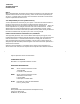
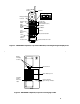
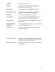

Top Hook
Power Plug
Connector
Card Edge
Snap Lock
Line Connector
LED
Indicators
Power
Radio
Pass
Antenna
Figure 3. MDW 9000 Telephone, Radio Module
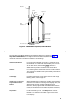
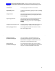
The handset of the MDW 9000 has the following features as shown in Figure 1,
Top View of Handset (the list begins with the Headset On/Off button and
continues clockwise around the handset in the drawing) :
Headset On/Off Button For turning the headset on and off. Located on top of
the handset, it is used when the headset jack is in use.
At all other times, the headset
On/Off button is
deactivated to prevent accidental call termination.
Antenna For receiving the transmissions from the radio module.
This antenna is flexible and is permanently attached to
the handset.
LCD Display Provides information on the status of lines and range,
battery power, mute usage, etc.
Outside Line or Intercom/
Programmable Feature
Buttons
When labeled with an extension number, these buttons
indicate lines used for incoming and outgoing calls (call
appearances) and for using the telephone as an
intercom; when programmed and labeled with feature
names, these buttons access features (feature buttons).
Drop Button For disconnecting a call. The Drop button is NOT
labeled. It is located in the lower right corner of the
LCD display.
3