AT&T MERLIN LEGEND™ Communications System Key System Planning
Copyright © 1991 AT&T All Rights Reserved Printed in U.S.A. AT&T 555-610-112 Issue 1 August 1991 Notice Every effort was made to ensure that the information in this book was complete and accurate at the time of printing. However, information is subject to change. Federal Communications Commission (FCC) Information For important FCC interference, registration, and repair information, see ‘Customer Support Information” in this book. Trademarks Accunet is a registered trademark of AT&T.
ERRATA MERLIN LEGEND™ Communications System Key System Planning 555 - 610 - 112 Ignore all references to the small processor module. The MERLIN LEGEND™ Communications System offers only one processor module. This processor module is referred to as a large processor module in this document. Page 1-6 Table 1-2, Control Unit Space Requirements: Ignore the reference to a small system.
Contents Customer Support Information 1 2 ■ Support Telephone Number ■ FCC/DOC Information ■ Security ■ Warranty vii vii xi xi About This Book ■ Related Documentation ■ How to Order Books ■ Additional Ordering Information ■ Product Safety Labels ■ How to Comment on This Book xiii xiv xiv xv xv xv Preparation 1-1 ■ System Components ■ Location of Control Unit ■ Telephone User Survey ■ Floor Plan 1-1 1-5 1-7 1-11 Control Unit 2-1 2-1 2-8 2-11 Lines 3-1 3-1 3-7 3-36 ■ Modules ■ System Operatin
Contents 4 Features Telephone Features Operator Features ■ Group Assigned Features ■ System Features ■ ■ 5 Modiflcations ■ ■ Preparation Adding to the System 4-1 4-1 4-5 4-8 4-20 5-1 5-1 5-2 A Forms A-1 IN Index IN-I ii Contents
Figures 1 Preparation 1-1 1-2 1-3 2 1-2 1-8 1-12 Control Unit 2-1 2-2 2-3 2-4 2-5 3 System Components Employee Communication Survey Form Floor Plan Line and Station Modules Sample Control Unit Diagram Two-Digit Numbering Plan Three-Digit Numbering Plan Set Up Space Numbering Plan 2-2 2-7 2-19 2-21 2-23 Partially Completed Form 2c, System Numbering — Line Jacks Sample Network Planning Map Factory-Set Assignment, Digital/lSDN (MIX) Telephones Factory-Set Assignment, Analog Multiline Telephones Digit
Tables 1 Preparation 1-1 1-2 1-3 2 Line Jack Types Coding Line Type Services on the DS1 Facility Line Compensation Settings Timers and Counters Guide to DS1 Facilities Ordering 3-2 3-3 3-14 3-18 3-24 3-32 Required Line and/or Station Modules Adding New Lines Adding Auxiliary Equipment Adding New Stations 5-3 5-4 5-5 5-5 Key System Forms A-1 Forms A-1 iv Contents 2-4 2-12 2-14 Modifications 5-1 5-2 5-3 5-4 A Module Capacities Station Jack Types Maximum Number of Operator Positions Lines 3-1 3
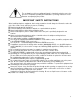
The exclamation point in an equilateral triangle is intended to alert the user to the presence of important operating and maintenance (servicing) instructions in the literature accompanying the product. IMPORTANT SAFETY INSTRUCTIONS When installing telephone equipment, basic safety precautions should always be followed to reduce the risk of fire, electric shock, and injury to persons, including: Read and understand all instructions. Follow all warnings and instructions marked on or packed with the product.
vi
Customer Support Information Support Telephone Number AT&T provides a toll-free customer Helpline (1-800-628-2888)24 hours a day (U.S.A. only). Call the Helpline, or your authorized dealer, if you need assistance when installing, programming, or using your system. Federal Communications Commission (FCC) Electromagnetic Interference Information This equipment has been tested and found to comply with the limits for a Class A digital device, pursuant to Part 15 of the FCC Rules.
Customer Support Information ■ For connection to off-premises stations, report the FIC OL13C and SOC 9. OF. ■ If this equipment is to be connected to digital service (1.544 Mbs), the FIC is 04DU9-B for D4 framing format or 04DU9-C for extended framing format, and SOC 6.0P. ■ If this equipment is to be connected to DID facilities, the FIC is 02 RV2-T, and the SOC is 9.0F. ■ The ■ quantities and USOC numbers of the jacks required.
Customer Support Information To prevent overloading, the Load Number (LN) assigned to each terminal device denotes the percentage of the total load to be connected to a telephone loop used by the device. The termination on a loop may consist of any combination of devices subject only to the requirement that the total of the Load Numbers of all the devices does not exceed 100. DOC Certification No. 230 4095A CSA Certification No. LR 56260 Load No.
Customer Support Information x Customer Support Information
Customer Support Information Security of Your System—Preventing Toll Fraud As a customer of a new telephone system, you should be aware that there exists an increasing problem of telephone toll fraud. Telephone toll fraud can occur in many forms, despite the numerous efforts of telephone companies and telephone equipment manufacturers to control it. Some individuals use electronic devices to prevent or falsify records of these calls.
Customer Support Information If you purchased your system directly from AT&T, AT&T will perform warranty repair in accordance with the terms and conditions of the specific type of AT&T maintenance coverage you selected. A written explanation of AT&T’s types of maintenance coverage may be obtained from AT&T by calling 1-800-247-7000. If you purchased your system from an AT&T authorized reseller, contact your reseller for the details of the maintenance plan applicable to your system.
About This Book This book tells you how to plan a Key or Behind Switch communications system. It is intended for persons who plan, implement, coordinate, and manage the system (called "system managers”). In addition to this book, you will need ■ copies of the Key System Planning Forms You will use these forms to ■ outline the decisions you make about how the system should be assembled and programmed—for example, what trunks will be connected to the control unit and in what order.
About This Book Related Documentation The following types of books are available to help you set up, use, and maintain the communications system: ■ reference ■ setup and modification ■ telephone user support ■ operator guides ■ miscellaneous How to Order Books The books needed for operating the communications system were supplied with the system.
About This Book MERLIN LEGEND Book Title Order Number Operator Guides Analog Direct-Line Consoles Operator’s Guide Digital/lSDN Direct-Line Consoles Operator’s Guide Digital/ISDN Queued Call Console Operator’s Guide 555-610-131 555-610-132 555-610-133 Miscellaneous Calling Group Supervisor’s Guide 555-610-130 Additional Ordering Information For information on ordering replacement parts, accessories, and other equipment that is compatible with the system, see Appendix A in System Reference.
Preparation Several actions must be completed before the system is installed: ■ Review ■ the system’s hardware, features, and operation. Arrange for the location of the control unit. ■ Survey ■ Find telephone users on their needs. or create a floor plan. System Components To tailor the system for your company, you must know the number and types of telephones, outside lines, and adjuncts that were ordered. Review the AT&T Equipment List provided by your AT&T representative or authorized dealer.
Preparation Figure 1-1 System Components 1-2 System Components
Preparation 1. Control Unit The backbone of the system, consisting of the basic and expansion carriers, power supply module, processor module, and line and station modules. The control unit connects telephone company lines with stations such as telephones and adjuncts. 2. Line/Trunk and Station Modules. The components that connect telephone company lines and terminal equipment such as telephones, external alerts, and fax machines via jacks to the control unit. 3. Basic Carrier.
Preparation 13. Off-Premises Telephone (OPT). A single-line, touch-tone or rotary, industrystandard telephone located in a different building from the control unit. 14. External Alert. An alerting device such as bells, chimes, and strobe lights that connect to a jack on a012 basic telephone module or a 008 OPT module, or to an MFM or Supplemental Alert Adapter (SAA). 15. Digital Data Terminal.
Preparation Location of the Control Unit Before installation, choose a room, closet, or other area where the system control unit can be mounted on the wall. The area must meet the environmental requirements in Table 1-1.
Preparation Table 1-1 Continued Cautions The AC outlet for control unit should not be switch controlled. ■ Plugging the control unit into an outlet that can be turned on and off by a switch can cause accidental disconnection of the system. ■ ■ The AC outlet must be properly grounded via an AC receptacle for a 3-prong plug. Do not install the control unit outdoors. ■ Do not place the control unit near extreme heat (furnaces, heaters, attics, or direct sunlight).
Preparation Telephone User Survey The features and calling privileges you assign to each employee’s telephone ensure that employees get the most benefit from the system. If you were not involved in the planning and decision-making for the system, find out from your management and your AT&T representative or authorized dealer what telecommunications needs were identified.
Preparation Name Room Extension Name of work group (Sales, Customer Service) Please answer each question below. 1. Do you regularly use any of the following outside lines? (Check any that apply) ❑ ❑ ❑ ❑ 2. WATS FX (foreign exchange) Tie None of the above or don’t know Are your phone calls covered when you’re away from your desk? ❑ No ❑ Yes 3.
Preparation 6. Do you have a data terminal or personal computer at your workstation? ❑ No Do you expect to get one within the next year? ❑ No ❑ Yes ❑ Yes 7. Do you have a ❑ No ❑ Yes or ISDN 7500B Data Module? Do you use account codes for charge-back of calls? ❑ No ❑ Yes Please list all the codes you use (attach another sheet if necessary): 8. Approximately how many times do you transfer calls? 9.
Preparation Use the information in Table 1-3 to interpret and analyze the results of the Employee Communication Survey. Table 1-3 Employee Communication Survey — Sample Analysis 1. Types of lines used Indicates toll calling habits. In most cases, assigning a button for each line is not necessary. 2.
Preparation Floor Plan Use a floor plan to make planning more manageable and to ensure that the correct telephone equipment is assigned to each employee. If your organization is moving to a new location, a floor plan may already be prepared and you may be able to get a copy of it from your management. Create a floor plan in two phases: 1. Indicate the location and type of telephones, adjuncts (fax, answering machines, etc.), and data terminals. 2.
Preparation Figure 1-3 Floor Plan As shown in Figure 1-3, the floor plan does not need to be elaborate or to scale. The telephone symbol should be large enough to accommodate the size of telephone and the assigned number, and if you find it helpful, the name of the employee. Keep the floor plan. You will refer to it during planning and complete it (by filling in extension numbers) when you get to “System Numbering” in Chapter 2.
Control Unit Planning the control unit consists of deciding how to place the modules, setting the system operating conditions, and numbering the system. Modules Certain modules are required for every system: ■ Processor module contains the memory that controls the system software and features. It also contains the software and firmware that support built-in system diagnostics and the built-in data modem used for remote maintenance and system programming.
Control Unit FIgure 2-1 Line and Station Modules 2-2 Modules
Control Unit The lines and stations that can be connected to the jack types shown in Figure 2-1 are described below: 1. A DS1 line jack connects a Digital Signal 1 (DS1) facility provided by the telephone company. The DS1 facility can be set for either T1 or Integrated Services Digital Network Primary Rate Interface (ISDN-PRI) operation. The DS1 facility programmed for T1 operation supplies 24-channel emulation of any combination of ground-start (GS), loop-start (LS), and tie trunks.
Control Unit Table 2-1 Modules Capacities Station Jacks Modules Line Jacks 100D 1 DS1 facility (ISDN-PRI or T1) 400EM 4 4-wire E&M tie trunks 400 4 LS linrs with 4 TTR* 1 PFT jack 400 GS/LS/TTR 4 GS/LS lines with 4 TTR* 1 PFT jack 800 8 LS lines 2 PFT jacks 008 OPT 2 TTR* 8 OPT jacks 800 GS/LS 8 GS/LS lines 2 PFT jacks 008 8 analog jacks 008 MLX 8 digital jacks 012 2 TTR* 12 basik jacks 408 4 LS lines 8 analog jacks, 1 PFT jack 408 GS/LS 4 GS/LS lines 8 analog jacks, 1 P
Control Unit Station capacity is the number of stations that can be connected to the control unit, and it equals the number of physical jacks on the line and station modules. See “System Numbering” in this chapter for detailed information.
Control Unit ■ Group all 100D and 400EM modules together according to type, whenever possible, to save time in system programming. Each physical jack on the control unit is numbered sequentially from left to right and bottom to top: ■ Station jacks are numbered from 1 to 144. ■ Line jacks are numbered from 1 to 80. This sequence of numbers is called the "logical ID.
Control Unit Figure 2-2 Sample Control Unit Diagram Modules 2 - 7
Control Unit System Operating Conditions Use the “Control Unit Diagram” on Key System Form 1 as a reference and mark the “System Operating Condtions” section of that form.
Control Unit Mode of Operation See System Reference for more information on modes. Your system is registered with the FCC to operate as a Key system. However, you can program the system to operate in any of three modes: ■ Hybrid/PBX ■ Key (the factory setting) ■ Behind Switch The mode of operation determines ■ how outside lines are provided to users ■ the types of operator consoles allowed ■ the features available and how they work.
Control Unit In the Behind Switch mode single-line telephones can be programmed to select only the prime line (the user cannot make inside calls or use system features) or to select the intercom button followed by the prime line or outside line (the user can place and receive inside calls and use system features). Planning Form Instructions Under the "Set System Mode" heading on Form 1: 1. Check "Key" if you want your system to operate in the Key mode. 2.
Control Unit System Numbering System numbering is the process of assigning extension numbers to stations (telephones and adjuncts), calling groups, paging groups, Park zones, and Remote Access. The instructions is this chapter deal only with assigning extension numbers to stations. Number the stations in two stages: Stage One. Decide in what order to connect the telephones and other equipment to the control unit.
Control Unit Station Jack Connections Planning station jack connections consists of identifying the jack types and matching the telephones and other equipment to the jacks that support them.
Control Unit Planning Form Instructions In the "Jack Type" column of Form 2a, indicate the type of each station jack next to its logical ID. Jacks for Primary Operator Position 1 . Check "A" if the jack is Analog, "D" if Digital, or "B" if Basic telephone. 2 . The system reserves 12 logical IDs for the 008 OPT module even though only 8 are used. Cross off the last 4 logical IDs (they cannot be used).
Control Unit Table 2-3 Maximum Number of Operator Positions Telephone Type Processor Module Size MLX-20L MLX-28D Small 6 MLX-20L MLX-28D Large 8 Analog multiline telephones Small or Large 8 Maximum Positions Assign DLCs to only the first and fifth station jacks on a digital or analog module. This includes DLC positions used for calling group supervisors and for the optional Call Management System (CMS). The CMS equipment is connected to analog station jacks that are assigned as DLC positions.
Control Unit ■ Simultaneous Voice and Data. A user whose telephone has this feature can use the telephone and a data terminal at the same time. (MLX telephones have this feature without requiring a second station jack.) An analog multiline telephone with either one of these features requires two consecutive analog station jacks on the control unit. The jacks are an oddnumbered analog station jack and the next higher (even-numbered) analog station jack.
Control Unit Planning Form Instructions Use the Floor Plan and AT&T Equipment List to verify that you have located all remaining MLX telephones and adjuncts to them. On Form 2a, mark the station jack assignments for the remaining MLX telephones: 1. In the "Jack Type" column, make sure there is a "D" checked next to the logical ID for each digital station jack. 2. In the "Person, Location, or Function" column, identify each MLX telephone by person, location, or function.
Control Unit Jacks for Tip/Ring Equipment and Applications See System Reference for more information on applications. Use these instructions only if the system includes 012 or 008 OPT modules. Assign the basic telephone jacks on the 012 or 008 OPT modules to any tip/ring equipment such as single-line telephones, fax machines, or answering machines. Tip/ring equipment connects directly to an outside line and works on a single pair of wires.
Control Unit System Renumbering Use these instructions to decide whether to keep the factory-set extension numbers or to change them to numbers taylored to your company — for example, extension numbers that match room numbers. The system offers three numbering plans, as shown on Form 2a, System Numbering — Station Jacks. Each plan allows you to renumber all or selected extensions.
Control Unit Operator Console (not flexible) 0 Stations 10 — 19 Stations 20 — 29 Stations 30 — 39 Stations 40 — 49 Stations 50 — 59 0 1 2 3 4 5 6 7 8 9 Main Pool 7 0 A Extra Stations Stations 60 — 67 6800 — 6885 MFMs & 7500Bs Calling Group 710 — 767 770 — 791, 7920 — 7929 Park Lines 801 — 880 881 — 888 ARS Access (Hybred/PBX Mode)/Idle Line Access 9 Extra Adjunct 6900 — 6985 Page 793 — 799 Pools B 890 — 899 Figure 2-3 Two-Digit Numbering Plan A = 800-Listed Directory Number B = 889—Remote Access Each
Control Unit The unshaded areas of the two-digit numbering plan in Figure 2-3 indicate the extension numbers available for reassignment. This means that you can change selected extension numbers to one of the available numbers, for example, extensions 6886 through 6899. If the available numbers shown do not meet your needs, consider the three-digit numbering plan. Planning Form Instructions Use Figure 2-3 as you record extension number information. 1. 2. 3.
Control Unit Operator Console (not flexable) 0 Stations 100—199 0 1 2 Stations 200—243 MFMs/7500Bs 300—399 3 MFMs / 7500Bs 400 — 443 4 5 6 Main Pool 70 7 8 A 9 Calling Group Page 770— 791, 7920—7929 793—799 L i n e s Park Pools 801—879 890—899 881—888 B ARS Access (hybred/PBX Mode)/Idle Line Access 9 Figure 2-4 Three-Digit Numbering Plan A = 800—Listed Directory Number B = 889—Remote Access All stations are assigned a 3-digit extension number beginning with extension 100 and ending with extension
Control Unit The unshaded areas of the three-digit numbering plan in Figure 2-4 indicate the extension numbers available for reassignment. This means you can change the extension number automatically assigned by the system to one of the available numbers, for example, extension number 244 through 299. If the available numbers shown are not adequate to meet your needs, consider the set up space numbering plan. Planning Form Instructions Use Figure 2-4 as you record the extension number information. 1 .
Control Unit Operator Console (not flexible) 0 0 1 2 3 4 5 6 7 Main Pool 8 A 70 Stations MFMs/7500Bs 7100—7243 Calling Group Page 7300—7443 770—791, 7920—7929 793—799 9 Park Lines 881—888 801—880 B Pools 890—899 ARS Access (Hybrid/PBX Mode) /Idle Line Access 9 Figure 2-5 Set Up Space Numbering Plan A = 800—Listed Directory Number B = 889—Remote Access As shown in Figure 2-5, the system assigns extension numbers in the 7100 to 7243 range to stations.
Control Unit Planning Form Instructions Use Figure 2-5 as you record extension number information. 1 . If the system includes Digital station adjuncts: ■ Locate Key System Form 2b, System Numbering — Digital/ISDN Ststion Adjuncts. ■ Write the 4-digit extension number — the extension number from Form 2a increaed by 200 (within the range 7300–7443)—in the "Factory Set Extension No" column of Form 2b. 2 . Under the "Renumber System" heading of Key System Form 2a: ■ Check "Set Up Space.".
Lines Planning for lines consists of deciding how to connect outside lines to the system, selecting options for how those lines will work, and assigning lines to user stations. Line Connections Plan line connections by identifying line jack types and matching outside lines and auxiliary equipment to the jack types that support them.
Lines Table 3-1 Line Jack Types Used to Connect Line Jack Type Module Type Loop-start (LS) 400 800 408 Ground-start/Loop-start (GS/LS) 400 GS/LS/TTR 800 GS/LS 408 GS/LS Line Type ■ ■ ■ ■ Equipment Basic Special purpose — FX, WATS Music-on-Hold Loudspeaker paging systems Maintenance Alarm Basic Special purpose — FX, WATS Music-on-Hold Loudspeaker paging systems Maintenance Alarm Tie 400EM Tie DS1 100D T1 ISDN-PRI If the system has 1OOD (DS1) modules, keep in mind that 24 logical IDs an
Lines Planning Form Instructions Review the module listed on the "Contrrol Unit Diagram" on Form 1. On Key System Form 2c, System Numbering — Line Jacks: 1. Write the type of each line jack in the control unit in the "Jack Type" column. Use the codes shown in Table 3-2. For systems that include the 100D module: 2. 3. If the module is used only to emulate lines: ■ Fill in the jack type codes for those lines (T1-GS, T1-LS, or T1-Tie).
Lines Jacks for Outside Lines Identify the specific outside lines you want to connect to each loop-start and ground-start/loop-start line jack. Connect outside lines to a continuous sequence of line jacks on the control unit, beginning with the first line jack (logical ID 1). Use line jacks at the beginning of the sequence for basic loopstart lines. Use jacks later in the sequence for special-purpose lines such as WATS or FX (foreign exchange).
Lines Key System Form 2c System Numbering — Line Jacks Music-on-Hold, Logical ID Source Loudspeaker Page, Logical ID Logical ID 1 2 3 4 5 6 7 8 9 10 11 12 13 14 15 Jack Type (LS, GS, Tie, DS1 ) LS LS LS LS LS LS LS LS Maintenance Alarm, Logical ID Loop Start Reliable Disconnect ✓ NO ✦ ❑ Yes ❑ Line Type Line (Basic LS, Telephone Number or Number WATS, FX, etc.
Lines Jacks for Auxiliary Equipment Use these instructions only if the system has auxiliary equipment such as Music-on-Hold. Auxiliary equipment can be connected only on loop-start (LS) or groundstart/ loop-start (GS/LS) jack types. You cannot use a line jack on a 100D or 400EM module for auxiliary equipment, If you plan to use Music-on-Hold, designate a line jack for the music source such as a radio, tape player. stereo system, or Magic on Hold equipment.
Lines Line Options Choose from the following options for the outside lines connected to the system and record your decisions on Key System Form 2c, System Numbering — Line Jacks: ■ Loop-Start Disconnect Reliability ■ Rotary Dial Lines ■ Toll Prefix Dialing Requirements (Toll Type) ■ Hold Disconnect If the system includes any or all of the following additional line options, mark the Outside Lines forms (3a, 3c, and 3D): ■ Remote Access ■ DS1 Facility ■ Tie Trunks Loop-start Disconnect Reliab
Lines Rotary Dial Lines The system is factory set to generate touch-tone signals when users dial outside calls. Identify any rotary dial lines that are connected to the system so that rotary dial signals can be used for these lines. Note: Touch-tone single-line telephone users cannot make calls using lines programmed for rotaary operation. Check with your local or long-distance telephone company to determine which, if any, lines connected to the system are rotary dial lines.
Lines Planning Form Instructions In the "Short Hold Disconnect Interval" column of Form 2c, check "Yes" next to any lines that you want to change from the long (450mn) interval to the short (50 ms) interval. See "Loop-Start Disconnect Reliability” earlier in this section. Note: Be sure you have checked "No" for "Loop-Start Reliable Disconnect" if your local telephone company uses a Short Hold Disconnect interval. Remote Access Use these instructions only if remote users need access to the system.
Lines You can provide security for the system by requiring that people using Remote Access dial a password or barrier code to call into the system. When barrier codes are required, the caller dials a 4-digit number after the Remote Access special dial tone and then hears the system dial tone. CAUTION Under applicable tariffs, the customer is responsible for any charges incurred through the remote use of system facilities.
Lines Planning Form Instructions—Continued 2. Under the heading "Automatic Callback" at the top of Form 3a: ■ ■ Check "Disable" if you do not want remote callers to use this feature. Check "Enable" to allow this feature to remote callers. 3. Under the heading "Barrier Codes for Tie Trunks": ■ Check "Yes" if you plan to assign barrier codes to these lines. ■ Check "No" if no barrier codes are planned. 4. For "Barrier Codes for Non-Tie Lines": ■ Check "Yes" if you plan to assign barrier codes.
Lines Barrier Codes To help safeguard against unauthorized system access, the system can be programmed to require that remote users enter a barrier code before gaining access to the system. AT&T strongly recommends the use of barrier codes. CAUTION Under applicable tariffs, the customer is responsible for any charges incurred through the remote use of system facilities. Precautions should be taken to prevent unauthorized use of the system’s outside lines by remote callers, also called toll fraud.
Lines DS1 Facility (100D Module) Use these instructions only if the system has a 100D module. Because of the complexity of DS1 facility planning, consult with your AT&T representative or authorized dealer as you work through these instructions. A Digital Signal 1 (DS1) facility is a transmission system that transports digital signals in the DS1 format. The 100D module is the interface that allows the connection of DS1 facilities to the system.
Lines Type of Service The system supports two types of service for DS1 facilities: T1 and Integrated Services Digital Network Primary Rate Interface (ISDN-PRI). T1 service (the factory setting) transmits and receives voice, and analog data; ISDN-PRI transmits and receives voice and analog and digital data. Table 3-3 shows the kinds of services available through a DS1 facility and specifies the type of service that supports them.
Lines Table 3-3 Continued T1* ISDN-PRI x x Service Description Software Defined Network (SDN) A virtual private networking service for voice and circuit-switched analog data calls (up to 56 kbps). SDN lets businesses use portions of the AT&T Switched Network in concert with their dedicated private line networks. However, the system does not support "uniform dialing plan,” which is necessary for complete integration with SDN.
Lines Planning Form Instructions On Key System Form 2c, System Numbering — Line Jacks, in the "Jack Type" column: 1. Find all lines listed as "PRI" ■ See “Signaling Mode” in this chapter. Write the kinds of service connected to each channel in the "Line Type" column. Note: You cannot use the 24th channel for services. ■ 2 . Write "unequipped" in the "Line Type" column for any channel not used at this time.
Lines Two methods of framing can be used by a 100D module, but the framing chosen must match the framing at the far end: Line Code ■ D4 Framing Format The system is factory set for the most common framing format, D4 framing. A D4 frame consists of 24 eight-bit time slots and one framing bit. To synchronize the signals, the receiving equipment uses the framing information to identify the start of each frame and to identify which frames contain signaling information.
Lines Line Compensation Line compensation adjusts for the amount of cable loss in decibels (dBs). It is based on the length of cable between the 100D module and the CSU or between the module and another far-end connection—for example, a line repeater. The factory setting is a value of 1, which allows a maximum loss of 0.6 dB. The other possible settings are shown in Table 3-4 (based on 22-gauge cable). Table 3-4 Line Compensation Settings Setting dB Loss Cable Feet 1* -0.6 0–133 2 -1.
Lines Clock Synchronization Clock synchronization is an arrangement in which digital facilities operate from a common clock. Whenever digital signals are transmitted over a communications link, the receiving end is synchronized with the transmitting end to receive the digital signals. The system can synchronize itself to the far-end connection by extracting the timing signal from the DS1’s incoming digital stream.
Lines Planning Form Instructions—Continued 10. If installing more than one 100D Module, decide which Module, if any, provides the primary synchronization. ■ If Module 1 provides clock synchronization, check "Primary" in the first column (the factory setting). ■ If Module 2 (or Module 3) provides clock snychronization, check "Primary" in the column that describes that 100D module. ■ If the synchronization source is other than through a 100D module check "None".
Lines Planning Form Instructions—Continued 13. Channel Service Unit Setting for T1 Emulation Under the "Signaling Mode" heading of Form 3c, in all the columns that describe T1 Modules: ■ Check "RBS" to retain the factory setting of robbed-bit signaling. ■ Check "CCS" to change the factory setting to common-channel signaling. Use these instructions only if the 100D module type of service is T1 and outside lines are to be emulated.
Lines Telephone Number To allow the system to route calls to the correct destination, you can assign a telephone number consisting of up to 12 digits. The factory setting is no telephone number is assigned. If you assign a telephone number to a channel, it must match the number that is dialed by the outside caller and sent to the system by the network. The numbers sent by the network are furnished by the ISDN-PRI service provider.
Lines Test Telephone Number For each 100D module with an ISDN-PRI service type, you can assign a test telephone number that is used for maintenance by the service provider. See “B-Channel Groups" later in this chapter. The factory setting is that a test telephone number is not assigned. The number you assign must be the same number as that furnished by the ISDN-PRI service provider.
Lines Table 3-5 Timers and Counters Name Description Factory Setting Allowable Threshold T200 Timer Times the delay in link-layer acknowledgement of a message sent over a D channel from the system to the network. 1 second 100-3000 ms T203 Timer Times the interval of each exchange of messages on the D channel between the system and the network.
Lines Planning Form Instructions Under the "Timers and Counters" heading on Form 3c: 1. To change the factory setting for any timer or counter, write the new threshold in the "Change To" column. 2 . To keep the factory setting, leave the "Change To" column blank. B-Channel Groups To make the most effective use of ISDN-PRI service, assign B channels (channels 1 through 23) to groups.
Lines Planning Form Instructions—Continued For all channels you plan to associate with the group: 3. Transfer the information from the Key System Form 2c, System Numbering — Line Jacks to Form 3c. Write the logical ID and number in the applicable column. T1/ISDN-PRI Planner To ensure compatibility with your system, all local offerings of DS1 configurations must be reviewed by AT&T National Technical Marketing (NTM) personnel.
Lines Planning Form Instructions—Continued 8. On page 6 of Form 3c, Complete one block for each 100D module. Transfer the options information for each module from the corresponding column of page 1 of Form 3c. ■ Service Ordered or Planned (Type of Service) ■ Frame Format. ■ Line Coding (Supression). ■ Line Signaling Mode. ■ Synchronization Timing (Clock Synchronization: Source).
Lines CONTROL UNIT Key: Digital Transmission Primary Synchronization Source Secondary Synchronization Source Tertiary Synchronization Figure 3-2 Sample Network Planning Map 3-28 Line Options
Lines Planning Form Instructions On the "Network Planning Map" (Page 7 of Form 3c): 1. Fill in the control unit slot number(s) of the CSU(s) connected to the 100D module(s). 2. Write the approximate number of cable feet between each module and its CSU or far-end connection (Refer to "Line Compensation" on page 1). 3. Check the Module number(s) of the CSU(s). 4. 5. 6. ■ If "Other", write the manufacturers name and model number. ■ If no CSU is needed, check "None".
Lines Planning Form Instructions Complete one "Non-Complex Configuration" page of Form 3c for each module. Label the top right corner of the copies "Page 1 of (1, 2, or 3"). On each page: 1. Write the module number (1, 2, or 3). Indicate the total number of 100D modules (maximum of 3 per large system). 2. Fill in the control uint slot number. (Refer to page 1 of Form 3c.) In the "Services" section: 3. Check the box next to each emulated line or service that will be connected.
Lines Planning Form Instructions—Continued 7. DS1 Facilities Ordering Discussion Forward all copies of this page along with a copy of the "Central Business Systems T1/ISDN-PRI Planner" (from page 5-7 of Form 3) to Tier III, General Business Systems, National Technical Service Center. After the contract is signed, your AT&T representative or authorized dealer contacts the DS1 facility vendor to discuss the T1/lSDN-PRl service order.
Lines Table 3-6 Guide to DS1 Facilities Ordering Communication System AT&T MERLIN LEGEND digital Key RJ48C or RJ48X Digital D4 Framing 04DU9-B Digital ESF Framing 04DU9-C Digital ESF and B8ZS 4DU95 Manufacturer Model Type (Mode) Jack Type Facility Interface Code See Your AT&T representative or authorized dealer for the current release and version number of the system.
Lines Tie Trunks Use these instructions only if the system has tie trunks, including tie trunks emulated through a DS1 facility. Tie trunks are private lines between your system and the central office or between two communications systems—for example, between this system and another system of the same type, or this system and a System 25 or a System 75. Tie trunks must be configured to match central office requirements or the configuration of the system to which they tie.
Lines Signaling Type The choices for signaling type (also called seizure type) are wink, delay, immediate, and automatic. Of the four types, wink, delay, and immediate are similar in that they allow users to call people in the other system by dialing their extensions. With the automatic type, no dialing is needed: users call an operator who then transfers the call to the proper person.
Lines Dial Mode Choose an incoming (inmode) and outgoing (outmode) dial mode, either touchtone or rotary. For two-way tie trunks, you must choose a dial mode for incoming and outgoing. The system is factory set for rotary for both directions. Note: If you have checked “Incoming’ for a tie trunk’s direction and “Immediate” for its signaling type, you cannot have touch-tone mode. Planning Form Instructions On Form 3d: 1.
Lines Line Assignment Follow the instructions in the Data Guide to assign lines to data stations. Use these instructions to assign lines to telephones and direct-line consoles. There are five different forms for recording line assignments. Prepare one copy of the appropriate form for each station.
Lines Planning Form Instructions 4. Identify the equipment at each station (Refer to the Floor Plan). ■ Check the box that describes the ltelephone, console module, or type of tip/ring equipment. ■ Check the box under "Adjuncts" that describes the adjuncts at the station. Note: Checking the "Data Terminal" box is informational only, See the Data Guide. Telephones See Chapter 4 of System Reference for additional information on modes and line assignments.
Lines Behind Switch Mode Only Prime Line button - used to access the host system’s pool of outside lines. To call another person connected to the host system, the user dials the host system extension number assigned to that person. To access outside lines, the user dials a dial-out code (usually a 9), and the host system selects an available outside line from its pool.
Lines Key Mode Behind Switch Mode Up to 8 Personal Line buttons are assigned beginning at button 3 One Prime Line button is assigned to button 3. Figure 3-4 Factory-Set Assignment, Analog Multiline Telephones Although equipment such as single-line telephones, answering machines, and fax machines do not have buttons, the system treats them as multiline telephones with 34 buttons. In both the Key and Behind Switch modes, the system assigns no outside lines to this type of equipment.
Lines Key Mode For multiline telephone users: You can assign a combination of up to 10 Intercom Voice, Intercom Ring, or Intercom Originate Only buttons to each station (excluding operator positions). Assign additional Intercom Ring, Intercom Voice, or an Intercom Originate Only button for people who frequently receive or make transferred calls.
Lines For single-line telephone users, answering machines, fax machines, or any other device connected to a 012 or 008 OPT module or an MFM consider assigning ■ additional prime lines ■ any outside lines connected directly to the control unit, including specialpurpose lines Single-line telephones can be programmed to select only the prime line (the user cannot make inside calls or use system features) or to select the intercom button followed by the prime line or outside line (the user can place and rec
Lines Direct-Line Consoles Use these instructions only if the system has one or more direct-line consoles. See the Direct-Line Consoles Operator’s Guides for more on DLCs. The line buttons automatically assigned to DLCs are different from those on other telephones. In typical systems, DLC operators are responsible for handling all incoming calls.
Lines Figure 3-6 Analog Multiline DLC The system assigns lines to buttons on DLCs in the order in which the lines are connected to the control unit. You can change the factory-set assignments by removing, adding, or changing the order in which lines are assigned to buttons for each DLC operator.
Lines Planning Form Instructions Complete the "Button Diagram" on each copy on the back of Form 5a and the front of Form 5b. 3-44 Line Assignment 1. Write the telephone number of the line you want to assign in the space on the "Button Diagram". For future reference, record each line's number. (Refer to Form 2c). 2. Assign Alarm, Night Service, or Send/Remove Message buttons by labeling the appropriate button "Alarm", "Nite Serv.", or "Send/Rem Msg.". 3.
Features The MERLIN LEGEND Communications System offers these optional features: ■ Telephone Features — assigned to individual telephones, consoles, or adjuncts Operator Features — assigned to all operator consoles Group Assigned Features — apply to functional groups of users (such as separate departments) ■ System Features — affect all or most of the users Telephone Features Instructions for assigning these features to the individual telephones used by both system operators and general users are: See
Features ■ Key System Form 4c, Tip/Ring Equipment ■ Key System Form 5a, Direct-Line Console (DLC) — Analog ■ Key System Form 5b, Direct-Line Console (DLC) — Digital/lSDN (the front for the console and the back for an adjunct connected using a Multi-Function Module) Call Restrictions When the system is set up, users can place local and toll calls from all telephones.
Features Microphone Operation The microphone on MLX telephones and analog multiline telephones allows users to have conversations through a speakerphone without lifting the handset. You can disable the microphone on MLX telephones (but not on analog multiline telephones) in areas in which use of the speakerphone is disruptive. Planning Form Instructions Under the "Microphone Operation" heading on Forms 4b and 5b: 1. Check "Enable" to keep factory setting. 2. Check "Disable" to prevent speakerphone use.
Features Fax Message Waiting Receiver and Threshold Use these instructions only if the system has fax machines connected directly to the control unit via a 008 OPT or 012 module or connected to an MLX telephone using a Multi-Function Module (MFM). These instructions are not applicable to fax machines connected to an analog multiline telephone using a General Purpose Adaptor (GPA).
Features Operator Features Operator features apply only to direct-line consoles (DLCs) and any Direct Station Selectors (DSSs) connected to them. Operator features you assign apply to all DLCs in the system. Mark the operator feature assignments on Key System Form 6a, Optional Operator Features. Direct-Line Console Use these instructions only if the system has one or more DLCs.
Features Planning Form Instructions Under the "DLC Automatic Hold" heading on Form 6a, do one of the following: ■ Check "Disable" to keep the factory setting. ■ Check "Enable" to enable the feature. Direct Station Selector Page Buttons Use these instructions only if the system has Direct Station SeIectors (DSSs) connected to digital/lSDN (MLX) operator consoles. Operators use the buttons on a DSS for one-touch automatic dialing (Auto Dial) of station extension numbers.
Features In addition to providing one-touch dialing of telephones, you can set the Page buttons to include one-touch feature use. For example, one Page button’s range might be set to include the extension numbers resewed for Call Park codes or Group Calling extensions. (See the “Call Park Codes” instructions that follow.) Use the information from Key System Form 2a, System Numbering — Station Jacks, to assign the range of stations for each Page button.
Features Group Assigned Features The system offers four features that facilitate the call-handling responsibilities of groups of users. The features and the corresponding Key System Forms used to plan them are ■ Call Pickup Groups, Form 6b ■ Group Paging, Form 6C ■ Group Call Coverage, Form 6d ■ See Chapter 1 for information about analyzing Employee Communication Survey forms.
Features Planning Form Instructions — Continued 2. Write the name of a group, such as Customer Service, in the "Group ID" space. (Refer to the Survey Analysis). 3. Write the extension number for each group member in the "Ext. No." column. (Refer to Form 2a). 4. Write each group members name or location in the "Person or Location" column. (Refer to Form 2a). Group Paging Group Paging allows users to make voice announcements that are heard by a particular group of employees or by everyone.
Features Coverage See "Coverage" in Chapter 2 of System Reference for more information. Individual Coverage Coverage allows calls to users (called senders) to be covered by one or more telephones (called receivers). Coverage can be individual or group assigned. These instructions are for both Individual and Group Coverage. Individual Coverage allows a one-on-one arrangement in which calls from one sender are covered by one or more receivers.
Features Assign secondary Individual Coverage for senders whose calls need less frequent coverage—for example, users who provide backup only during peak calling periods. See "Personal Lines" in Chapter 2 of System Reference. Calls received on personal lines programmed for immediate or delayed ring are eligible for coverage. Calls on personal lines programmed for no ring are not covered. If a principal user is assigned, all calls are sent to the principal’s receivers.
Features Two types of receivers can be programmed: ■ Multiline telephones. A maximum of eight Group Cover buttons can be programmed for each coverage group. All eight can be programmed on one multiline telephone or the Group Cover buttons can be distributed over up to eight multiline telephones. A single receiver can have more than one Group Cover button for the same coverage group; however, each programmed button is counted in the eight Group Cover button maximum for the group.
Features Note: The ringing pattern heard by an outside caller is shorter than the audible ringing heard at an MLX or analog multiline telephone even though the total time is exactly the same. An outside caller hears from one to two rings in addition to the number of rings programmed for the Delayed Ring Interval and Coverage Delay Internal.
Features Group Calling Group Calling allows you to group the telephones of people (such as ticketing agents) who all handle the same type of call. Through the Group Calling feature all telephones in the group are assigned to a single extension number that is used by both inside and outside callers to reach the group. The individual extension numbers of the telephones are still used by callers who need to reach a specific member of the calling group.
Features Planning Form Instructions Review the Employee Communication Survey analysis and determine the number of calling groups needed. Make that number of copies of both sides of Key System Form 6e, Group Calling. Note: Form 6e has two sides. List the extensions (and lines) assigned to the group on the front and specify the options for the group on the back. On the front of F o r m 6 e : 1. Write the group number in the "Group No." space. Start with 1 and number sequentially. 2.
Features Hunt Type Hunt Type allows you to change the hunting pattern from the factory-set circular type to linear. The system then searches for an available telephone in the order that telephones are assigned to the calling group. If you choose linear hunt, be sure you have listed the extension numbers and names in the “Stations" area on the front of Form 6e in the order that you want the group searched.
Features Message Waiting Receiver Message Waiting Receiver allows you to designate a telephone to receive message-waiting indications for the group. The message receiver for a calling group does not have to be a member of the group. Each calling group can have only one telephone assigned as its message receiver. The same telephone can be assigned as the message receiver for more than one calling group.
Features Planning Form Instructions Under the "External Alert for Calls-in-Queue Alarm" on Form 6e: 1. Do one of the following: ■ Check "No" if youdo not want an external alert for Calls-in-Queue Alarm and continue to the "Overflow Coverage" instructions. ■ Check the second box to designate an external alert. Write the extension number for the alert in the space provided. (Refer to Form 2b).
Features Group Type Group Type determines whether or not the system automatically logs in members of a calling group following a power failure. The factory setting is no automatic system Iogin (auto Iogout). You can change the factory setting to one of the following: ■ Auto Login.
Features System Features See System Reference for more information on system features. System features affect all users and all or most of the telephones. Record your decisions about them on Key System Form 6f, System Features.
Features Planning Form Instructions Under the "One-Touch Call Handling: heading in the section of Form 6f, do one of the follwoing: ■ ■ Transfer Audible "Transfer Options" Check "One-Touch Transfer" to keep the factory setting. ■ To keep the factory set automatic completion of transfers, check that box. ■ To change the factory setting to manual completion, sheck that box. Check the "One-Touch Hold" if you do not want to keep the One-Touch Transfer feature.
Features Camp-On Return Time Camp-On Return Time is the number of seconds a caller waits when a person uses the Camp-On feature to complete the transfer of a call to a busy telephone. If the telephone is still busy at the end of the programmed interval, the call returns to the person who transferred the call. You can change the factory-set 90-second interval to 30-300 seconds.
Features Extension Status Extension Status allows an operator, a calling group supervisor, or a Call Management System (CMS) supervisor to determine the status of a telephone at a glance. The lights next to the buttons on a DSS or next to Auto Dial buttons programmed with extension numbers indicate the status of the telephone.
Features Station Message Detail Recording Use these instructions only if connecting Station Message Detail Recording (SMDR). SMDR allows you to keep track of telephone usage. Through this feature detailed call reports are generated that include information about incoming and outgoing calls, such as date and time, the length of the call, the line used, the user’s extension number, the dialed number, and the account code.
Features Inside Dial Tone Two types of inside dial tone are offered, which make it easy to distinguish an inside line from an outside line—system internal dial tone (the factory setting) and outside line dial tone. Some software applications, such as voice messaging systems, or hardware, such as modems, do not recognize the internal dial tone. In this case, change the system so that inside dial tone is the same as the outside dial tone to allow recognition by a third-party system.
Features Redirect Calls to Unassigned Extension Numbers The factory setting for calls made to unassigned extension numbers by Remote Access users on dial-in tie trunks is that the calls are redirected to the primary operator. You can change the setting so that calls are redirected to another extension number or a calling group Planning Form Instructions Under the "Calls to Unassigned Extensions" heading on Form 6f, do one of the following: ■ Check "Primary Operator" to keep the factory setting.
Features Another list of emergency numbers could be designed for telephones that are restricted from local and toll calls. This ensures that telephones restricted from making outside calls can be used in an emergency. Note: If you assign a zero as the first digit for any entry in an Allowed List, any toll restrictions assigned for calls to numbers that can be placed by local or toll operators are removed. Planning Form Instructions On Key System Form 6g, Allowed Lists: See "Remote Access” in Chapter 3.
Features designed the lists, decide which telephones to restrict. You can assign each telephone to one to eight lists. Note: Users cannot dial a number on an Allowed List if it matches a number on a Disallowed List assigned to the telephone. Planning Form Instructions On Key System Form 6h, Disallowed Lists: 1. Write the name of the list in the space next to the list number. 2. Write the disallowed area codes and/or exchanges in the column (a maximum of 10 entries per list).
Features Any call that comes in to the operator console while Night Service is in effect rings immediately at each available telephone in the group. Calls ring immediately even on lines set for delayed ring or no ring. You can create up to eight Night Service groups, one for each operator. There is no limit to the number of telephones assigned to each group, and each telephone can be assigned to more than one group.
Features Planning Form Instructions On Key System Form 7b, Night Service — Outward Restriction: 1. Write the password in the "Password" space. The password must be four digits and can include the numbers from 0 to 9 in any combination. Note: To keep the password private, do not fill in the blank. 2. Write the numbers to be included in the list, under "Telephone No." in the "Emergency Allowed List" section. To exclude people from the password requirement, complete the "Exclusion List" section.
Features Lines Line labels identify the line being used or the department being called. For example, when a call comes in on one of the incoming lines, a number, such as 5559876, or the name of the department to which it belongs, such as Sales, is displayed. Used with the AT&T lNFO2 automatic number identification (ANI) service, the labels also identify the number of the caller.
Features Planning Form Instructions On Key System Form8c, Label Form — Posted Message: 1. To add posted messages, write each new message next to its message number (11 through 20) in the "Label" column. 2 . To change existing messages, cross out the message and write the new message in the "Revised Standard Message" column. System Directory/ System Speed Dial Users may dial certain numbers frequently, such as the numbers of clients, suppliers, or branch offices.
Modifications To modify the system: ■ Decide what you want to change and identify the programming needed. ■ Complete (or revise) the appropriate Key System Planning Forms. ■ Program the modification using Chapter 3 of System Programming.
Modifications Adding to the System Adding to the system is defined as increasing its capacity or capability. This increase may mean adding more or different kinds of lines, connecting auxiliary equipment, or installing more stations (telephones, consoles or tip/ring equipment). Step 1 Determine the specific type of line, auxiliary equipment, or station to be added. Use Table 5-1 to determine the type of line and/or station module needed to support what you plan to add.
Modifications Table 5-1 Required Line and/or Station Modules 100 D 400 EM 408 408 GS/ LS ✔ ✔ ✔ ✔ ✔ ✔ ✔ ✔ ✔ ✔ ✔ ✔ ✔ ✔ ✔ ✔ 4 ✔ 4 ✔ ✔ 400 400 GS/ LS/ TTR 800 ✔ ✔ ✔ ✔ ✔ ✔ Loudspeaker paging ✔ ✔ ✔ Maintenance Alarm ✔ ✔ Music-on-Hold ✔ ✔ Loop-start lines Tie trunks 800 GS/ LS 008 ✔ Emulated Imp-start lines ✔ Emulated ground-start lines ✔ Emulated tie trunks ✔ ISDN-PRI services ✔ 012 ✔ ✔ ✔ ✔ ✔ Dgital/ISDN (MLX) direct-line console ✔ Analog direct-lin
Modifications Placing additional modules in the control unit calls for a recalculation of unit loads. See System Reference for instructions. Step 5 ■ If the control unit has an available slot to the right, and the guidelines permit placement there, skip to step 5. ■ If you must rearrange existing modules to accommodate the new one, skip to step 6. Revise or complete the required Key System Planning Form(s) according to the directions shown in Tables 5-2 through 5-4.
Modifications Table 5-3 See Chapter 3, "Line Jack Connections for Auxiliary Equipment.” Adding Auxiliary Equipment If adding Complete Maintenance Alarm Music-on-Hold Loudspeaker Paging Form 2c, System Numbering — Line Jacks If making more additions to the system, continue to Table 5-4. When planning is complete, continue to Chapter 3 of System Programming.
Modifications Step 6 If rearranging modules in the control unit, the numbering plan will revert to the factory-set two-digit plan. You must then reprogram the system: 1. Collect a clean set of Key System Planning Forms from Appendix A. 2. Locate the AT&T Equipment List, the local telephone company line information list, the Floor Plan, and the analysis of the Employee Communications Survey forms. If any of these materials has been revised, you should have both the original and revised versions available.
Forms This appendix contains one copy of the Employee Communication Survey form and one copy of all Key System Planning Forms. The forms are in numerical order and organized according to planning purpose as shown below. Table A-1 Key System Forms Used for Planning Form No.
Forms Table A-1 Continued Used for Planning Form No.
Employee Communication Survey Name Room Extension Name of work group (Sales, Customer Service) Please answer each question below. 1. Do you regularly use any of the following (Check any that apply) ❑ WATS ❑ FX (foreign exchange) ❑ Tie ❑ None of the above or don’t know 2. Are your phone calls covered when you’re away from your desk? ❑ No ❑ Yes 3.
6. Do you have a data terminal or personal computer at your workstation? ❑ No ❑ Yes DO you expect to get one within the next year? ❑ No ❑ Yes Do you have a modem or ISDN 75006 Data Module? ❑ No ❑ Yes 7. Do you use account codes for charge-back of calls? ❑ No ❑ Yes Please list all the codes you use (attach another sheet if necessary): times/day 8. Approximately how many times do you transfer calls? 9.
Key System Form 1 System Planning Size of Processor Module ❑ Small — maximum 24 lines and/or 56 stations ❑ Large — maximum 80 lines and/or 144 stations Capacity Lines Module Type Lines Supported by Module Number of Modules 400 x 4 800 x 8 408 x 4 400 GS/LS/TTR x 4 800 GS/LS x 8 408 GS/LS x 4 400EM x 4 100D x 24* Total Lines by Module Type System Totals * The 100D module has one physical jack that supports 24 lines.
Key System Form 1, Continued Control Unit Diagram Unit Load Total Unit Load Total Unit Load Total Auxiliary Power Required Auxiliary Power Required Auxiliary Power Required ❑ Yes ❑ No ❑ Yes ❑ No ❑ Yes ❑ No System Operating Conditions System Programming Console ❑ No ❑ Logical ID Ext. No.
Key System Form 2a System Numbering — Station Jacks Renumber System ❑ 2-Digit ✦ ❑ Selected Extension Numbers ❑ 3-Digit ❑ Set Up Space Shaded lines indicate possible operator positions, * Use Form 2b for adjuncts connected via MFM or ISDN 7500B Data Module,.
Key System Form 2a, Continued Shaded lines indicate possible operator positions. * Use Form 2b for adjuncts connected via MFM or ISDN 7500B Data Module.
Key System Form 2a, Continued Shaded lines indicate possible operator positions. * Use Form 2b for adjuncts connected via MFM or ISDN 7500B Data Module.
Key System Form 2a, Continued 4
Key System Form 2b System Numbering — Digital/ISDN Station Adjuncts Maximum: 127 Adjuncts MFM Logical ID Factory-Set Extension No. Renumber To SAA 7500B T/R MLX Telephone Ext. No.
Key System Form 2b, Continued MFM Logical ID 2 Faclory-Set Extension No. Renumber To SAA T/R 7500B MLX Telephone Ext. No.
Key System Form 2b, Continued MFM Logical ID Factory-Set Extension No. Renumber To SW T/R 7500B MLX Telephone Ext. No.
Key System Form 2c System Numbering — Line Jacks Music-on-Hold, Logical ID Source Loudspeaker Page, Logical ID Logical ID Jack Type (LS, GS, Tie, DS1) 1 2 3 4 5 6 7 8 9 10 11 12 13 14 15 16 17 18 19 20 21 22 23 24 25 26 27 28 29 30 31 32 33 34 35 36 37 Line Type (Basic LS, Line Number WATS, FX, etc.
Key System Form 2c, Continued Logical ID JackType (LS,GS, Tie,DSl) 38 39 40 41 42 43 44 45 46 47 48 49 50 51 52 53 54 55 56 57 58 59 60 61 62 63 64 65 66 67 68 69 70 71 72 73 74 75 76 77 78 79 80 ✦ Factory Setting 2 Line Type (Basic LS, Line Number WATS, FX,etc.
Key System Form 2d System Numbering — Special Renumbers Goup Calling (Form 6e) Group ID Factory-Set Number Renumber To Call Park (Form 6a) 881 882 883 884 885 886 887 888 770 771 772 773 774 775 776 777 778 779 780 781 782 783 784 785 786 787 788 789 790 791 7920 7921 7922 7923 7924 7925 7926 7927 7928 7929 Factory-Set Renumber To Number Group Paging (Form 6c) Group ID Factory-Set Number Renumber To 793 794 795 796 797 798 Page All Remote Access Code (Form 3a) 799 Factory-Set Renumber To Numbe
Key System Form 2e System Technician’s Run Sheet Logical ID Type Wire No. Old Ext. No. New Ext. No.
Key System Form 2e, Continued r Logical ID 19 20 21 22 23 24 25 26 27 28 29 30 31 32 33 34 35 36 37 38 2 Type Wire No. Old Ext. No. New Ext. No.
Key System Form 2e, Continued Logical ID Type Wire No. Old Ext. No. New Ext. No.
Key System Form 2e, Continued Logical ID 59 60 61 62 63 64 65 66 67 68 69 70 71 72 73 74 75 76 77 78 4 Type Wire No. Old Ext. No. New Ext. No.
Key System Form 2e, Continued Logical ID Type Wire No. Old Ext. No. New Ext. No.
Key System Form 2e, Continued Logical ID 99 100 101 102 103 104 105 106 107 108 109 110 111 112 113 114 115 116 117 118 6 Type Wire No. Old Ext. No. New Ext. No.
Key System Form 2e, Continued Logical ID Type Wire No. Old Ext. No. New Ext. No.
Key System Form 2e, Continued Logical ID 139 140 141 142 143 144 8 Type Wire No. Old Ext. No. New Ext. No.
Key System Form 3a Outside Lines — Remote Access Tie Trunks Remote Access Code: 889 Barrier Codes for Tie Trunks Renumber To ❑ ❑ Automatic Callback Barrier Codes for Non-Tie Lines ❑ ❑ Disable Enable Logical ID ❑ ❑ ✦ Line No.
Key System Form 3a, Continued Logical ID 2 Line No.
Key System Form 3a, Continued Class of Restriction Without Barrier Code Non-Tie Lines Tie Trunks Restriction Outward Restrict Unrestricted Toll Restrict ❑ ❑ ❑ ✦ Restriction Outward Restrict Unrestricted Toll Restrict ❑ ❑ ❑ ✦ Allowed List Access Allowed List Access List NOS. (1-8) List NOS. (1-8) Disallowed List Access Disallowed List Access List NOS. (1-8) List Nos.
Key System Form 3a, Continued Class of Restriction With Barrier Codes Maximum: 16 barrier codes. Make copies if more than 4 barrier codes are assigned, Barrier Code Barrier Code Number Number Digits (4 digits, 0-9) Restriction ❑ Outward Restrict ❑ Unrestricted ❑ Toll Restrict ✦ Digits (4 digits, 0-9) Restriction ❑ Outward Restrict ❑ Unrestricted ❑ Toll Restrict ✦ Allowed List Access Allowed List Access List NOS. (1- 8) List NOS.
Key System Form 3b (Reserved for Hybrid/PBX) 1
Key System Form 3c Outside Lines – DS1 Facility (100D Module) Module 1 Slot No. Module 2 Slot No. Module 3 Slot No.
Key System Form 3c, Continued This page intentionally left blank 2
Key System Form 3c, Continued ISDN-PRI Facility Options Line No. Logical ID Module Telephone Number (up to 12 digits) Slot No.
Key System Form 3c, Continued B- Channel Groups Maximum: 69 groups with up to 23 channels per group. Make copy for each group. Group No. (1-69) Group No. (1-69) Lines B-Channel Slot and Port No. 4 Logical ID Lines B-Channel Line No. SIot and port No. Logical ID Line No.
Key System Form 3c, Continued General Business Systems T1/ISDN-PRI Planner Reference No. Customer ✸ Name Tel. No. ✸ Address ✸ AT&T DOSS Order Number ✸ Account Executive Tel. No. ✸ Systems Consultant Tel. No. T1/lSDN-PRl Vendor ✸ Name Tel. No. Contact Installation Due Date Materials-on-Job Date AT&T Installation Contacts Implementor Tel. No. NTM Manager Tel. No. NTSC Engineer Tel. No. DSO Manager Tel. No.
Key System Form 3c, Continued ✸ MODULE 1 Service Ordered or Planned ❑ ISDN-PRI ❑ T1 Line Coding (Suppression) ❑ B8ZS — Required for ISDN-PRI. ❑ AMI-ZCS Frame Format ❑ ESF - Preferred. Required for ISDN-PRI and international data transmission. Line Signaling Mode ❑ Common Channel - Required for ISDN-PRI. ❑ Robbed Bit ❑ D4 - May be used if required by local telephone company. Synchronization Timing ❑ Loop-Required for ISDN-PRI.
Key System Form 3c, Continued Network Planning Map 7
Key System Form 3c, Continued This page intentionally left blank 8
Key System Form 3c, Continued Non-Complex Configuration Module ____ of ____ Slot No.
Key System Form 3c, Continued Non-Complex Configuration Module ____ of ____ Slot No. ✱ Services CHANNELS ASSIGNED TO SERVICE SUBSCRIBED TO: ❑ Ground-start (T1 only) ❑ Loop-Start (T1 only) ❑ Tie Trunk (T1 only) ❑ MultiQuest 900 (w/wo DNIS) (T1 only) ❑ Megacom (T1 or ISDN-PRI) ❑ Megacom 800 (w/wo DNIS) (T1 or ISDN-PRI), .
Key System Form 3c, Continued Non-Complex Configuration Module ____ of ____ Slot No.
Key System Form 3d Outside Lines — Tie 1
Key System Form 3d, Continued 2
Key System Form 3d, Continued 3
Key System Form 4a Analog Multiline Telephone (Make a copy of this form for each telephone.) Logical ID Extension No. Person or Location Button Diagram Station Jack Pair ❑ Voice Announce to Busy (voice/voice) ❑ Simultaneous Voice and Data (voice/data) Even-numbered jack Logical ID Ext. No.
Page of Key System Form 4b Digital/ISDN (MLX) Telephone Make a copy of this form for each telephone. Logical ID Person or Location Extension No. Telephone Model Adjuncts ❑ ❑ ❑ ❑ ❑ Headset ❑ Hearing-impaired handset ❑ Noisy environment ❑ Multi-Function Module (MFM) Extension No.
Key System Form 4b, Continued MFM Adjunct Extension No. Person or Location Adjuncts ❑ ❑ Fax machine Answering machine Button Diagram ❑ Used as delay announcement device for calling groups Ext. No. ❑ ❑ Data terminal Alert device, type Icom Orig. Only lcom Voice ❑ ❑ Used as Calls-in-Queue Alarm device for calling groups Ext. No.
Key System Form 4c Tip/Ring Equipment Make a copy of this form for each device. Extension No. Logical ID Person or Location Button Diagram Type ❑ ❑ ❑ ❑ ❑ Single-line telephone Answering machine Used as delay announcement device for calling groups Ext. No.
Key System Form 5a Direct-Line Console (DLC) — Analog Make a copy of this form for each telephone Logical ID Person or Location Extension No. Optional Features Station Jack Pair ❑ ❑ Voice Announce to Busy (voice/voice) Simultaneous Voice and Data (voice/data) Even-numbered jack Logical ID Ext. No.
Key System Form 5a, Continued Button diagram Assignment of outside lines to console buttons begins with button number 3 2 Page of
Key System Form 5b Direct-Line Console (DLC) — Digital/ISDN Make a copy of this form for each console. Logical ID Person or Location Extension No. Console Model Optional Features Message-Waiting Receiver ❑ ❑ Call Restriction ❑ ❑ ❑ ❑ Individual Coverage Receivers TM MLX-20L M L X - 2 8 DT M Adjuncts ❑ ❑ ❑ ❑ ❑ Direct Station Selector Number (1 or 2) Multi-Function Module (MFM) Extension No.
Key System Form 5b, Continued MFM Adjunct Extension No Person or Location Button Diagram Adiuncts 5 10 ❑ ❑ 4 9 Icom Orig. 3 Only 8 2 7 1 6 ❑ ❑ ❑ Fax machine Answering machine ❑ Used as delay announcement device for calling groups Ext. No. Data terminal Alert device, type ❑ Used as Calls-In-Queue Alarm device for calling groups Ext. No.
Key System Form 6a Optional Operator Features Direct-Line Console Operator Hold Timer DLC Automatic Hold ❑ ❑ ❑ ❑ 60 seconds ✦ ___________ seconds (10-59, 61-255) Disable ✦ Enable Direct Station Selector Page Buttons 1 Page Button 3 2 Beginning extension for range Enter first extension number for range of 50 (1 DSS ) or 100 (2 DSSs ) extensions for each Page button. Call Park Codes Factory-Set Extension No. Renumber To FActory-Set Extension No.
Key System Form 6b Call Pickup Groups Maximum: 30 groups. Make additional copies if more than 8 groups are assigned. Group Number Group Number Group ID Group ID Ext. No. Person or Location 1 2 3 4 5 6 7 Ext. No. 2 3 4 5 6 7 8 9 10 11 12 13 14 15 8 9 10 11 12 13 14 15 Group Number Group Number Group ID Group ID Ext. No. 1 2 3 4 5 6 7 8 9 10 11 12 13 14 15 Person or Location 1 Person or Location Ext. No.
Key System Form 6b, Continued Group Number - Group Number Group ID Group ID Ext. No. Person of Location 1 2 10 11 10 11 12 13 12 13 14 14 15 15 Group Number Group Number Group ID Group ID Ext. No. 1 2 3 4 5 6 7 8 9 10 11 12 13 14 15 Person of Location 2 3 4 5 6 7 8 9 3 4 5 6 7 8 9 2 Ext. No. 1 Person or Location Ext. No.
Key System Form 6c Group Paging Group No. 1 Group ID Factory-Set Ext. No. 793 Renumber to Ext.No. Ext. No. Person or Location 1 2 3 4 5 6 Person or Location 1 2 3 4 5 6 7 8 9 7 8 9 Group No. 3 Group ID Factory-Set Ext. No. 795 Renumber to Ext. No. Group No. 4 Group ID Factory-Set Ext. No. 796 Renumber to Person or Location 1 2 3 4 5 6 7 8 9 Ext. No. Person or Location 1 2 3 4 5 6 7 8 9 Group No. 5 Group ID Factory-Set Ext. No. 797 Renumber to Ext. No. 1 2 3 4 5 6 7 8 9 Group No.
Key System Form 6d Group Coverage Maximum: 30 groups. Make additional copies if more than 8 groups are assigned. Coverage Delay Interval Delayed Ring Interval ❑ 3 rings ✦ rings (1-2, 4-9) ❑ ❑ 2 rings ✦ rings (1, 3-6) ❑ Group No. Group No. Group No. Group No. Senders Extension Nos. Senders Extension Nos. Senders Extension Nos. Senders Extension Nos. Receivers* Extension NOS. Receivers* Extension Nos. Receivers* Extension Nos. Receivers* Extension Nos.
Key System Form 6d, Continued Group No. 1 2 3 4 5 6 7 8 Group No. Group No. Group No. Senders Extension Nos. Senders Extension Nos. Senders Extension Nos. Senders Extension Nos. Receivers* Extension Nos. Receivers* Extension Nos. Receivers* Extension Nos. Receivers* Extension Nos. 1 2 3 4 5 6 7 8 1 2 3 4 5 6 7 8 1 2 3 4 5 6 7 8 *A maximum of 8 multiline telephones can be used as receivers. If a calling group is the receiver, it must be the only receiver for a coverage group.
Key System Form 6e Group Calling Maximum: 32 groups. (Make a copy of this form for each group.) Group No. (1-32) Group ID Factory-Set Ext. No. Renumber To Stations Ext. No. Person or Location Ext. No. Person or Location Ext. No. Person or Location Ext. No. 1 6 11 16 2 7 12 17 3 8 13 18 4 9 14 19 5 10 15 20 Person or Location Lines Logical ID Line No. Logical ID Line No. Logical ID Line No.
Key System Form 6e, Continued Group No. Group ID Calling Group Options Hunt Type ❑ Circular ✦ ❑ Linear Delay Announcement ❑ No ✦ ❑ Extension No. Message-Waiting Receiver ❑ No ✦ ❑ Extension No. Calls-in-Queue Alarm Threshold ❑ 1 call ✦ calls (2-99) ❑ External Alert for Calls-in-Queue Alarm ❑ No ❑ Extension No. Overflow Coverage ❑ No ✦ ❑ Calling Group No.
Key System Form 6f System Features Transfer Options Extension Status Return Time Interval ❑ Assign to operator positions ❑ 4 rings ✦ ❑ 0 rings rings (1-3, 5-9) ❑ One-Touch Call Handling ❑ One-Touch Transfer ✦ ❑ Automatic Completion ✦ ❑ Manual Completion ❑ One-Touch HoId Transfer Audible ❑ Music-on-Hold ✦ ❑ Ringback Type of Transfer ❑ Ring button ✦ ❑ Voice button ❑ Group Calling/CMS ✦ ❑ Hotel SMDR Options Call Report Format ❑ Basic ✦ ❑ ISDN Call Length ❑ 40 seconds ✦ ❑ seconds (0-39, 41-55) Calls R
Key System Form 6g Allowed Lists List 1 List 3 List 2 Allow To Ext. Nos. Allow To Ext. Nos. Allow To Ext. Nos. Allow To Ext. Nos.
Key System Form 6g, Continued List 5 AlIow To Ext. Nos. I 2 List 8 List 7 List 6 Allow To Ext. Nos. Allow To Ext. Nos. Allow To Ext. Nos.
Key System Form 6h Disallowed Lists List 3 List 2 List 1 Disallow To Ext. Nos. Disallow To Ext. Nos. Disallow To Ext.
Key System Form 6h, Continued List 4 List 5 Disallow To Ext. Nos. 2 List 6 5 5 6 6 7 6 8 8 9 9 10 10 Disallow To Ext. Nos. Disallow To Sxt. Nos.
Key System Form 6h, Continued List 8 List 7 Disallow To Ext. Nos. Disallow To Ext. Nos.
Key System Form 7a Night Service — Group Assignment Operator Ext. No. Ext. No. Name Operator Ext. No. Ext. No. Name Operator Ext. No. Ext. No. Name Operator Ext. No. Ext. No.
Key System Form 7a, Continued Operator Ext. No. Ext. No. 2 Name Operator Ext. No. Ext. No. Name Operator Ext. No. Ext. No. Name Operator Ext. No. Ext. No.
Key System Form 7b Night Service — Outward Restriction Password (To keep your password private, do not fill in the blank.) Emergency Allowed List Item No. Telephone No. (12 digits maximum) Item No. 0 5 1 6 2 7 3 8 4 9 Telephone No. (12 digits maximum) Exclusion List (Telephones not restricted during Night Service) Ext. No. Name Ext. No. Name Ext. No.
Key System Form 7b, Continued Exclusion List (Telephones not restricted during Night Service) Ext. No. 2 Name Ext. No. Name Ext. No.
Key System Form 7c Night Service — Time Set Day StartTime * Stop Tree* Sunday (0) Monday (1) Tuesday (2) Wednesday (3) Thursday (4) Friday (5) Saturday (6) * Hours and minutes in 24-hour (military) time 1
Key System Form 8a Label Form — Lines Line No.
Key System Form 8b Label Form — Stations and Calling Groups Ext. No.
Key System Form 8b, Continued Ext. No.
Key System Form 8c Label Form — Posted Message Message No.
Key System Form 8d System Speed Dial and System Directory 1
Key System Form 8d, Continued 2
Key System Form 8d, Continued 3
Key System Form 8d, Continued I 4
✦ Factory Setting #729 #728 #727 #726 #725 #724 #723 #722 #721 #720 #719 #718 #717 #716 #715 #714 #713 #712 #711 #710 #709 #708 #707 #706 #705 #704 #703 Display Dial code Yes ✦ N O Telephone Number (40 digits maximum) Labels (11 characters maximum)
Index 0-800 0 (zero) and Allowed List toll restrictions, 4-28 fixed dial code, 2-18 008 MLX module capacity, 2-4 station jack type, 2-12 008 module capacity, 2-4 station jack type, 2-12 008 OPT module calling group delay announcement on, 4-16 capacity, 2-4 connecting equipment and applications to, 2-17 logical IDs on, 2-6 Remote Access on, 3-9 station jack type, 2-12 012 module calling group delay announcement on, 4-16 capacity, 2-4 connecting equipment and applications to, 2-17 limitations of older, 2-17
Index Auxiliary equipment, line jacks for, 3-6 AVP. See AUDIX Voice Power — IS II B B8ZS. See Bipolar 8 zero substitution Backboard composition and dimensions, 1-6 Backup clock synchronization, 3-19 Backup (overflow) coverage for a calling group, 4-18 Barrier codes, Remote Access, 3-12 Basic carrier dimensions, 1-6 sample diagram of, 2-7 Basic telephone station jacks, 2-12 Basic telephone.
Index for tie trunk, 3-35 inside (system internal), 4-25 Dial-in tie trunk redirecting outside calls on, 4-26 Remote Access number for, 3-10 Dial-It Nova.
I n d e x Group Paging, 4-9 Group assigned features, 4-8 – 4-20 Group Assignment for Night Service, 4-28 Group Calling, 4-14 configuration of Extension Status, 4-26 Group Cover button, 4-12 Group Coverage, 4-11 Group Paging, 4-9 Group Type for calling group, 4-18 GS/LS.
Index disconnect reliability, 3-7 jacks, 3-2 Loudspeaker paging, 1-4 button, 3-41 line jack for, 3-6 LS.
I n d e x Paging, loudspeaker, 1-4 line jack for, 3-6 Password Night Service, 4-31 Remote Access, 3-10 PBX Mode, Hybrid/, 2-9 PC. See personal computer Personal computer with MERLIN LEGEND System Programming and Maintenance, 2-8 Personal Line button, 3-41 Personal line and Remote Call Forward, 4-3 PFT.
Index Supplemental Alert-Adapter, MFM acting as, 2-15 Survey, telephone user, 1-7 – 1-10 Synchronization, DS1 clock, 3-19 System components, 1-1 – 1-4 System date and time, 2-10 System Directory labeling, 4-32 System features, 4-22 – 4-32 Allowed Lists, 4-26 Automatic Callback, 4-22 Call Park Return Time, 4-22 Camp-On Return Time, 4-22 Disallowed Lists, 4-27 Extension Status, 4-23 inside dial tone, 4-25 labeling, 4-32 Night Service, 4-28 redirect calls to unassigned extension numbers, 4-26 Reminder Service