
Instruction manual


Connecting the Control Unit to the Network Interface
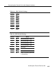
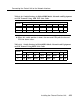
Table 43. SW1 Default Settings
Position
Status
1
up
2
down
3
down
4
down
5
down
6
down
7
down
8
down
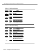
Table 44. SW2 Default Settings
Position
1
Status
Effect
up
BER threshold is 10-6
2
down BER threshold is 10-6
3
up
BER threshold is 10-6
4
up
BER threshold is 10-6
5
up
not used
6
up
not used
7
up
not used
8
up
Alarm LED/relay operation
is momentary.
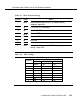
Installing the Channel Service Unit
4-19