
Instruction manual


Connecting the Control Unit to the Network Interface
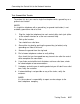
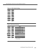
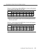
Table 4-7. SW6 Default Settings
Position
Status
1
down
2
up
3
4
5
6
7
8
up
down
Effect
send received signal to DTE or network during
Ioopback operation
DTE B8ZS is not decoded.
Network B8ZS is not decoded.
Network ESF
down
default to DIP switch configuration upon power-up
up
up
down
not used
not used
loop network signal back (ESS Ioopback) to network
during keep-alive
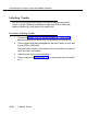
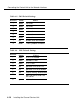
Table 4-8. SW7 Settings
Status
Position
0-150 ft 150-450 ft 450-655 ft
1
down
up
up
2
up
down
up
3
up
up
up
4
up
down
up
5
up
up
down
6
up
down
up
7
up
up
down
8
up up
up
Installing the Channel Service Unit
4-21