
Instruction manual


Connecting the Control Unit to the Network Interface
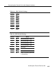
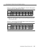
Table 4-10. Switch Settings in Hybrid/PBX Mode: Network and Equipment
are ESF Framed Using AMI ZCS Line Code
Switch
5
6
Position
1
2
3 4
5
6
7
8
up
down down
up
up
down
✱
up
up up
up
down
down
up
up up
✱
When this switch position is down, the near-end CSU polls the far-end
CSU for alarm status.
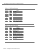
Table 4-11. Switch Settings in Hybrid/PBX Mode: Network and Equipment
are ESF Framed Using B8ZS Line Code
Switch
Position
1
2
3
4
5
6
7
8
5
up
up up
down
down
down
up
up
6
up
down down
down
down
up
up
up
Installing the Channel Service Unit
4-23