
Instruction manual
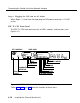
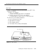

Connecting the Control Unit to the Network Interface
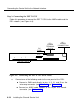
b. Connect the other end of the cord to the 100D module.
c. Connect the network interface cord to the CSU in one of the following
ways:
■ directly to pins 8,10, 26, and 28 on the wire-wrap connector
(see Table 4-15)
■
with a special cable adapter to the NET 15-pin male connector
(see Table 4-17)
NOTE:
See the ESF T1 documentation for the name of this cable
adapter.
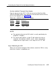
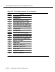
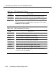
Table 4-14. 100D Module Pin Assignments
Pin No.
Designation
Signal
1 T1
RCV (tip)
2
R1
RCV (ring)
4
R
XMT (ring)
5
T
XMT (tip)
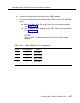
Installing the Channel Service Unit
4-27