
Instruction manual
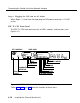

Connecting the Control Unit to the Network Interface
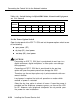
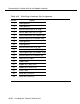
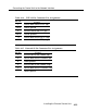
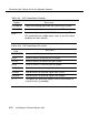
Table 4-15. Wire-Wrap Connector Pin Assignments
Pin No.
1
Signal
shield ground
2
shield ground
3
5
transmit data to the DTE (ring)
receive data from the DTE (tip)
8
receive data from the network (tip)
10
19
20
21
23
26
28
transmit data to the network (ring)
shield ground
shield ground
transmit data to the DTE (tip)
receive data from the DTE (ring)
receive data from the network (ring)
transmit data to the network (tip)
30
external ACO input
31
audible com
32
33
34
35
36
audible N/C (with ACO)
audible N/O (with ACO)
visual com
visual N/C (no ACO)
visual N/O (no ACO)
4-28
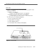
Installing the Channel Service Unit