
Instruction manual
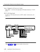

Connecting the Control Unit to the Network Interface
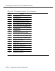
Table 4-16. DTE 15-Pin Connector Pin Assignments
Pin No.
1
2 or 8
3
4 or 15
9
11
Signal
receive data from the DTE (tip)
shield ground
transmit data to the DTE (tip)
shield ground
receive data from the DTE (ring)
transmit data to the DTE (ring)
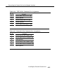
Table 4-17. Network 15-Pin Connector Pin Assignments
Pin No.
1
3
Signal
transmit data to the network (tip)
receive data from the network (tip)
8
9
11
15
shield ground
transmit data to the network (ring)
receive data from the network (ring)
shield ground
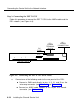
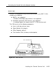
Installing the Channel Service Unit
4-29