
Instruction manual

Connecting the Control Unit to the Network Interface
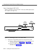
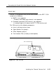
Step 4: Plugging the CSU into an AC Outlet
When Steps 1, 2, and 3 are finished, plug the CSU power cord into a 117-VAC
outlet.
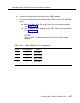
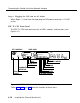
ESF T1 CSU Front Panel
The ESF T1 CSU front panel consists of LEDs, controls, and test jacks (see
Figure 4-7).
DTE LOOPBACK
SEND CODE
ESF T1 CSU
AT&T
AOO
UP
UP/DN
Eq Eq SM SM
O
IN OUT MON MON IN OUT
-1 +1
O
FRAME
LOSS
LOW DENS
LOOPED
ALARM
LOCAL
POWER
DIAGNOSTIC
INTERFACE
NEAR END LOOPED
BPV
CRC ERROR
FRAME LOSS
PULSES
CRITICAL POWER
FAR END LOOPED
Figure 4-7. ESF T1 CSU Front Panel
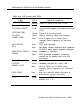
Tables 4-18, 4-19, and 4-20 show the functions of these items.
4-30 Installing the Channel Service Unit