
Instruction manual

fg
Connecting the Control Unit to the Network Interface
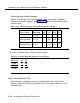
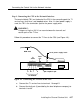
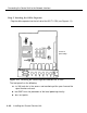
Step 5: Inserting the Office Repeater
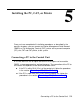
Plug the office repeater into the left slot of the 551 T1 CSU (see Figure 4-11):
Screws for
option settings
Figure 4-11. Inserting the Office Repeater into the 551 Tl CSU
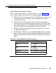
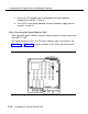
The front panel has the following:
■ six 310 jacks for in-line access and monitoring of the span line and the
signal monitor unit card
■ two GMT fuses for protection of the local powering circuitry
■ four test points
4-40
Installing the Channel Service Unit