
Instruction manual


Installing the Control Unit
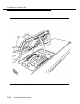
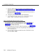
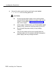
HDR4
SHUNT
HDR3
Do not touch
HDR3
Figure 2-12. Modifying the Processor Board for Key Mode
d.
e.
f.
g.
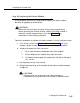
on the exposed portion of the processor board, find the header
marked
HDR4;
it is in the upper-left area.
A shunt is attached to one of the pins on the HDR4 header.
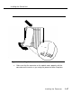
Remove the shunt from the single header pin; then reinsert it so that it
covers both pins on the header.
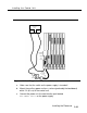
Take the
KF
label from the Jack Numbering Labels Sheet that is
packed with the feature module; fasten it to the wire manager at the
base of the module.
2-42
Installing the Processor