
Instruction manual


Installing the Control Unit
e. Check the HDR4 header on the processor circuit board for proper
mode operation (see “Step 1: Modifying the Processor for Key Mode”
earlier in this chapter).
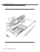
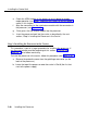
f. Align the connectors on the new feature module with the connectors in
the processor (see Figure 2-13).
g. Firmly press the new feature module into the processor.
h. Insert the processor back into the carrier as described in
section, “Step 3: Installing the Processor in the Carrier.”
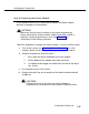
Step 3: Installing the Processor in the Carrier
the next
This procedure is part of a larger procedure for installing the processor. If
you have not already read the beginning of this section, “Installing the
Processor,” do so before continuing.
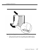
To install the processor in the carrier, follow this procedure (see Figure 2-14).
a. Remove the protective cover from the gold-finger connector (on the
back of the processor).
b. Lower the top of the processor onto the carrier in Slot 0 (the first slot
next to the power supply).
2-46
Installing the Processor