
Instruction manual


Installing the Control Unit
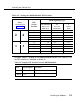
Table 2-4. Setting the 400EM Module DIP Switches
E&M Signaling Type
Ports
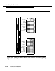
(As numbered in
Figure 2-15)
DIP
Switch
Position
1S (Default)
5
Simplex
Mode
1C
Protected
E&M Mode
Unprotected -
E&M Mode
ON
1
OFF NA
2
ON OFF
NA
2 4
3
OFF
OFF
OFF ON
4
OFF
ON
5
OFF
OFF ON
6
7
ON
ON
OFF
NA
OFF
NA
1 3
8
OFF
OFF ON
9
OFF
OFF
OFF
ON
10
OFF ON
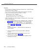
Example: If ports 1 through 4 are programmed per column 2 of Table 2-5, set
the DIP switches as indicated in column 3:
Table 2-5. Sample DIP Switches for the 400EM Module
Ports
E&M Signal
Switches
1 and 2
1C
Set all switches to
OFF
3 and 4
1S
Default: no action required
Installing the Modules
2-55