AT&T PARTNER™ Plus Communications System Installation and Programming Guide
AT&T 999-506-141 Issue 2 October 1990 Copyright © 1990 AT&T All Rights Reserved Printed in U.S.A. Notice Every effort was made to ensure that the information in this document was complete and accurate at the time of printing. However, information is subject to change. Federal Communications Commission (FCC) Information For important FCC interference, registration, and repair information, see appendix C of this document. Trademarks PARTNER is a trademark of AT&T.
Contents About This Guide 1 System Components and Specifications ■ ■ ■ 2 Hardware An Example System Setup Specifications Installing the Hardware General Guidelines Installing the Control Unit Installing Telephones and Other Equipment Removing/Replacing Modules 3 2-1 2-2 2-4 2-6 System Programming ■ ■ ■ 4 1-1 1-2 1-4 Overview General Instructions Programming Procedures 3-1 3-3 3-4 Centralized Telephone Programming ■ ■ Overview Programming Procedures 4-1 4-3
A Programming for Operation Behind PBX or Centrex B Dialing Restrictions Summary C FCC Information IN Index
About This Guide The PARTNERTM Plus Communications System is friendly and easy-to-use. Its digital technology provides features that give busy, growing businesses an advantage in today’s marketplace. The system is easy to install and program. As your business grows, you can expand the system and reprogram it with little effort and disruption. This Installation and Programming Guide is a comprehensive guide to setting up the PARTNER Plus system.
Reference Materials The following materials are available to help you install, program, and use the PARTNER Plus system (the order numbers are in parentheses): System Planner provides the forms needed to plan and record how your system and telephones are to be programmed. If you need a System Planner, contact your AT&T customer service representative or authorized dealer. Installation and Programming Guide (999-506-141) provides instructions for installing the hardware and programming the system.
System Components and Specifications 1 1-i
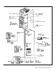
Hardware The PARTNER Plus system’s modular hardware design makes it easy to install and expand. The main system component is the control unit, to which you connect telephones and other equipment. Control Unit The control unit includes: ■ Processor Module. The processor module contains the software that controls the system’s features. It also has two jacks for connecting a loudspeaker paging system and an audio source for music on hold. ■ 206 Modules.
An Example System Setup This PARTNER Plus System has 4 outside lines and 8 extensions connected to a variety of PARTNER phones and other equipment. The boldface numbers refer to the following list which gives a brief description of the system’s hardware components. Control Unit. The heart of the PARTNER Plus system, the control unit consists of a backplane, cover (not shown), one processor module, plus up to four 206 modules.
System Components and Specifications 1-3
Specifications A Table 1-1 Technical and Environmental Specifications Capacities System 206 Module 8 outside lines via line jacks on four 206 modules 24 extensions via extension jacks on four 206 modules 1 loudspeaker paging system via PAGE jack on processor module 1 audio source via MUSIC ON HOLD jack on processor module 2 doorphones, using 2 extension jacks ● ● ● ● ● Dimensions ● 4.0 lbs or 8.8 kgs 4.5 Ibs or 9.9 kgs 5.5 Ibs or 12.2 kgs 1.8 lbs or 4.0 kgs 2.0 Ibs or 4.4 kgs 2.1 Ibs or 4.
Table 1-1 Technical and Environmental Specifications (cont.) Electrical Requirements ● ● ● Wiring ● ● ● ● Local Phone Company Information ● ● ● ● ● 90-130 VAC, 50-60 Hz, 3-prong outlet separate ground, separately fused at 15 amps Outlet must not be controlled by an on/off switch Grounding to comply with Underwriters Laboratories (UL) 1459: A.
Installing the Hardware 2 2-i
General Guidelines Instructions for installing the control unit, telephones, and other equipment are on the following pages (figures 2-1 to 2-3). Before you begin, please note the following guidelines: Using the System Planner is essential for knowing where phones and other equipment are to be installed, and how the system and phones are to be programmed. Install the control unit so that it meets the environmental and electrical requirements listed on p. 1-4.
Installing the Control Unit CAUTION: To prevent electrostatic discharge, overheating, or other damage, environmental and electrical conditions must meet the specifications on p. 1-4. MOUNT THE BACKPLANE ON A WALL Hold the backplane in place on the wall. Using the four screw keyholes in the backplane as a template, mark the screw locations on the wall. Start the four #12 screws, Ieaving thereabout 1/4” out from the wall.
Installing the Hardware 2-3
Installing Telephones and Other Equipment CAUTION: PARTNER phones must be connected with a 2-pair telephone wire. Other equipment must be connected with a 1-pair mounting cord (AT&T D2R mounting cords recommended). DESK MOUNTING A PARTNER PHONE Plug one end of the handset cord into the jack on the handset. Plug the other end of the cord into the small jack on the left side of the base. Plug one end of the telephone mounting cord into the big jack on the base of the phone.
WARNING: Do not attempt to unscrew the base from the phone. To do so will expose you to a risk of electrical shock. Test a telephone by lifting the handset. You should hear a dial tone, indicating a good connection on the line. If you don’t, see chapter 8, in the System Manager’s Guide, (“Phone Has Lights but No Dial Tone”). Reverse the plastic hook that sits in the earpiece part of the handset cradle. If you install a fax machine and want to assign a Fax Management button, see p.
Removing/Replacing Modules Removing a Module To remove a processor or 206 module: 1. Disconnect the AC power cord from the wall outlet. 2. Remove the control unit cover by sliding it directly off the backplane. 3. Grasp the front top of the module with one hand while holding down the locking tab at the base of the module with the other hand. With the locking tab down, put one finger of the same hand in the wire bracket on the bottom front of the module.
System Programming 3 3-i
Alphabetic List of Procedures Abbreviated Ringing Allowed List Assignment Allowed Phone Number Lists Automatic Privacy Calling Group Extensions Copy Settings Dial Mode Disallowed List Assignment Disallowed Phone Number Lists Display Language Doorphone 1 Extension Doorphone 2 Extension Doorphone Alert Extensions Emergency Phone Number List Fax Machine Extensions Hold Disconnect Time Hotline Line Assignment Line Type Line Use Restriction Music On Hold Night Service Button Night Service Group Number of Lines O
Overview This chapter provides instructions for programming your system. Your PARTNER Plus system was programmed at the factory so that it works when installed. However, the needs of your business may require that you change some or all of the factory settings. System programming allows you to change these factory settings. For example, each year when the time changes from Standard Time to Daylight Savings Time, you will want to change the system time. This change is easy to make through system programming.
Figure 3-1 Programming Overlay 3-2 System Programming
General Instructions Programming the PARTNER Plus system requires no complicated steps or intensive training. By following the detailed instructions given in the rest of this chapter, you can quickly change system settings. As you become familiar with programming, use the Programming Quick Reference on the inside back cover of this guide for procedure codes and settings.
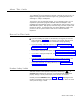
Programming Procedures System Date Code: #101 If your system has been previously programmed, the displays may differ. Description: The month, day, and year that appears on PARTNER display phones Valid Entries: Any date Programming Steps: 1. Press [ Feature ] [ 0 ] [ 0 ] [ System Program ] [ System Program ] [ # ] [ 1 ] [ 0 ] [ 1 ] . display reads: System Date Data 010100 2. Enter today’s date in the form MMDDYY, using leading zeroes for all single-digit months and dates.
System Time Code: #103 Description: The time, in 24-hour military-style notation Valid Entries: Any time Even though you enter the time in 24-hour notation, it appears on display phones as a.m. and p.m. after you program it. Programming Notes: Enter the time in 24-hour notation, commonly known as military time. In this scheme, the hours of the day are 0000 (12 midnight) to 2359 (11:59 p.m.). Since each time must have four digits, use leading zeroes when necessary. For example, to set the time to 9:00 a.
Transfer Return Rings Code: #105 Description: Defines the number of times an extension should ring with a transferred call before the call returns to the originating extension. Valid Entries: 0 (transferred calls not returned to originating extension) 1 through 9 ✓4 Considerations: If you have a fax machine or an answering machine connected to the system, set this number greater than the number of rings these devices wait before answering.
Recall Timer Duration Code: #107 Description: Changes the length of the timed signal (a switchhook flash) executed by the Recall feature (p. 4-8) and by the Recall function of speed dialing (p. 3-36). Recall sends this timed signal over the phone line to the local telephone company or PBX/Centrex to which the system is connected. Typically you use the Recall feature to access PBX or Centrex features such as Call Waiting.
Rotary Dialing Time out Code: #108 Description: If you have any rotary lines and are having trouble calling out on standard touch-tone phones, use this procedure to change the length of the Rotary Dialing Timeout. For example, if users dial slowly and calls are not completed or are connected to wrong numbers, lengthen the timeout. Do not change this setting unless the system is experiencing problems.
Dial Mode Code: #201 Description: Identifies each outside line as either touch-tone or rotary. Valid Entries: ✓ 1 = Touch-tone line 2 = Rotary line Considerations: If you are using touch-tone phones on rotary lines, you may need to adjust the Rotary Dialing Timeout (#108). Programming Steps: 1. Press [ Feature ] [ 0 ] [ 0 ] [ System Program ] [ System Program ] [ # ] [ 2 ] [ 0 ] [ 1 ] . The display reads: Dial Mode Line: 2. Enter the first line to be programmed.
Line Type Code: #202 Description: Identifies each outside line as being connected to the local telephone company or to a PBX or a Centrex system. See appendix A for more information on programming for PBX or Centrex. Valid Entries: ✓ 1 = CO (local telephone company line) 2 = PBX or Centrex line Considerations: ■ ■ If any lines are connected to a PBX or a Centrex system, use procedure #106, PBX Dial-Out Code, to identify the PBX/Centrex dial-out code.
Hold Disconnect Time Code: #203 Description: When a caller on hold hangs up, the local telephone company may send a special signal to the PARTNER Plus system to free the line. There are two possible signals: a long signal (450 milliseconds) used by most telephone companies, or a short signal (50 milliseconds) used by a few telephone companies. The length of the signal is called the hold disconnect time.
Line Assignment Code: #301 Description: Use this procedure to change the line assignments on specific extensions. These changes include adding lines, deleting lines, and setting the order of the lines on a PARTNER phone’s line buttons. Valid Entries: ✓ 1 = Assigned 2 = Not assigned Hotline and doorphone extensions should not have outside lines assigned to them, to prevent calls from being made or received on them.
Line Use Restriction Restricting the use of a line is the most extreme way to restrict dialing on the PARTNER Plus system. For example, an extension with a the set to "in only” or "no access,” cannot select the line to dial out, even emergency numbers. There are other, less extreme ways to restrict dialing. See appendix B for a summary of dialing restrictions. Code: #302 Description: Use this procedure to restrict extensions from receiving and/or making outside calls on specific lines.
Display Language Code: #303 Description: Sets the language on the display of a PARTNER display phone. The language is set for each extension, so phones on the same PARTNER system can display different languages. Valid Entries: ✓ 1 = English 2 = Spanish 3 = French If you change the language for extension 10, the display messages immediately start appearing in the new language. Programming Steps: 1. Press [ Feature ] [ 0 ] [ 0 ] [ System Program ] [ System Program ] [ # ] [ 3 ] [ 0 ] [ 3 ].
Automatic Privacy Code: #304 Description: Automatically prevents users with the same lines from joining telephone conversations on a specific extension. This feature is typically used for extensions connected to fax machines and modems, which make and receive data calls that should not be interrupted. Valid Entries: 1 = Assigned to extension ✓ 2 = Not assigned Considerations: A user can override Automatic Privacy with the Privacy feature (p. 4-l0). Programming Steps: 1.
Abbreviated Ringing Receptionists, and others who handle many calls quickly, often turn Abbreviated Ringing off, so they have an audible reminder of incoming calls. Code: #305 Description: Use this procedure to turn Abbreviated Ringing on or off. When a user is on a call and Abbreviated Ringing is on (the factory setting), an incoming call rings only once. The light next to the line button flashes until the call is answered or the caller hangs up.
Copy Settings Code: #399 Description: Copies the following settings from any extension to any other extension: #408 Allowed List Assignment #301 Line Assignment #302 Line Use Restriction #501 Pickup Group Extensions #303 Display Language #502 Calling Group Extensions #304 Automatic Privacy #504 Night Service Group #305 Abbreviated Ringing #601 Fax Machine Extensions #401 Outgoing Call Restrictions Automatic Line Selection (p. 4-3) #405 Disallowed List Assignment Line Ringing Options (p.
Outgoing Call Restrictions While procedures that restrict dialing are very effective, absolute protection against misuse cannot be guaranteed. PARTNER phones give you more protection against such misuse than standard phones. Therefore, we strongly recommend that you install PARTNER phones where restricting phone use is important. See appendix B for a complete summary of dialing restrictions. Code: #401 Description: Restricts the types of calls an extension can make.
Toll Call Prefix Code: #402 Description: Phone companies recognize long distance calls in either of two ways: a telephone number preceded by 0 or 1 plus an area code or a tele- phone number preceded only by an area code. Use this procedure to tell the PARTNER Plus system which method your phone company uses. Valid Entries: ✓ 1 = 0 or 1 plus the area code 2 = Area code only (0 or 1 not necessary) Programming Steps: 1.
Disallowed Phone Number Lists See appendix B for a summary of dialing restrictions. Code: #404 Description: Specifies telephone numbers that users cannot dial. For example, you may want to prevent calls to a specific telephone number or to categories of numbers such as calls to 976 numbers. Use this procedure to create up to four lists of up to 10 telephone numbers each. Then use procedure #405, Disallowed List Assignment, to assign the lists to specific extensions.
Programming Notes: To program telephone numbers, dial the number as you would normally. You can also use the "wildcard” character to stand for any digit in a phone number. For example, if you want to prevent users from making calls to area codes 202 and 212, you could enter each area code separately or combine them in one entry using the wildcard to stand for the middle digit. Using the wildcard, you would press [ 2 ] [ Wild ] [ 2 ] .
Disallowed List Assignment Code: #405 Description: After creating Disallowed Phone Number Lists (#404), use this procedure to assign them to specific extensions. For example, you can assign list 1 to extensions 27 and 28, and list 2 to extension 28 only. Valid Entries: 1 = Assigned to extension ✓ 2 = Not assigned to extension Programming Steps: 1. Press [ Feature ] [ 0 ] [ 0 ] [ System Program ] [ System Program ] [ # ] [ 4 ] [ 0 ] [ 5 ] . The display reads: DisallowTo Extension: 2.
Emergency Phone Number List See appendix B for a summary of dialing restrictions. Code: #406 Description: Specifies emergency telephone numbers, such as “911,” that can be dialed from any extension regardless of other dialing restrictions, except Line Use Restriction (#302). Valid Entries: 10 telephone numbers, 1 to 12 digits each Programming Notes: The emergency list can contain specific telephone numbers or categories of telephone numbers.
Allowed Phone Number Lists See appendix B for a summary of dialing restrictions. Code: #407 Description: Specifies telephone numbers that users can dial regardless of other dialing restrictions. For example, even though you restricted all “976” dialing through Disallowed Phone Number Lists (#404), you can permit calls to the 976 weather number by entering that number in an allowed list. Using this procedure, you can create up to four lists of up to 10 telephone numbers each.
Pickup Group Extensions Code: #501 Description: Identifies the extensions in the Pickup Group-the group of extensions whose outside calls can be answered by any extension on the system. When an outside call rings at an extension in the Pickup Group, any other extension on the system can answer the ringing line by pressing [ Intercom ] [ 6 ] [ 6 ] . The system automatically connects the call to the extension, even though the extension may not be in the group and may not have that line assigned to it.
Calling Group Extensions Code: #502 Description: Identifies the extensions in the Calling Group-the group of extensions that can be called at the same time. Any user on the system can ring all the phones in the Calling Group by dialing [ Intercom ]. Users can also voice signal the phones in the Calling Group by dialing [ Intercom ] [ * ] [ 7 ] [ 1 ]. This feature is useful for conversing with a group of users such as a sales pool or customer service representatives.
Night Service Button Code: #503 Description: To use the Night Service feature, you must program it onto the PARTNER display phone at extension 10. This procedure automatically assigns Night Service to the second programmable feature button with lights: Night Service is useful if you want all phones to ring after hours. For example, the Shipping Department does not answer calls during the day, but after hours you want them to answer incoming calls.
Night Service Group Code: #504 Description: Identifies the extensions in the Night Service Group. When Night Service is on and a call comes in, all extensions in the Night Service Group ring immediately. In addition, restricted Night Service (when the system has a password) limits the Night Service Group extensions to dialing only numbers on the Emergency Phone Number List (#403) and Marked System Speed Dial Numbers (p. 3-34).
Fax Machine Extensions Code: #601 Description: If you have a fax machine connected to the system and want to monitor its status with a Fax Management button (see the System Manager’s Guide, chapter 7), use this procedure to identify the fax extension. Valid Entries: 1 = Extension assigned ✓ 2 = Extension not assigned Considerations: To prevent other extensions from interrupting a fax call, program the fax extension for Automatic Privacy (#304).
Music On Hold Code: #602 Description: Activates or deactivates the Music-on-Hold jack on the processor module. To provide music or taped messages to callers on hold, the Music-onHold jack must be active and an audio source attached to the jack. Valid Entries: ✓ 1 = Active 2 = Not active Considerations: If no audio source is attached to the system, we recommend changing the setting to “not active.
Hotline Code: #603 Description: Identifies the “hotline” extension and the extension it automatically rings (the “alert” extension). When someone lifts the handset of the hotline telephone, the alert extension rings. You can set up several hotline and alert extension pairs. The alert extension can be the same or different for one or more hotline extensions.
Doorphone 1 Extension Code: #604 A doorphone consists of a speaker and a button. It is usually placed near an entrance for screening visitors. Description: You can connect up to two doorphones to the PARTNER Plus system. Each doorphone can ring up to five other “alert” extensions. Use this procedure to identify the extension to which the first doorphone is connected. Use procedure #605 to identify the second doorphone extension. Use procedure #606 to assign the alert extensions for both doorphones.
Doorphone Alert Extensions Code: #606 Description: Identifies the extension or extensions that ring when someone presses the button on a doorphone. Each doorphone can have up to five alert extensions. The doorphones can have five individual alert extensions or they can share alert extensions. Use procedures #604 and #605 (Doorphone 1 and Doorphone 2 Extensions) to assign doorphone extensions.
System Reset— Programming Saved Code: #728 Description: Resets the system while retaining the currently programmed settings. Reset the system only when it fails to function correctly after a power failure or down period. Considerations: ■ The system reset begins immediately and takes only a few seconds. ■ You cannot interrupt the reset process. You cannot use any telephones in the system during the reset process. ■ Resetting the system disconnects all active calls. Programming Steps: 1.
Programming Steps: 1. Press [ Feature ] [ 0 ] [ 0 ] . The display reads: PROGRAM EXT 10 2. Enter the 2-digit code you want to assign the phone number by pressing [ Feature ] and 2 digits between 20 and 79. For example, to assign code 20, press [ Feature ] [ 2 ] [ 0 ] . If a number is already assigned to the code, it appears in the display. If no number is assigned to the code, the display reads: Blank 3. Enter the phone number.
Table 3-1 Special Dialing Functions Function Button Display Description and Example Pause [ Hold ] P Inserts a 1.5-second pause in the dialing sequence to wait for a response, such as a dial tone or computer voice message. Example: To call an answering machine at 555-0529, wait 4.5 seconds, then dial 321 to retrieve messages, enter [ 5 ] [ 5 ] [ 5 ] [ 0 ] [5 ] [ 2 ] [ 9 ] [ Hold ] [ Hold ] [ 3 ] [ 2 ] [ 1 ].
Centralized Telephone Programming 4 4-i
Alphabetic List of Procedures Auto Dial Numbers Automatic Line Selection Call Pickup Calling Group Conference Drop Do Not Disturb Exclusive Hold Last Number Redial Line Ringing Options Loudspeaker Paging Message Light Off Message Light On Personal Speed Dial Numbers Pickup Group Privacy Recall Save Number Redial Touch-Tone Enable 4-ii Centralized Telephone Programming 4-6 4-3 4-12 4-13 4-9 4-7 4-7 4-9 4-4 4-13 4-11 4-11 4-5 4-12 4-10 4-8 4-8 4-10
Overview PARTNER telephones are ready to use when installed. However, just as the system can be programmed to meet your business’s needs, the phones can be programmed to meet users’ needs. Individual users can program their own phones. In addition, you can program any phone on the system from extension 10. Programming from extension 10 is called centralized telephone programming, the topic of this chapter. Centralized telephone programming provides an easy way to customize phones for users.
PARTNER Display and PARTNER 12-Button Phones PARTNER 6-Button Phone Figure 4-1 Buttons and Labeling Sheets for PARTNER Phones 4-2 Centralized Telephone Programming
Programming Procedures Automatic Line Selection For example, lines 1 and 2 are assigned to an extension. If line 1 is free, the system connects the user to that line. If line 1 is busy but line 2 is free, the system connects the user to line 2. If both lines are busy the system connects tie user to an intercom line (if available).
Line Ringing Options Description: Each outside line assigned to an extension can ring immediately, be delayed 20 seconds before ringing, or not ring at all. “Delayed ring” is useful for backup coverage on shared lines, such as for secretaries who cover each otther's lines. “No ring” is useful for phones with no regular users, such as in conference rooms. Valid Entries: ✓ Immediate ring Delayed ring No ring Programming Steps: 1.
Personal Speed Dial Numbers Description: You can program up to 20 frequently dialed numbers for each extension. The user can then dial these numbers by pressing [ Feature ] and the 2-digit code you assign the number during programming. Personal Speed Dial numbers do not override other restrictions assigned to an extension.
Auto Dial Numbers Programming an Auto Dial extension provides one-touch transfer of calls to that extension, and one-touch conferencing. Programming an Auto Dial extension number onto a button with lights shows the calling activity at the extension. Description: Use this procedure to program outside telephone numbers or other extension numbers onto buttons for one-touch dialing. Auto Dial numbers do not override the dialing restrictions for the extension.
Do Not Disturb Feature Code: 01 Description: Prevents a telephone from ringing. When Do Not Disturb is on, outside callers hear ringing while inside callers hear a busy signal. By programming this feature on a button, the user can turn Do Not Disturb on and off with one touch. You cannot use this feature unless you program it on a button with lights. Programming Notes: The Do Not Disturb feature requires a programmable button with lights.
Recall Feature Code: 03 Description: Sends a timed switchhook flash over the telephone line. The user may need to send a recall signal to use certain Centrex or PBX features, such as Call Waiting. By programming this feature on a button, the user can send a recall signal with one touch. If users have problems with the recall signal, you may need to reset the Recall Timer Duration (#l07). Programming Steps: 1. Press [ Feature ] [ 0 ] [ 0 ] [ System Program ] [ System Program ] [ Central Tel Prog ].
Last Number Redial Feature Code: 05 Description: Redials the last outside number dialed at the extension (maximum 20 digits per phone number). By programming this feature on a button, the user can redial the number with one touch. System Speed Dial numbers cannot be saved for redialing. Programming Steps: 1. Press [ Feature ] [ 0 ] [ 0 ] [ System Program ] [ System Program ] [ Central Tel Prog ]. The display reads: CENTRAL TEL PROG Extension: 2.. Enter the extension to be programmed.
Privacy Feature Code: 07 Description: Prevents other users with the same line from joining telephone conversations. By programming this feature on a button, the user can turn Privacy on and off with one touch. Considerations: If an extension has Automatic Privacy (#304), the user can turn it off and on with Privacy. You cannot use this feature unless you program it on a button with lights. Programming Notes: Privacy requires a programmable button with lights.
Message Light On Feature Code: 09 Description: Alerts another extension that there is a message for it by turning on the Message light at that extension. By programming this feature on a button, the user can turn on the message light at a PARTNER phone by pressing the button and dialing the extension. Programming Steps: 1. Press [ Feature ] [ 0 ] [ 0 ] [ System Program ] [ System Program ] [ Central Tel Prog ]. The display reads: CENTRAL TEL PROG Extension: 2. Enter the extension to be programmed.
Call Pickup This feature is useful for oifficemates who agree to answer each other’s calls. Description: Enables the user to answer any call ringing on a specific extension. By programming this feature on a button, the user can pick up a call on that extension with one touch. Programming Steps 1. Press [ Feature ] [ 0 ] [ 0 ] [ System Program ] [ System Program ] [ Central Tel Prog ] . The display reads: CENTRAL TEL PROG Extension: 2. Enter the extension to be programmed.
Loudspeaker Paging Description: If the system has a loudspeaker paging system, this feature activates it. By programming this feature on a button, the user can activate the loudspeaker with one touch. Programming Steps: 1. Press [ Feature ] [ 0 ] [ 0 ] [ System Program ] [ System Program ] [ Central Tel Prog ]. The display reads: CENTRAL TEL PROG Extension: 2. Enter the extension to be programmed. For example, to program extension 28, press [ 2 ] [ 8 ] . The display reads: PROGRAM EXT 28 3.
Programming for Operation Behind PBX or Centrex If you are connecting your PARTNER Plus system to a PBX (Private Branch Exchange) or Centrex system, instead of directly to local telephone company lines, there are two ways to program the system. Your choice depends on what kinds of calls your users tend to make. If they make most of their calls to outside parties and/or to other extensions in the PARTNER Plus system, choose Programming Method A.
Considerations: ■ PBX or Centrex extension numbers cannot be used as System Speed Dial numbers, Personal Speed Dial numbers, or Auto Dial numbers. ■ Last Number Redial and Save Number Redial will not work properly when the “last” or “saved” number was a PBX or Centrex extension number. However, a user can dial a PBX or Centrex extension number directly. Programming Method B Use when most calls are made to PBX or Centrex extensions. 1. Follow steps 1 through 3 in “Programming Method A,” above. 2.
Dialing Restrictions Summary While procedures that restrict dialing are very effective, absolute protection against misuse cannot be guaranteed. PARTNER phones give more protection than standard phones. Therefore, we strongly recommend that you install PARTNER phones where restricting phone use is important. The PARTNER Plus system includes several ways to restrict dialing from individual extensions. This appendix discusses the dialing restrictions and ways to override the restrictions.
Outside Dialing Allowed When an extension is allowed access to an outside line, several dialing restrictions can apply. First, regardless of other restrictions, some types of calls are always allowed. Second, you can restrict dialing after normal business hours through Night Service. Finally, you can limit dialing through Allowed Phone Number Lists, Disallowed Phone Number Lists, and outgoing Call Restrictions.
■ #401—Outgoing Call Restrictions. Using this procedure, you set one of three dialing restrictions for each extension: ■ ■ ■ “No restriction” allows long distance, local, and inside calling. “Local only” allows local and inside calling only (make sure the Toll Call Prefix is set properly, #402). “Inside only” allows inside calls only. The Outgoing Call Restrictions apply to all lines assigned to that extension.
FCC Information Federal Communications Commission (FCC) Warning Statement This equipment has been tested and found to comply with the limits for a Class A digital device, pursuant to Part 15 of FCC rules. These limits are designed to provide reasonable protection against harmful interference when the equipment is operated in a commercial environment.
You must also notify your local telephone company if and when this equipment is permanently disconnected from the line(s). Repair Instructions: If you experience trouble because your equipment is malfunctioning, the FCC requires that the equipment not be used and that it be disconnected from the network until the problem has been corrected. Repairs to this equipment can only be made by the manufacturers, their authorized agents, or by others who may be authorized by the FCC.
Index D 206 module, 1-1, 1-2, 1-3 267F2 bridging adapter, 1-2, 1-3, 2-5 A Abbreviated Ringing (#305), 3-16 Adjustable stand, 2-4 Allowed List Assignment (#408), 3-24, B-2 Allowed Phone Number Lists (#407), 3-24, B-2 Audio source, installing, 2-2, 2-3 Auto Dial Numbers, 4-6 Auto intercom, see Auto Dial numbers Automatic Line Selection, 4-3 Automatic Privacy (#304), 3-15 Date, System (#101), 3-4 Day, System (#102), 3-4 Delayed ring, 4-4 Desk mounting a PARTNER phone, 2-4 Dial Mode (#201), 3-9 Dialing restri
Group, Calling, 3-26, 4-13 Group, Night Service, 3-28 Group, Pickup, 3-25, 4-12 Guidelines for installation, 2-1 H Hardware, 1-1 to 1-3 Hearing aid compatibility, C-2 Hold Disconnect Time (#203), 3-11 Hold, Exclusive, 4-7 Hotline (#603), 3-31 programming for, 2-1 standard phone used as, 2-1 I Immediate ring, 4-4 Industry-standard devices, 1-1, 1-2, 1-3 Installation, hardware 267F2 bridging adapter, 2-5 audio source, 2-2, 2-3 combination extension, 2-5 control unit, 2-2 to 2-3 guidelines for, 2-1 loudspeak
O One-touch transfer, see Auto Dial Numbers Outgoing Call Restrictions (#401 ), 3-18, B-3 Outside Conference restriction (#109), 3-8 Overlay, programming, 3-1 to 3-2 Redial, Last Number, 4-9 Redial, Save Number, 4-8 Removing modules, 2-6 Replacing modules, 2-6 Resetting the system, 3-34 Restrictions, dialing, B-1 to B-3 Restrictions, Outgoing Call (#401), 3-18, B-3 Ringer Equivalence Number (REN), 1-4, 1-5 Ringing, Abbreviated (#305), 3-16 Rings, Transfer Return (#105), 3-6 Rotary Dialing Timeout (#108), 3
Telephones installation, 2-4 to 2-5 programming centrally, 4-1 to 4-13 Time, System (#103), 3-5 Toll Call Prefix (#402), 3-19 Touch-Tone Enable programming feature on a button, 4-10 programming function in phone number, 3-36 Touch-tone lines, 3-9 Transfer Return Rings (#105), 3-6 W Wall mounting a PARTNER phone, 2-5 Weights, 1-4 Wires, connecting, 2-2 to 2-3 Wiring specifications, 1-5, 2-1 IN-iv
Programming Quick Reference Centralized Telephone Programming and System Speed Dial Numbers ■ Perform these procedures at Extension 10, using a PARTNER display phone (MLS-12D) ■ Place the Programming Overlay on the phone's dial pad. SYSTEM SPEED DIAL NUMBERS (p.
SYSTEM PROGRAMMING TO ENTER PROGRAM MODE Press [ Feature ] [ 0 ] [ 0 ] [ System Program ] [ System Program ] TO CYCLE THROUGH THE PROCEDURES Press [ Next Proc ] or [ Prev Proc ] TO GO TO A PARTICULAR PROCEDURE DIAL ITS 3-DIGIT CODE Example: [ # ] [ 1 ] [ 0 ] [ 1 ] TO RETURN DATA TO FACTORY SETTlNG: Press [ Remove ] TO LEAVE SYSTEM PROGRAM MODE: Press [ Feature ] [ 0 ] [ 0 ] I ✓ = Factory Setting SYSTEM DATE (p. 3-4) DIAL #101 DIAL the date inMMDDY form SYSTEM DAY (p.
SYSTEM RESET- PROGRAMMING SAVED (p. 3-34) DIAL #728 CAUTION: Disconnects active calls. RESTRICTIONS GROUPS OPTIONAL EQUIPMENT OUTGOING CALL RESTRlCTI0NS (p. 3-18) DIAL #401 PICKUP GROUP EXTENSIONS (p. 325) DIAL #501 FAX MACHINE EXTENSIONS* (pp.
Issue 2, October 1990 999-506-141 Comcode 106430184 Graphics © AT&T 1988