463-248-201 Issue 1 3/1/93 PagePac Plus Controller Installation and Use
Copyright 1993 AT&T All Rights Reserved Written/Printed in U.S.A. AT&T 463-248-201 011722051-000 Issue 1, March 1993 Notice Every effort was made to ensure that the information in this guide was complete and accurate at the time of printing. However, information is subject to change. Federal Communications Commission (FCC) and Canadian Dept.
Contents 1. Overview ■ ■ ■ ■ ■ ■ ■ ■ ■ ■ ■ ■ 2.
3. Installing the Hardware ■ ■ ■ ■ ■ ■ ■ ■ ■ ■ ■ ■ ■ 4.
Tables 1. 1-1 Overview 1-1. PagePac Plus Connectivity Chart 1-2. Controller Specifications 4. Maintenance and Customer Support 1-6 1-12 4-1 4-4 4-1.
Figures 1. Overview 1-1. 1-2. 2. 1-1 Hardware Installation Steps PagePac Plus System Components Hardware Configuration 2-1 2-1. Controller, Amplicenter, and Zone Expansion Unit Back Panels 3. 2-5 3-1 Installing the Hardware 3-1. 3-2. 3-3. 3-4. 3-5. 3-6. 3-7.
Overview 1 Overview 1-1
“This page intentionally left blank”
The following subsections give a summary of the PagePac Plus controller features, system components, and auxiliary equipment. About This Guide The PagePac Plus Paging Controller Installation and Use Guide explains the features of the PagePac Plus Controller, how to install and configure the controller, installation of the PagePac Plus amplicenter, and interface to communication system and other auxiliary equipment. For programming instructions, refer to the PagePac Plus Programming and Operation Guide.
Installation Steps NOTE: The numbers in these steps match the numbers in figure 1-1. 1. Determine PagePac Plus features to be used in the facility. Refer to the Zone Map and Zone Configuration Tables filled out in the Programmer’s Guide. 2. Verify Zone Map information matches facility wiring diagram. 3. Pull cables. 4. Mount the PagePac Plus components [Amplicenter, Controller and Zone Expansion Unit(s)], to either the wall, cabinet or a rack. 5.
Figure 1-1.
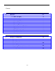
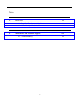
Connectivity Chart The Connectivity chart gives the trunk interface requirements for the host systems listed. This information is then used to set the telephone mode function switch on the PagePac Plus Controller. Table 1-1. PagePac Plus Connectivity Chart System 2000 Merlin Plus Mode C.O. Line C.O. Line Page Port Loop Start Yes Yes Note 1 — — — — — — — Ground Start Dry Loop (Hi Z) Dry Loop (600Ω) — — Spirit 308/616 Merlin 206/820 Merlin 1030/3070 C.O. Line Page Module C.O.
Table 1-1. PagePac Plus Connectivity Chart (continuation Page 1) System 25 Mode C.O. Line Analog Station System 85/G2 System 75/G1/G3I Definity Analog Station Aux. Port C.O. Line Analog Station Aux. Port C.O. Line — Yes — Aux. Port Loop Start Yes — — Yes — Ground Start Yes — — Yes — — Yes — — — — — — — — — — Yes Note 2 Dry Loop (Hi Z) Dry Loop (600 Ω) — — — — Yes Note 2 — — Yes Note 2 Horizon Comkey 416, 718 1434 and 2152 — — Dimension Mode C.O.
Product Safety Labels This guide contains several product safety labels, identified by a CAUTION - Indicates the presence of a hazard that will or can cause minor personal injury or property damage if the hazard is not avoided. WARNING - Indicates the presence of a hazard that can cause severe or fatal personal injury if the hazard is not avoided. Carefully read the WARNING label in section 2, Installation.
Shipping Container Contents The following items should be found in the PagePac Plus Controller shipping container. If something is missing, notify your local dealer. ■ Controller unit, including plastic, snap on cover. ■ Mounting hardware (screws and brackets) ■ Cables, preterminated, 8-pin modular (18“ long) ■ Cord, preterminated, RJ11 (18“ long) ■ Programming Guide ■ This Installation Guide Ordering Information Equipment is available from many AT&T sources.
Features and Capabilities The following list provides an overview of the features of the PagePac Plus system, illustrated in figure 1-1, along with additional application capabilities. NOTE: The Programming and Operation Guide details the features of the controller. Also, refer to the PagePac Plus Amplicenter and Zone Expansion Unit Service Manuals for specific information on those products. ■ Controller—Connects up to 8 zones and controls entire system.
Figure 1-2.
Specifications Table 1-2. Controller Specifications Capacities Dimensions and Weights ■ ■ The Controller connects up to 8 zones of audio output (including talkback) and contact closure inputs or outputs. 3-1/2’’ high x 19“ wide x 4-1/4” deep (assembled, approx.) 1 lb.
Hardware Configuration 2 Hardware Configuration 2-1
The PagePac Plus Controller can be installed to operate in several different ways: as a constant-voltage 70.7 volt distribution system, a multi-controller system, or a hybrid system. In any of the configurations, a PagePac Plus amplicenter D20, D100, or D300 is required and the interconnection between the control unit and the amplicenter must be made. See “Example System Setup.
Approvals Domestic and international approvals: ■ UL813, UL1459, paragraph 2.1, ■ FCC, Part 15, Class A (see Section 5) ■ FCC, Part 68, ■ CSA 225, ■ DOC. Controls, Indicators, Switches and Connectors LED Indicators The PagePac Plus Controller has three LED indicators that are useful for installation and troubleshooting purposes. Front panel— Single LED indicates the unit’s power status: solid green indicates the unit has power, and blinking green indicates that the unit is in reset mode.
Amplicenter: Control Unit: 1. AC Power in; 115VAC or 230VAC at 50 or 60 Hz 2. 0dBm out, control and audio for remote amplifier 3. DC Power and 70V audio out to controller 4. Bass (low frequency) control adjustment 5. 70V out; paging in (redundant to item #9); music in 6. Level adjustments: Music level, Music “ducking” (mute level), VOX sensitivity level 7. LEDs: green – page accessed, red – unbalanced output, red – overload, green – power on 8.
Figure 2-1.
Auxiliary Equipment 2-6 ■ Your PagePac Plus Controller is compatible with numerous peripheral products and speakers which can be utilized to meet your facility requirements ■ PagePac Plus Amplicenters D20, D100, and D300. P/N PEC 5328-20, -100, -300 ■ PagePac Plus Zone Expansion Units. Up to three maximum for 56 dial access zones.
Installing the Hardware 3 Installing the Hardware 3-1
3-2 Installing the Hardware
This section provides complete instructions for mounting the PagePac Plus controller on a wall or in a standard EIA 19“ cabinet or equipment rack. It also illustrates, in detail, all interface requirements to: telephone systems, music source, speakers, auxiliary equipment, and any control inputs or outputs. Switch settings are given for each zone application type. Important Safety Information Always follow these basic safety precautions when using the system: 1. Read and understand all instructions. 2.
Example System Setup 70 Volt Constant Voltage Distribution System This example system illustrated in figure 3-1 gives you a quick overview to a traditional 70 volt installation. This is the “traditional” paging system configuration. When the system is configured as a constant-voltage distribution system, the 70V amplicenter audio output is routed via the PagePac Plus controller to any zone that is optioned for audio.
Figure 3-1.
Figure 3-2.
Figure 3-3.
Mounting PagePac Plus Components The PagePac Plus components consist of the ■ Controller unit, ■ Amplicenter, and ■ Zone Expansion Unit(s), optional All PagePac Plus components must be securely wall mounted or installed in a standard 19“ EIA cabinet or equipment rack (Mounting hardware provided for rack mounting). Figure 3-4 illustrates a wall mounted configuration. Figure 3-5 illustrates a rack mounted arrangement.
Figure 3-4.
Figure 3-5.
Zone Configurations With the Zone Map dial codes and configuration tables (from the Programming and Operation Guide) filled out, and the PagePac Plus amplicenter, controller, and optional zone expansion unit(s) mounted, installation of the cabling and interface to the units can proceed. Each zone controlled by the PagePac Plus can be used for a ■ ■ ■ speaker or doorphone paging zone a contact closure to control a remote device a signal (contact closure) input to the controller to activate an action (i.e.
Figure 3-6.
Contact Closure Zone Connections The contact closure input and output and signal zone connect to the controller and zone expansion units are same as with the paging zone speaker hookups. Refer to figure 3-7. The major difference is the mode function slide switch, behind the screw down zone connector, is set to either Contact Closure Output (back setting) or Contact Closure Input (mid setting), not 70V output (paging signal). Refer to the subsection called “Switch Settings.
Figure 3-7.
Switch Settings Although the PagePac Pius Controller unit is software programmed, it must also have certain switches set for proper operation. When the controller is powered up, it scans these switches to determine the hardware configuration currently in place. DIP Switch A DIP switch is located within each zone expansion unit installed. If there are no zone expansion units, you need not worry about setting this switch.
Mode Function Switch For each zone used, no matter what its function, this switch needs to be set to one of three settings for proper zone operation. The controller has eight switches for zones 1-8. Each subsequent zone expansion unit has switches for zones 9-24, 25-40, and 40-56. The switch setting options are as follows. NOTE: The Zone Option switches must be set before the PagePac Plus system is powered up, and therefore before programming commences.
Telephone Mode Be sure the telephone interface mode switch on the rear of the PagePac Plus unit has been set correctly, matching the telephone system connect of your choice or your facility. However, whichever mode is selected has no bearing on programming or using the PagePac Plus controller. The default priority for telephone access is 4. The telephone input can access any zone or zone group to output audio paging or to trigger a contact closure switch action.
Computer Monitor Logging Is a PC computer connected to the RS-232 port of the PagePac Plus controller for the purpose of logging paging activities? If so, you will want to program the controller to send signals to it, and turn ON/OFF the Attendant Access, Telephone Access, and Night Bell signals that would trigger the monitor to log the event. Zone Option Switches The 8 Zone Option switches on the rear of the PagePac Plus unit MUST be set to match the zone option to be programmed.
The Dry Loop 600 ohm is a four wire interface consisting of a dry input with a 600 ohm impedance and a control pair. The page input is activated when the control pair receives a contact closure from the host equipment, connecting C1 to ground. The Dry Loop page input can also be activated by the presence of Page Input audio signals that exceed a set threshold. This threshold is set by the Page VOX adjustment; clockwise rotation lowers the threshold and makes it more sensitive.
Music Source Interface The PagePac Plus amplicenter has a screw strip connector that ties down the cabling from the music source. Refer to figure 1-2. This audio source can be from a CD player, AM, FM, or commercial radio, tape player, or other audio device. Screw pot adjustments next to the input connector control input and ducking levels. Since most music sources are stereo, left and right channel inputs are combined in the Amplicenter.
Apply AC Power Power to the PagePac controller, amplicenter, and zone expansion units, is through a single power cord connected to the amplicenter. There is no power switch. Connect the 115 VAC modular connector to the back of amplicenter and then to the outlet socket. Do not defeat the third wire ground circuit. Audio Paging Zones 1. Adjust the Low Frequency Cut-Off control.
Dial the paging access code. When you have cut-thru, dial [#] [#] [#] [#] followed by: DTMF digit 8 7 6 5 4 3 2 1 Output Attenuation 0 dB –3 dB -6 dB -9 dB –12 dB –15 dB –18 dB –21 dB NOTES: The PagePac Plus Controller must be configured to pass DTMF signals to that zone in order for this to work. Also, MERLIN multi-button sets require pressing [#] twice for every # sent; therefore a string of eight [#] s must be pressed before the level setting digit is registered.
Contact Closure Input Zones Use the following steps to test each contact closure input zone. CAUTION: Be careful not to short out any audio output contacts during this procedure as the controller and amplicenter may go into overload as indicated by the overload LED. This causes the system to cease paging. 1. Connect a local speaker with clips to the output zone used for audio paging chime or tone at the output terminal strip. 2.
Maintenance and Customer Support 4 Maintenance and Customer Support 4-1
Your PagePac Plus system is designed to provide trouble-free performance without any special maintenance procedures. To reduce the risk of accidental damage: ■ Keep the system units in an area free of dust, smoke, and moisture, and do not block their air vents. ■ Keep the rear of the units neat. Strap down cable runs and avoid excess loose wires and debris that could cause short circuits.
Common Problems Some common problems encountered when the paging system is not operating are described below. Check each item in the order listed. 1. No power to PagePac Plus system 2. Host system failure 3. Host system page port failure 4. A hardwire disconnect between host system and PagePac Plus system 5. PagePac system switch settings tampered with 6.
Table 4-1. Troubleshooting Corrective Action Problem No music source connected to the input, but there is noise on the output in the music mode. Turn the Music Input volume control to the full counter clockwise position (down). No music heard with a music source connected to the input. Check the volume control level. Check programming option to see if music is disabled to the zone(s). A higher priority in the PagePac Plus Controller is active. Check the input and output connections.
Table 4-1. Troubleshooting (Continued) Problem Corrective Action When using the PagePac Plus Controller in the Page Port mode and a busy tone is returned when attempting to access the PagePac Plus Controller. Verify that the Telephone Mode Selection Switch is in the "DL" position for this application. The PagePac Plus Controller is not getting accessed in the Ground Start mode.
Table 4-1. Troubleshooting (Continued) Corrective Action Problem Power LED not on. Verify power cord is connected at both ends. Using a voltmeter, check for AC Voltage at the wall outlet. Defective controller. Return for repair. Low Volume on the output. Adjust DTMF gain control in the PagePac Plus Amplicenter. Talk-back does not work. Check the zone option switch, make sure that the switch is in the 70 volt position. Check programming options for the proper settings.
FCC Statement/Registration and Warranty Information A FCC Statement (Part 68) Component registration for the PagePac Plus Controller has been applied for from the Federal Communications Communication (FCC) in accordance with Part 68 of its Rules. Registered equipment may not be used with Coin Telephone Lines. Equipment may be used with Party Lines in areas where state tariffs permit such connections and when equipment is adaptable for such service.
The local telephone company may make changes in its facilities, equipment, operations, or procedures that could affect the proper functioning of your equipment. If they do, you will be given adequate notice in writing to allow you an opportunity to maintain uninterrupted telephone service.
Warranty Information Limited Warranty and Limitation of Liability AT&T warrants to you that the product will be free from defects in material and workmanship when title passes to you. If you notify AT&T that the product has failed to operate as warranted within one year of the date title passes to you, AT&T will, at its option, repair or replace the component or components of the product that failed to operate as warranted.
EXCEPT AS SPECIFICALLY SET FORTH ABOVE, AT&T, ITS AFFILIATES, SUPPLIERS AND DEALERS MAKE NO WARRANTIES, EXPRESS OR IMPLIED, AND SPECIFICALLY DISCLAIM ANY WARRANTY OF MERCHANTABILITY OR FITNESS FOR A PARTICULAR PURPOSE.
Index A AC power Addresses Zones Amplicenter Approvals AT&T customer information center Attendant console Audio paging zones Auxiliary equipment 2-4, 3-21 3-16 1-10 2-3 1-8 3-16 3-21 2-6 Controller system setup Diagram Controls Customer helpline Customer support 3-6 2-3, 2-4 ii 1-3 D DIP switch Dry loop 3-15 3-19 E B Example system setup Back panels Bass 2-5 2-4 C Circuit protection Comment on this guide Communication system interface Computer monitor logging Connections Contact closure Paging zone
Hybrid system setup Diagram P 3-7 I Indicators Installation Diagram Information Safety instruction Steps Interconnection considerations 2-3 3-5, 3-6, 3-7 A-4 3-3 1-4, 1-5 3-16 2-3 — 2-4 2-4 A-3 A-3 3-19 A-4, 1-3 3-16 3-16 2-2 3-9 3-17 3-20 3-20 N Night bell Notice 3-17 ii O Ordering information Overview IN-2 Index 3-21 1-9 2-2 3-20 Rack Mounted Hardware Diagram Radio frequency interference Reference materials RS-232 3-10 0-2 1-8 2-4, 3-18 S M Maintenance Microphone mode Mode function switch Mo
T Talkback feature Telephone Mode Telephone system mode switch Terminology Testing system This guide Overview Purpose Tone generator Tools Trademarks Trunk interface requirements 3-11 3-17 2-4 1-8 3-20 1-3 1-3 2-2 3-8 ii 1-6 W Warranty See appendix A Warranty information Wiring Contact closure Sequence ii A-1 — A-4 3-13 3-13 Z 0dBm out Zone configuration tables Zone configurations Zone connector Zone expansion unit Option switches Zone map Zone numbers Zone option switches Zone use Sequence 2-4 3-18 3-
© 1993, AT&T All Rights Reserved Printed in U.S.A.