AT&T ® PagePac Plus AmpliCenter Installation and Use Contents General Information - 2 Before You Start - 3 Installation Steps - 4 Troubleshooting - 8 Controls and Indicators, Terminals and Connectors - 9 Connecting Speakers - 10 Example System Setups - 11 Connectivity Chart - 12 Specifications - 14
AT&T 463-248-202 0II722051-300 Issue 3, Sept. 1994 Copyright © 1994 Harris Dracon All Rights Reserved Written/Printed in U.S.A. Notice Important Safety Information Every effort was made to ensure that the information in this guide was complete and accurate at the time of printing. However, information is subject to change. Always follow these basic safety precautions when installing and using the system: FCC Statement (Part 15) - Radio Frequency Interference 1. Read and understand all instructions.
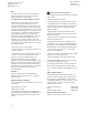
Before You Start Before installing your system, read and understand the safety instructions. Be sure you have all the necessary parts, tools, and test equipment, listed below. 1 Read Important Safety Information on Page 2 2 Check Shipping Container Contents ■ AmpliCenter Unit ■ Power Cord ■ This Installation and Use guide AMPLICENTER D20, D100, D300 INSTALLATION MANUAL AT&T PagePac Plus AmpliCenter Installation and Use POWER CORD Figure 1.
Installation Steps 1 NOTE: If installed next to other equipment, including the PagePac Plus Controller and Zone Expansion Units, leave at least four inches space above and below for proper ventilation. Mount the PagePac Plus AmpliCenter to either the wall, cabinet or a 19" rack. SIDE VIEW AMPLICENTER Figure 2. Wall Mounted Hardware FRONT DETAIL TYPICAL COMBINATION PAN HEAD PILOT POINT #10 - 32 (TYPICAL) REAR DETAIL POWER STRIP Figure 3.
2 Connect music input wires to Left, Right, and Ground terminals, if stereo, or Left and Ground, if not. 70V OUT NOTE: The optional audio background music source can be a CD or tape player, AM, FM, or commerical radio, or other audio device. PAGE IN MUSIC IN AMPLICENTER BACK PANEL LOW FREQ CUT-OFF MONO STEREO Figure 4. Music Input Connections on AmpliCenter 3 Hookup speaker cable to AmpliCenter. NOTE: If more than one speaker cable is routed to the AmpliCenter a connector block is necessary.
5 NOTE: Refer to the Connectivity Chart on page 12 and 13 to determine the page line output type of your telephone system. In most cases, the setting will be Loop Start. You can also check with your telecommunications manager. Set the AmpliCenter Telephone Mode Selection Switch to match the page output type of your telephone system.
The Page VOX (voice activation) sensitivity is turned fully counter-clockwise if the Dry Loop feature is not used. Adjust Music Input level. Clockwise rotation will increase the level. Listen and set to a comfortable level. 4. Using a telephone from the host system, dial the paging extension. Speak into the telephone in a normal manner. Your voice should be heard from all connected speakers.
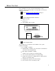
Troubleshooting Some common problems encountered when the paging system is not operating are described below. Check each item in the order listed. 1. No AC power to AmpliCenter. 2. Host telephone system failure. 3. Host system page port failure. 4. A hardwire disconnect between host system and PagePac Plus. 5. AmpliCenter switch settings tampered with. 6. Volume low due to DTMF volume level not being set properly.
Controls and Indicators, Terminals and Connectors Figure 10 shows the controls and indicators, terminals and connectors on the rear panel of the AmpliCenter. Table 2 identifies them by function. AMPLICENTER Figure 10. AmpliCenter Controls and Indicators, Terminals and Connectors Table 2. Controls and Indicators, Terminals and Connectors 1. AC Power in: 105 – 125 VAC, 210-250 VAC, 50/60 Hz, (voltage auto-selectable within unit) 2. 0dBm out, an auxiliary output that differs from the main 70.
Connecting Speakers 1 2 3 Locate and mount all speakers in accordance with the floor plan drawing for this installation Connect each speaker to the appropriate Home Run or Speaker-to-speaker wiring scheme as shown on the wiring plan (See Figure 11, below) Test speaker wiring for short circuits Measure the resistance of each home run wire run with an ohmmeter. Any pair indicating a value of less than 15 ohms must be rechecked for possible shorted wiring or speakers. Correct and problems and retest.
Example System Setups Figure 12 illustrates the interconnection between the AmpliCenter and the Controller, if used. Figure 13 illustrates the interconnection of two or more AmpliCenters. AMPLICENTER NOTE: If the AmpliCenter is used with the PagePac Plus Controller, refer to the Controller Installation and Use Guide for detailed instructions.
Connectivity Chart The Connectivity chart gives the interface requirements for the host telephone systems listed. This information is then used to set the telephone mode function switch on the PagePac Plus AmpliCenter. Table 3. PagePac Plus Connectivity Chart Merlin Plus Merlin 206/820 C.O. Line Page Port C.O.
Table 3. PagePac Plus Connectivity Chart (Continued) Comkey 416, 718, 1434 and 2152 Set Mode Station to: Dimension Horizon C.O. Line Intercom C.O. Line Analog Station Intercom C.O. Line Analog Station Aux. Port Yes – Yes – – Yes – – Ground S t a r t3 – – Yes – – Yes – – Dry Loop (HI Z) – – – – – – – – Dry Loop (600 Ω ) – – – – – – – Yes Note 2 Loop Start NOTES: 1. 2. 3. 4.
Specifications Table 4 describes the specifications of the AmpliCenter D20, D100, and D300 models. Table 4. AmpliCenter Specifications Features ■ ■ ■ ■ Telephone Paging Access: The AmpliCenter accepts inputs from telephone system (PBX) ground start or loop start trunk ports, dry loop 600 ohm page ports, dry loop (hi Z), or amplified microphones. Music interface: The AmpliCenter is the unit to which the background music source (CD, radio, tape player) is connected, for distribution to the paging system.
1994 AT&T All Rights Reserved Printed in U.S.A. AT&T 463-248-202 0II722051-300 Issue 3, Sept.