
Installation guide

Synapse Installation Guide Back to Contents
Getting Started 56
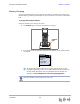
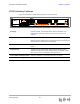
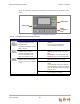
Figure 29 and Table 5 provide an illustration and description of the PSTN Gateway front
panel.
Figure 29. PSTN Gateway Front Panel
Power LED
Status LEDs
Menu
Navigation
Keys
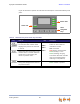
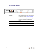
Table 5. PSTN Gateway Front Panel Keys and LEDs
Key Used To: LED Description
Navigate through the menus, and to
increase/decrease editable fields.
Highlight the previous or next item
in the list.
LINE 1
LINE 2
LINE 3
LINE 4
Line-status LEDs indicate the
status for each PSTN line.
Indications include:
Off—Connected.
Red (steady)—Disconnected.
Green (steady)—In use.
Green (flashing)—Ringing.
Line-status LEDs flash red after
lines are connected (while
matching line impedance).
Display the Main menu when in idle
mode or while in network detection
mode; save current setting and
return to previous menu.
Terminate current operation without
saving new settings and to return to
the previous menu.
POWER Off—No power to the device.
Green—Power is present.