Synapse® Installation Guide © 2010–2011 Advanced American Telephones. All Rights Reserved. AT&T and the AT&T logo are trademarks of AT&T Intellectual Property licensed to Advanced American Telephones, San Antonio, TX 78219. Synapse® is a registered trademark of Advanced American Telephones. Issue 1 .
Synapse Installation Guide CONTENTS Preface........................................................................................................................................................................ 6 Using This Guide ...........................................................................................................................................................................................................................................6 Topic Navigation ..........................
Synapse Installation Guide Gateway and ATA Placement..............................................................................................................................................................................................................37 Rack Mounting ...........................................................................................................................................................................................................................37 Wall Mounting .
Synapse Installation Guide Deskset IP Settings...................................................................................................................................................................................................................................82 Set/Edit Static IP ......................................................................................................................................................................................................................
Synapse Installation Guide Troubleshooting....................................................................................................................................................142 Common Troubleshooting Procedures ........................................................................................................................................................................................ 143 Resetting Devices .............................................................................
Synapse Installation Guide SB67060 T1 Gateway Parts List .................................................................................................................................................................................... 210 SB67020 Deskset Parts List............................................................................................................................................................................................. 211 SB67030/031 Deskset Parts List ...................
Synapse Installation Guide PREFACE This Installation Guide provides instructions for installing and setting up your Synapse system with software version 1.9.5 or later. See page 13 for instructions on checking the software version on the Gateway, the Deskset, and the ATA. Before using this AT&T product, please read “Appendix E: Important Safety Instructions” on page 217. Please read this guide thoroughly for all the information necessary to install your new AT&T product.
Synapse Installation Guide Topic Navigation This guide allows easy navigation between topics and the ability to return to your original topic. Figure 1 illustrates the navigation conventions within the guide. Synapse Installation Guide PREFACE Back to with Table of version Contents This Installation Guide provides instructions for installing and setting up your Synapse system software 1.9.2 or later.
Synapse Installation Guide Text Conventions Table 1 lists text formats and their uses. Table 1. Description of Text Conventions Text Format Description Screen Identifies text that appears on the screen in a title, menu, or prompt. HARD KEY or DIAL-PAD KEY Identifies a hard key, including the dial-pad keys. Identifies a soft key. Figure 1, Table 1 Identifies a figure or table.
Synapse Installation Guide Deskset and Cordless Handset Menu Navigation To access items in the menus, you can either use the Navigation key to highlight the function and press SELECT or press a numeric key on the dial pad. The procedures in this guide use the numeric keypad entry as the preferred method for selecting a function.
Synapse Installation Guide C HAPTER 1 INSTALLATION This section describes the physical installation of the Synapse devices. Each system must include at least one PSTN Gateway or one T1 Gateway. Each PSTN Gateway supports up to four analog telephone lines. Up to four PSTN Gateways can support up to 16 analog telephone lines. The T1 Gateway supports up to 23 T1 PRI voice channels.
Synapse Installation Guide System Overview 1. 1 AT&T SB67010 PSTN Gateway — Each PSTN Gateway provides access to up to four analog outside telephone lines. The system can have up to four PSTN Gateways, supporting up to 16 telephone lines. Information that is only about the PSTN Gateway is designated by [PSTN] in this guide. 2. AT&T SB67060 T1 Gateway — The T1 Gateway supports the T1 PRI (Primary Rate Interface) that provides access to up to 23 voice channels to support up to 23 simultaneous calls.
Synapse Installation Guide 7. AT&T SB67050 Analog Terminal Adapter (ATA - Optional) — The ATA allows the integration of non-Synapse devices, such as analog telephones, a fax machine, overhead paging equipment, and a music-on-hold source into the Synapse system. It also provides Group Mailboxes to allow different people to access the same Mailbox. The system can have only one ATA. Information that is only about the ATA is designated by [ATA] in this guide. 8.
Synapse Installation Guide Software Version Compatibility Systems with software versions 1.9.5 and later support the features described in this guide. All Gateways, ATAs and Desksets must have compatible software versions installed. To determine the software version of Gateways and the ATA from the device front panel, from idle, press SELECT, SELECT, and then DOWN. The software version appears, as shown in Figure 3.
Synapse Installation Guide System Installation Overview Figure 6 illustrates how the Synapse system differs from conventional telephone systems in that calls are not coordinated by a central controller. Instead, the system uses a distributed control system over a new or existing LAN. Figure 6.
Synapse Installation Guide If you install one SB67010 PSTN Gateway or SB67060 T1 Gateway and then one Deskset, the feedback described in this guide matches what you see on your system devices. A system must have at least one PSTN Gateway or one T1 Gateway. There can be up to four PSTN Gateways, and a system can include both a T1 Gateway and PSTN Gateways. Figure 7 illustrates the minimum components needed to make the system work (blue line = telephone; red lines = Ethernet).
Synapse Installation Guide System Installation Overview with Optional Analog Terminal Adapter If you have analog devices that you want to attach to the system, you will need an AT&T SB67050 Analog Terminal Adapter (ATA). The Synapse system supports one ATA per system. The ATA allows you to attach hardware such as conference phones, overhead paging equipment, a fax machine, or a source for Music On Hold (MoH) to Synapse.
Synapse Installation Guide Recommended Installation Sequence 1. Prepare your site for installation. See “Site Preparation” on page 32. 2. Install the PSTN and/or T1 Gateways. See “Gateway Installation” on page 41. 3. If you have only one Gateway, install the first Deskset. See “Deskset Installation” on page 45. This Deskset is assigned extension number 200 with no Direct Inward Dialing. 4. If necessary, change the mode of operation from Call Appearance mode to Line Appearance mode.
Synapse Installation Guide 8. 9. Connect any analog device such as a fax machine, paging system, or door phone to the ATA. For more information, see: “Connecting Analog Telephones” on page 53 “Connecting a Fax Machine” on page 54 “Connecting an Overhead Paging System (OHP)” on page 55 “Station Port (FXS) Door Phone Support” on page 27. Configure the system using the WebUI. See “System Configuration” on page 88. 10. Complete post-installation tasks.
Synapse Installation Guide Planning Your System and Network Configuration This section describes several important configuration options that you should be aware of before you install the Synapse system. These options include Operation Mode (Call Appearance versus Line Appearance), IP addresses and connectivity, extension number assignments, analog bypass lines and analog telephones in the Synapse system.
Synapse Installation Guide Systems using Line Appearance mode must use PSTN Gateways only. An optional ATA is also compatible with Line Appearance mode. For more information, see “ATA Fax Line Configuration” on page 36. A system using Line Appearance mode cannot support the T1 Gateway, Ring Groups, Call Queue and some Deskset-specific features. For more information, see the Synapse Administrator’s Guide at www.telephones.att.com/synapseguides.
Synapse Installation Guide 2. The Synapse Administrator can manually assign a static system IP address. This IP address does not change, even when there are network or AC power interruptions. Some installations will require manual static IP assignment. A switched-network topology is recommended. This topology refers to the network virtual shape or structure and does not necessarily reflect the physical layout.
Synapse Installation Guide Overhead Paging Overview You can set up either single or multi-zone external overhead paging (OHP), as shown in Table 2, but only one OHP system can be connected to the ATA. You can also use a loud ringer device, either on its own or with your existing OHP paging system, if supported. For more information, see “Loud Ringers” on page 31.
Synapse Installation Guide If your OHP is single-zone, you will have to decide whether it requires an FXS connection or an AUX OUT connection. You can only connect a multi-zone OHP to an ATA FXS port, i.e. a multi-zone OHP system cannot be connected to the AUX OUT port. Equipment that can interface with the AUX OUT jack can be “dumb” in its audio output. It doesn't require any exchange of signals to be ready to broadcast.
Synapse Installation Guide Single-Zone OHP equipment connected to one of the FXS ports: Use this configuration to connect paging equipment that interfaces through a telephone line. Typically, any OHP that connects to an FXS port has some intelligence to go off and on hook or otherwise send a signal back to the pager. These are generally controllers or telephone interfaces with controls and settings.
Synapse Installation Guide Multi-Zone Paging Broadcasts to speakers grouped into separate zones. Since the multi-zone OHP systems require zone selection, they cannot be combined into one zone together with Synapse Desksets. Multi-Zone OHP equipment connected to one of the FXS ports: When paging is configured as a multi-zone OHP, a dedicated Overhead Paging zone automatically appears as the last entry in the Deskset paging menu.
Synapse Installation Guide Verified Overhead Paging Devices Table 3 lists OHP systems that have been demonstrated to work with the Synapse System as of the publication of this document. More OHP systems may also have qualified for this list. For more information, call 1 (888) 916-2007. In Canada, dial 1 (888) 883-2474. Table 3.
Synapse Installation Guide Door Phones Overview Door phones and their associated door-entry mechanisms have become a common accessory in business phone systems. Door phone systems provide an easy method for Deskset users to attend to someone who is present at a door elsewhere. Synapse supports two types of door phones: Station Port (FXS) and Trunk Port (FXO). The system lets you select which Desksets will be notified by the door phone.
Synapse Installation Guide Trunk Port (FXO) Door Phone Support A Trunk Port (FXO) door phone can be connected to any one of the four Line (FXO) ports on a Synapse SB67010 PSTN Gateway as shown in Figure 13. The FXO door phone can be configured to call either a single extension or a group of extensions (a Ring Group). You can use the WebUI to configure an FXO door phone. For more information, see “Configuring a Trunk Port (FXO) Door Phone” on page 129.
Synapse Installation Guide Tested Door Phone Models Table 4 lists door phones that have been demonstrated to work with the Synapse System as of the publication of this document. More door phones may also have qualified for this list. For more information, call 1 (888) 916-2007. In Canada, dial 1 (888) 883-2474. Table 4.
Synapse Installation Guide Connecting Analog Devices to the ATA The ATA allows you to attach the following analog devices to the ports and jacks identified in Figure 37 on page 52. Most options require the system administrator to configure the feature in the WebUI. See “The Web User Interface (WebUI)” on page 89 for information on configuring and using third-party devices. If you are planning to install more than one type of analog equipment, make sure there are suitable ATA ports available and configured.
Synapse Installation Guide Loud Ringers Loud Ringer devices must be connected to an FXS port assigned as Voice (default setting). Loud Ringers can be used for alerting users of an incoming call via a loud speaker and are treated within Synapse as a regular analog phone instead of OHP equipment. This type of overhead alerting can only be done by including the voice FXS port in a Ring Group.
Synapse Installation Guide Site Preparation This section describes how to prepare your site for a successful Synapse system installation. Network Requirements For more information on the network configuration, see “Planning Your System and Network Configuration” on page 19. A switched network topology is recommended for your LAN (using standard 10/100 Ethernet switches that carry traffic at a nominal rate of 100 Mbit/s). The office LAN infrastructure should use Cat.-5 (or better) cable.
Synapse Installation Guide Placement Considerations Avoid placing any Synapse component too close to the following: Communication devices, such as television sets, DVD players, or other cordless telephones Excessive heat sources Noise sources, such as a window with traffic outside, motors, microwave ovens, refrigerators, or fluorescent lighting Excessive dust sources, such as a workshop or garage Excessive moisture Extremely low temperature Mechanical vibration or shock, such as
Synapse Installation Guide Other Preparations Before installing the Gateway and Desksets, the following preparations may need to be taken: All PSTN lines must be gathered into one access point situated no more than 9 feet (2.74 m) from the Gateway location. If rewiring is required, contact your telephone service provider and request the help of a qualified technician.
Synapse Installation Guide Assigning Telephone Lines and Extensions This section discusses various telephone line configuration issues to consider. Providing Limited Telephone Service During AC Power Outages PSTN Gateway The fourth line on each PSTN Gateway is a Bypass port that works during AC power failures. If you have a PSTN line plugged into LINE 4, connect a line-powered analog telephone to the RJ-11 jack labeled BYPASS for telephone service during power failures.
Synapse Installation Guide ATA Fax Line Configuration To support fax on the Synapse system, you should consider where the fax is, and which telephone line will be used for incoming faxes. Fax line configuration for the Synapse system differs depending on whether you are using a PSTN Gateway or a T1 Gateway. PSTN Gateway The PSTN fax line can be connected to any FXO port (LINE 1–4) on the PSTN Gateway. However, trunks for outgoing calls are seized in ascending order (LINE 1 then LINE 2, and so on).
Synapse Installation Guide Gateway and ATA Placement You can place the Gateway or ATA on a tabletop, mount it into a standard 19-inch metal rack, or wall mount it. The PSTN Gateway must be installed within three feet of the building ground point. Install each device using the following instructions. Rack Mounting To mount the Gateway or ATA into a standard 19-inch rack: Locating Indent 1. Remove the two mounting brackets and six screws from the packing tissue. 2.
Synapse Installation Guide Wall Mounting To mount the Gateway or ATA to a wall: You can mount the Gateway or ATA to a wall using the two mounting slots on the bottom of the device. Ensure that the device is oriented as shown in Figure 17 to allow air to flow vertically through the ventilation holes on each side of the device. 1. Install two pan-head screws (with ¼-inch diameter head) 7 ⅞ inches (20 cm) apart. The screw shaft diameter should be ⅛-inch (3.2 mm).
Synapse Installation Guide Grounding The SB67010 PSTN Gateway, the SB67060 T1 Gateway, and the SB67050 Analog Terminal Adapter must be connected to reliable earth ground. The connection to earth ground must be verified by qualified personnel. The SB67010 PSTN Gateway must be connected to reliable earth ground using the supplied ground wire connected to a terminal on the back of the Gateway chassis.
Synapse Installation Guide To ground the Gateway or ATA: 1. Acquire a grounding cable of 18 AWG or greater gauge. For the PSTN Gateway, use the supplied grounding cable. 2. Locate the device near the building ground point, usually located at the electrical breaker box. The PSTN Gateway must be within three feet (91.4 centimeters) of the building ground point. If you are unsure about the location of the building ground point or how to ground the device, contact the facilities manager. 3.
Synapse Installation Guide Gateway Installation To install the Gateway: 1. Install a Gateway first. Plug the AC plug into an electrical outlet not controlled by a wall switch and the DC plug into the DC jack, as shown in Figure 20. Wait up to one minute until the screen lights up. 2. Plug a grey Cat.-5 LAN cable for the PSTN Gateway or yellow Cat.-6 LAN cable for the T1 Gateway into the Ethernet port marked LAN. Use the supplied cables or a comparable substitute.
Synapse Installation Guide To install the Gateway: (Continued) The Gateway takes about a minute to power up. After another Synapse device is installed, and after the Gateway has found the network and the other Synapse device, Synchronized appears on the third line of the display, as shown in Figure 21. This is the Idle screen. PSTN Gateway The time and date may not be correct. You can set the time and date on the System Basic Settings page in the WebUI or using the Deskset Admin Settings menu.
Synapse Installation Guide To connect the PSTN Gateway telephone lines: 1. Remove the plastic covers from the Gateway PSTN (telephone) jacks to be used, marked LINE 1 through LINE 4 and BYPASS, as shown in Figure 22. Telephone Line LEDs LINE 1 through LINE 4 LINE 1 LINE 1 LINE 2 LINE 3 BYPASS LINE 4 BYPASS LINE 2 LINE 3 LINE 4 POWER UP DC 5.1V LAN RESET DOWN SELECT - + CANCEL Figure 22.
Synapse Installation Guide [ To connect the T1 Gateway T1 cable: Plug the black T1 cable into the Gateway T1 Port, as shown in Figure 24, and into your T1/PRI network device from your service provider. Do not make any calls until the POWER and the SYN/ACT LEDs are green. See “T1 Gateway Features” on page 67. The SB67060 T1 Gateway must use only No.26 AWG or larger Telecommunications line cord to reduce the risk of fire. For customer service or product information, visit our website at 1 (888) 916-2007.
Synapse Installation Guide Deskset Installation Figure 25 identifies the features on the bottom and side of the Deskset. You can install the Deskset on a desktop or mount it on a wall. Figure 25 represents the SB67030/031 Deskset. Although the SB67020 is slightly different, its features have the same basic layout. The SB67031 Deskset is compatible only with Synapse systems with software version 1.9.5 and later. Ensure you have upgraded your system to software version 1.9.
Synapse Installation Guide To attach the Desktop Stand for desktop installation: Option 1 Option 2 Figure 26. Deskset Stand Options Flexible tabs 1. Select a Deskset position. The desktop setup requires the Deskset Stand and provides two positions, Option 1 at 45° and Option 2 at 60°, as shown in Figure 26. If you use Option 2, rotate the Handset tab as explained in “To rotate the Handset tab for wall and Deskset Option 2 installation:” on page 47 2.
Synapse Installation Guide To rotate the Handset tab for wall and Deskset Option 2 installation: 1. Press the switch hook and slide the Handset Tab toward the top of the base, as shown in Figure 29. 2. Rotate the Handset Tab 180°, as shown in Figure 30, so that the “hook” is at the top. 3. Slide the Handset Tab back into the base, as shown in Figure 31. Switch hook Handset Tab Figure 29. Handset Tab “Hook” Figure 30. Handset Tab Rotation Figure 31.
Synapse Installation Guide To connect the Cat.-5 LAN cable to the Deskset: With a PC: If there is a networked computer and no extra Ethernet wall jacks near the Deskset, then plug the PC Ethernet cable into the Deskset so the Deskset and PC share the same network connection. 1. Unplug the Cat.-5 Ethernet cable from your computer. 2. Plug that Cat.-5 Ethernet cable into the Network port on the back of the Deskset, as indicated in Figure 32. 3. Plug another Cat.
Synapse Installation Guide To connect the Cat.-5 Ethernet cable to the Deskset: (Continued) Without a PC: If the Deskset has a dedicated network connection, then connect the Deskset to the network connection only. 1. Plug a Cat.-5 Ethernet cable into the Network port on the back of the Deskset, as indicated in Figure 32 on page 48. 2. Plug the other end into the Ethernet wall jack. To connect power: [020/031] If you are using PoE, connecting the Deskset to the network also connects the power.
Synapse Installation Guide To install the Deskset on a wall: WallMount Screws 1. Plug the Ethernet cable into the port on the back of the deskset. (See “To connect the Cat.-5 LAN cable to the Deskset:” on page 48.) 2. Plug the power adapter into the jack on the back of the deskset. Skip this step if using POE. (See “To connect power:” on page 49.) 3. Place the Deskset base over the mounting plate above the mounting studs as shown in . 4. Slide the Deskset base down as shown in 5.
Synapse Installation Guide To connect the corded handset and an optional corded headset: Connect the corded handset: 1. Plug the coiled end of the handset cord into the handset jack on the left side of the telephone, as identified in Figure 35. 2. Plug the end of the handset cord with the longer straight portion into the handset, then hang up.
Synapse Installation Guide SB67050 ATA Installation To install the ATA: 1. After installing at least one Deskset, plug the AC plug into an electrical outlet not controlled by a wall switch and the DC plug into the DC jack, as shown in Figure 37. Wait up to one minute until the screen lights up. To prevent the loss of ATA-supported services during power outages, plug the AC power plug into an Uninterruptible Power Supply (UPS). 2. Plug a Cat.-5 Ethernet cable into the port marked LAN.
Synapse Installation Guide Connecting Analog Telephones To install analog telephones: 1. Remove the plastic covers from the FXS 1 and FXS 2 (telephone) ports to be used on the ATA. 2. Plug up to two telephone lines from analog telephones into the ATA FXS 1 and FXS 2 ports, as shown in Figure 39. ATA Analog Telephone/ Conference Phone Analog Telephone/ Conference Phone Figure 39.
Synapse Installation Guide Connecting a Fax Machine To install a fax machine: 1. Remove the plastic covers from the FXS 1 or FXS 2 (telephone) port to be used on the ATA. 2. Plug a telephone line from the fax machine into the ATA FXS 1 or FXS 2 port, as shown in Figure 40. 3. Configure the fax connection in the WebUI. See ““Fax Settings” on page 121” for information on configuring the ATA to work with your fax machine. ATA Fax Machine Figure 40.
Synapse Installation Guide Connecting an Overhead Paging System (OHP) A Single Zone or Multi-Zone system can be integrated into an existing Synapse network. The control unit or analog amplifier for the Overhead Paging system connects directly to the ATA via an FXS or the AUX OUT jack, depending on the type of paging system. Synapse supports most OHP systems that support PBX station ports or auxiliary audio-out connections to a PBX. Some settings for the OHP may have to be changed to work with Synapse.
Synapse Installation Guide To install an overhead paging system: 1. Remove the plastic cover from the FXS 1 or FXS 2 port to be used on the ATA. 2. Plug the telephone line from the OHP device into the FXS 1 or FXS 2 port, or plug an audio cable from the OHP device into the ATA AUX OUT jack, as shown in Figure 41 on page 55, depending on the requirements of the paging system.
Synapse Installation Guide Connecting a Music on Hold Source To install a music on hold source: 1. Use the supplied Auxiliary Audio Cable to plug a streaming audio source, such as a radio or MP3 music player, into the ATA AUX IN jack as shown in Figure 43. If the supplied cable does not connect to your music source, use another cable that will connect your device to the 3.5 mm AUX IN jack. This audio source must have a volume control.
Synapse Installation Guide SB67040 Cordless Handset Installation The SB67040 Cordless Handset requires registration to an SB67030/031 Deskset. The SB67020 Deskset does not support the SB67040 Cordless Handset. The SB67040 Cordless Handset is not supported when the system is in Line Appearance mode. Charger Installation Place the Handset in the charger when not in use. To plug the Handset charger into AC power: 1. Plug the power adapter into an electrical outlet not controlled by a wall switch. 2.
Synapse Installation Guide Battery Installation The Handset uses a rechargeable 2.4v nickel-metal hydride cell (NiMH) battery pack. To install the Handset battery: Color-Coded Battery Connector 1. Remove the battery cover by pressing and sliding the cover downward, as shown in Figure 45. 2. Plug the battery connector securely into the plug inside the Handset battery compartment, matching the color-coded label. Use only the supplied rechargeable battery or replace it with battery model BT8001.
Synapse Installation Guide Battery Charging Charge the Handset battery for at least 16 hours before use. When fully charged, the Handset battery provides approximately five hours of talk time or three days of standby time. To charge the Handset battery: Place the Handset in the charger, as shown in Figure 47. CHARGE light Figure 47. Handset in Charger The CHARGE light is on when the Handset is charging.
Synapse Installation Guide TL7600 Cordless Headset Installation The TL7600 Cordless Headset requires registration to an SB67030/031 Deskset. The SB67020 Deskset does not support the TL7600 Cordless Headset. Charger Installation To install the TL7600 charger: 1. Plug the small end of the charger power adapter into the jack on the underside of the charger, then route the cord through the slot as shown in Figure 49. 2.
Synapse Installation Guide Battery Installation Install the battery as shown below. For optimal performance, charge the Headset battery for at least six hours before use. When not in use, recharge the Headset by returning it to the Headset charger. To install a battery: Figure 50. Remove Battery Door Insert Battery Insert Plug 1. If the battery door is attached, press on both sides of the battery compartment cover and lift the cover up and off as shown in Figure 50. 2.
Synapse Installation Guide Battery Charging After installing the battery, charge the Headset by placing it in the Headset charger as shown below. Before registration, the Headset ON/OFF light flashes twice every five seconds whether the Headset is charging or not. After registration, the Headset ON/OFF light is on when the Headset is charging. To charge the battery: 1. Insert the Headset into the charger as shown in Figure 53. 2.
Synapse Installation Guide C HAPTER 2 GETTING STARTED This chapter gets you started with configuring the Synapse system from the devices. Most of these functions are duplicated in the easier-to-use WebUI described in the next chapter, but if you need to assign static IP addresses, they must be set at each device. You can only directly reset a device from the device, although some functions in the WebUI include device resets.
Synapse Installation Guide PSTN Gateway Features Figure 55 illustrates the PSTN Gateway features and connections. LINE 1 LINE 1 1 LINE 3 LINE 3 LINE 4 BYPASS DC 5.1V LAN RESET LINE 4 POWER UP LINE 2 LINE 2 DOWN SELECT CANCEL - 2 3 4 5 + 6 Figure 55. PSTN Gateway Features and Connections 1. Display Provides system and network status, device information, and configuration data. See “Gateway Front Panel Interface” on page 69. 2. Reset When pressed momentarily, restarts the Gateway.
Synapse Installation Guide Figure 56 provides an illustration and description of the PSTN Gateway front panel. Line-Status LEDs Power LED Menu Navigation Keys Key - Used To: LED Navigate through the menus, and to increase/decrease editable fields. Description Line-status LEDs indicate the status for each PSTN line. Indications include: Off – Connected. Red (steady) – Disconnected. Green (steady) – In use. Green (flashing) – Ringing.
Synapse Installation Guide T1 Gateway Features Figure 57 illustrates the T1 Gateway features and connections. 1 2 3 4 5 Figure 57. T1 Gateway Features and Connections 1. Display Provides system and network status, device information, and configuration data. See “Gateway Front Panel Interface” on page 69. 2. Reset When pressed momentarily, restarts the Gateway. When pressed and held for more than five seconds and with the LAN cable not connected, restores factory defaults. 3. T1 Port 4.
Synapse Installation Guide Figure 58 provides an illustration and description of the T1 Gateway front panel. . Status LEDs Power LED Menu Navigation Keys Key Used To: LED Description Navigate through the menus, and to increase/ decrease editable fields. Highlight the previous or next item in the list, respectively. Off – T1 is not synchronized with T1 network. Green – T1 Synchronization. Green (flashing) – Active call.
Synapse Installation Guide Gateway Front Panel Interface You can access basic information and perform some configuration tasks using the Gateway’s front panel. Most of these tasks are easier to do using the WebUI. See “The Web User Interface (WebUI)” on page 89. The Gateway displays the Idle screen upon completion of the power-up sequence. Use the Gateway Main menu to perform some system operations.
Synapse Installation Guide Press the key to highlight an entry, as shown in Figure 60, then press to see information about your Gateway or your Network. Select Configuration to view or modify some Gateway settings. Here is the information you can see in Device Information and Network Status: Device Information Figure 60.
Synapse Installation Guide Gateway Configuration Press / in the Gateway Main menu until Configuration is highlighted, as shown in Figure 61, and press to display the Configuration menu. The current setting is indicated with . You can use this interface or the WebUI to upgrade software. Configuration — Current Gateway settings. Figure 61. Gateway Configuration Getting Started Auto IP — Is set automatically. Static IP — You can change the static IP only from the Gateway.
Synapse Installation Guide Upgrade Gateway Software If you have system settings that you want to retain, back up the settings before upgrading the system software. To upgrade the Gateway software to the latest version: / in the Gateway Main menu until Configuration is highlighted and to display the Configuration menu, as shown in Figure 62. 1. Press press 2. Press to highlight Upgrade Software and press to initiate the software upgrade process.
Synapse Installation Guide To upgrade the Gateway software to the latest version: (Continued) 3. 4. If new software is available, you are prompted to initiate the upgrade by pressing or abort by pressing . Once the downloading starts, the display indicates the progress as shown by the percentage indicator, as shown in Figure 63. If the upgrade process is interrupted by removing the server connection, no restart occurs.
Synapse Installation Guide ATA Features When the ATA is first connected to your LAN, the two FXS ports are configured as POTS phone lines and assigned the next available extension numbers. ATA extension numbers do not appear in the Extension list on Deskset screens. They do, however, appear on Call Logs, Redial lists, and Message lists. The two ATA extensions do not count toward the 100-extension limit of the Synapse system. Configure the interface to these analog devices through the WebUI.
Synapse Installation Guide Figure 65 provides an illustration and description of the ATA front panel. Status LEDs Power LED Menu Navigation Keys Key Used To: LED Description Navigate through the menus, and to increase/decrease editable fields. Station jack status LEDs indicate: Highlight the previous or next item in the list, respectively. Green (steady) – Line activity detected Display the Main menu when in idle mode or while in network detection mode.
Synapse Installation Guide ATA Front Panel Interface You can access basic information and perform some configuration tasks using the ATA front panel. These tasks are easier to do using the WebUI. See “The Web User Interface (WebUI)” on page 89. The ATA displays the Idle menu after powering up. Access the ATA Main menu to perform the system operation functions. The Idle screen is different, but the menus are the same as that of the PSTN Gateway.
Synapse Installation Guide ATA Configuration Press / in the ATA Main menu until Configuration is highlighted, as shown in Figure 68, and press to display the Configuration menu. The current setting is indicated with . You can use this interface or the WebUI to upgrade software. Configuration — Current ATA settings: Figure 68. ATA Configuration Getting Started Auto IP — Is set automatically. Static IP — You can change the Static IP only from the ATA.
Synapse Installation Guide Upgrade ATA Software If you have system settings that you want to retain, back up the settings before upgrading the system software. To upgrade the ATA software to the latest version: / in the ATA Main menu until Configuration is highlighted and press to display the Configuration menu, as shown in Figure 69. 1. Press 2. Press to highlight Upgrade Software and press to initiate the software upgrade process.
Synapse Installation Guide To upgrade the ATA software to the latest version: (Continued) 3. Figure 70. Downloading Software Getting Started 4. If new software is available, you are prompted to initiate the upgrade by pressing or abort by pressing . , Once the downloading starts, the display indicates the progress as shown by the percentage indicator, as shown in Figure 70. The device restarts automatically once the programming is completed.
Synapse Installation Guide Resetting Devices You may need to manually restart a device or return a device to factory defaults (see “Appendix B: Default Settings” on page 205). To reset a device, press the RESET button shown in Figure 71 and Figure 72 by inserting a pen or paper clip into the hole and applying pressure to the button. The T1 Gateway and ATA (not shown) have a RESET button in the same location on the front panel as the PSTN Gateway.
Synapse Installation Guide LINE 1 LINE 1 LINE 2 LINE 3 LINE 4 BYPASS LINE 2 LINE 3 LINE 4 POWER UP DOWN SELECT - CANCEL Reset Button Figure 71. PSTN Gateway Reset Button Reset Button Figure 72. Deskset Reset Button Getting Started DC 5.
Synapse Installation Guide Deskset IP Settings Synapse system devices are connected to a LAN so they can communicate with each other. See “System Installation Overview” on page 14 for a discussion of the Synapse network configuration and IP settings. To display the IP Settings screen: IP Settings 1. IP Configuration 1. Access the Admin Settings menu: Press MENU, then press 3 on the dial pad, then enter the Admin password (12345 is the default password), and press SELECT. 2.
Synapse Installation Guide To set the IP Configuration: IP Settings 1. IP Configuration 1. Access the Admin Settings menu: Press MENU, then press 3 on the dial pad, then enter the Admin password, and press SELECT. 2. Press 3 on the dial pad to display the IP Settings menu shown in Figure 75 and Figure 77. 3. On the 020 Deskset, press 1 to select IP Configuration. Static 2. Set/Edit Static IP 3. IP Status Use Use or or to mov e highlight. to cy cle through options. Quick Dial Save Figure 75.
Synapse Installation Guide Set/Edit Static IP If your business requires a static IP address, contact your network administrator. To set and edit static IP Address: IP Settings 1. IP Configuration 1. Access the Admin Settings menu: Press MENU, then press 3 on the dial pad, then enter the Admin password, and press SELECT. 2. Press 3 on the dial pad to display the IP Settings screen shown in Figure 80 and Figure 82. 3. Press 2 to display the screen shown in Figure 81 or Figure 83. 4.
Synapse Installation Guide IP Status This screen is for informational purposes only. To view the IP status: IP Settings 1. IP Configuration 1. Access the Admin Settings menu: Press MENU, then press 3 on the dial pad, then enter the Admin password, and press SELECT. 2. Press 3 on the dial pad to display the IP Settings screen shown in Figure 84 and Figure 86. 3. Press 3 to display the IP Status screen shown in Figure 85 and Figure 87. 4.
Synapse Installation Guide Upgrade Deskset Software To access the Deskset Software Upgrade feature: 1. Software Upgrade Scanning for Upgrades... &XUUHQW ,PDJH 9HUVLRQ V\QDSVH GV SHWUD Y LPJ 2. Access the Admin Settings menu: Press MENU, then press 3 on the dial pad, then enter the Admin password, and press SELECT. Press 5 to display the screen shown in Figure 90 or Figure 92. The system scans for an upgrade. 4XLFN 'LDO ([LW Figure 90.
Synapse Installation Guide To access the Deskset Software Upgrade feature: (Continued) 3. Software Upgrade No New Version Press to install the upgrade. The screen shown in Figure 96 or Figure 97 appears. If the device is sluggish or unresponsive during the upgrade process, see “A Synapse device becomes sluggish or unresponsive during or immediately after software upgrade.” on page 172. Current Image Version synapse-ds-petra-v1.7. .img Quick Dial Exit Figure 95.
Synapse Installation Guide C HAPTER 3 SYSTEM CONFIGURATION The WebUI consists of web pages with editable settings that allow you to administer the system. The WebUI is embedded in every SB67010 PSTN Gateway, SB67020 Deskset, SB67030/031 Deskset, and optional SB67050 Analog Terminal Adapter (ATA). When you access the WebUI, you are accessing it on the device, not on the Internet.
Synapse Installation Guide The Web User Interface (WebUI) The WebUI settings in this chapter are provided to enable you to commission a basic Synapse System with Gateways, Desksets, ATA, and an optional fax machine and paging system. These settings include: “System Settings” on page 94 “T1 Settings” on page 110 “ATA Settings” on page 115. In addition, please see “Updating Devices” on page 136 for important information about ensuring that Synapse devices have compatible software versions.
Synapse Installation Guide WebUI Overview . If two Synapse devices are connected to the LAN, and as long as one Synapse device is currently on the same subnet as a PC, you can use the WebUI to administer the system. Only one person should log in as system administrator at a time to prevent accidentally overwriting and losing intended changes. Any PCs used for configuring the WebUI must be connected to the same IP subnet as devices they will manage, or to other subnets that the PCs can communicate with.
Synapse Installation Guide Log in as Administrator To access the browser interface and log in: 1. Ensure your computer is connected to the same IP subnet as the Synapse system. You can connect your computer to the PC port on the back of a Deskset. 2. On the Deskset, press MENU then 4 to display the Deskset Information screen shown in Figure 101 or Figure 102. 3. Find the IP address on the Deskset Information screen. 4. Open a browser.
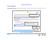
Synapse Installation Guide To access the browser interface and log in: (Continued) 6. Enter admin in the Login Name field and 12345 in the Password field, then click . You may change your Admin ID and password once you are logged in. Click topics from the navigation list on the left side of the WebUI to see them. You view and change settings in two different types of fields: dropdown lists and entry fields into which you type information.
Synapse Installation Guide Error Handling If you type an invalid value into one of the WebUI fields and click , the page is not saved. The WebUI displays an error message at the top of the page. The field with the incorrect value is highlighted in yellow, as shown in Figure 105. You can view a more detailed error description by resting your mouse pointer on the highlighted field. . Error Message Invalid Entry Figure 105.
Synapse Installation Guide System Settings When making changes to the System Settings through the WebUI, ensure that no one is using the system. You might need to make the changes after normal office hours. The WebUI settings available to you vary according to the system configuration. T1 and ATA settings and features are only available and visible in the WebUI when those devices are installed. Many settings available in Call Appearance mode are not available in Line Appearance mode.
Synapse Installation Guide Setting Line Appearance Mode By default, the Synapse system starts up in Call Appearance mode. If you need to change the appearance mode, change it at the beginning of the installation—after you have installed one Deskset but before you have installed all the Desksets. If possible, setting the appearance mode should be a one-time procedure. For a full list of system and Deskset settings that are affected by appearance mode changes, see the Synapse Administrator’s Guide at www.
Synapse Installation Guide Dial Plan Settings You can set up extension numbers for the Synapse system as either three- or four-digit extension numbers in the range of 100 to 999, or 1000 to 9999. You can also select the Prefix for the following: The Default Phone Extension Prefix determines the first digit to use for extension auto assignment. The Park Extension Prefix determines the first digit to use for parked calls (Call Appearance mode only).
Synapse Installation Guide To set the Dial Plan: (Continued) 3. Select the Default Phone Extension Prefix to be the initial digit used for automatically assigned extension numbers. For example, if set to 3, and you have existing extensions 2000 and 2001, the next automatically assigned extension numbers will increment beginning with 3000. The Default Phone Extension Prefix should not match the PSTN Trunk Prefix.
Synapse Installation Guide To set the Dial Plan: (Continued) 5. If the PSTN Trunk Prefix is set to none, ensure that the Park Extension Prefix does not conflict with the first digit needed to dial long-distance calls. For example, if the Park Extension Prefix is 1, then a PSTN call beginning “1-60” is not completed because the system instead looks for a parked call at extension 160.
Synapse Installation Guide To set the Dial Plan: (Continued) If the first few digits of an area code (e.g., 232-5550176) match an extension (e.g., Ext. 232), the extension is dialed. Ensure that commonly used area codes are not being used as extension numbers. If the Park Extension Prefix is the default 1, no long-distance calls can be completed, because the system tries to find a parked call for that number.
Synapse Installation Guide Direct Inward Dial (T1 Gateway) These settings apply to Call Appearance mode only. When the system is set to Call Appearance mode, use the Direct Inward Dial page to assign unique telephone numbers to specific Desksets. Callers can bypass the Call Queue, Auto Attendant, or Operator by using those telephone numbers. The T1 Gateway uses the Direct Inward Dial (DID) data from your Telephone Service Provider to automatically route incoming calls.
Synapse Installation Guide To set up Direct Inward Dial numbers: (Continued) For example, if a new Deskset was connected under the following conditions, the new Deskset would be assigned extension 204 and no DID number. Current Extensions: 201-203 taken, 204 and up available Current DIDs: 232-555-5201 available 232-555-5202 available 232-555-5203 taken Figure 112. DID Configuration, Part 1 You can also manually assign DID numbers. See “DID Assignments” on page 104.
Synapse Installation Guide To set up Direct Inward Dial numbers: (Continued) 3. As shown in Figure 113, select the Outgoing Caller ID for all Extensions. The outgoing caller ID is the Synapse user’s name and phone number that appears on the destination telephone if it is set up to receive and display the information. Select Per Extension (local setting) to have each extension send either the DID or System Pilot Number for the caller ID number. To set the phone number, see the Extension Settings menu.
Synapse Installation Guide To set up Direct Inward Dial numbers: (Continued) 5. Enter the DID range into the boxes beneath Add Direct Inward Dial Range. Click to enter the phone number range into the Current DID Ranges list. These ranges describe the DID numbers that your service provider assigned to you. The system cannot check whether you have subscribed to these DID numbers, but it checks that all numbers are ten digits long, with no spaces or hyphens, and that there are no more than 200 DID numbers.
Synapse Installation Guide DID Assignments These settings apply to Call Appearance mode only. If you did not enable automatic assignment (see “DID Configuration” on page 100), you must manually assign DID numbers. In addition to the manual assignment process described in this section, you can also manually assign DID numbers on the Extension Basic Settings page, and, if an optional ATA is present, on the ATA Settings page (see “ATA Settings” on page 115).
Synapse Installation Guide To manually assign Direct Inward Dial numbers: (Continued) 4. In the center of the page, use the Select DID drop-down list to select a DID Number. Only available DID Numbers appear in the list. Select Unassigned to release the DID Number and make it available. If you assign a DID Number to an extension that already has a DID Number assigned to it, the new number is assigned; the old DID Number is released. 5.
Synapse Installation Guide Trunk Naming You can name the system trunks for easier identification. For PSTN Gateways, you can assign names to all lines—up to 16, depending how many PSTN Gateways are installed. For the T1 Gateway, there is only one physical trunk, so only that one trunk can be named regardless of how many slots the T1 trunk supports. Renaming Gateway trunks is highly recommended in Line Appearance mode and when reserving trunks. See “Trunk Reservation (Outgoing Calls)” on page 107.
Synapse Installation Guide Trunk Reservation (Outgoing Calls) These settings apply to Call Appearance mode only. You can reserve a PSTN telephone line or a T1 channel for an extension, so that only that extension can use that telephone line (or channel) for outgoing calls. Trunk reservations apply only to outgoing calls. A user with a reserved trunk will not be able to make outgoing calls if all lines and channels are busy with incoming calls.
Synapse Installation Guide To reserve a trunk: 1. In the Navigation Menu at left, click System Settings, then Trunk Reservation. The current Trunk Reservation list appears, as shown in Figure 119. 2. Select an Extension from the first drop-down list. All extensions are listed, including FXS ports on the optional ATA that have been assigned to a telephone or Fax. Only one telephone line/channel can be reserved for each extension. 3. Select an available trunk from the Trunk Assigned drop-down list.
Synapse Installation Guide PSTN Gateway Trunk Routing (Incoming Calls) These settings apply to Call Appearance mode only. With a PSTN Gateway, all incoming calls to a specific telephone number can go directly to a specific destination. Calls to that phone number can be routed to an extension, Group Mailbox, or Ring Group. The Trunk Routing WebUI page only appears if there is a PSTN Gateway connected to the system. You can route calls on the T1 Gateway through Direct Inward Dialing.
Synapse Installation Guide T1 Settings These settings apply to Call Appearance mode only. You can modify the settings of your T1 connection. AT&T expects that most installations will use the default settings. Changing T1 settings resets the T1 Gateway and interrupts telephone service. To avoid disrupting service, AT&T recommends changing T1 settings outside of business hours. To configure the T1 settings: 1. In the Navigation Menu at left, click System Settings, then T1 Settings.
Synapse Installation Guide To configure the T1 settings: (Continued) 3. 4. Select the Clock Source for Gateway synchronization: Network. The telephone network maintains an extremely accurate timing source. Local. A clock source that is internally generated in the CSU (Channel Service Unit). Select the Line Buildout value from the dropdown list. The value and its units are determined by whether the CSU is on your premises or not. The default value is 0-133 feet/ 0 db.
Synapse Installation Guide To configure the T1 settings: (Continued) Figure 123. T1 Settings System Configuration 112 5. Select the Number of Channels. You can set the number of voice channels available on the T1 trunk according to the current service subscription. Channel 24 is reserved for PRI signaling. 6. Select the Lowest Voice Channel in cases where some channels are reserved for data transfer or if there are limited slots available. 7.
Synapse Installation Guide To configure the T1 settings: (Continued) 8. Click to save any changes or click to return to the previous page without saving the changes. When you click , the T1 Gateway resets itself. If there are Active Calls on the system, the system waits until the last call ends and the system is Idle. No new incoming or outgoing calls can be made until the reset is complete. During the reset, all LEDs on the T1 Gateway front panel turn off for approximately five to ten seconds.
Synapse Installation Guide T1 Diagnostics These settings apply to Call Appearance mode only. You can check the status of the T1 Gateway and select a loopback mode. Setting the loopback mode terminates any phone calls that are using the T1 Gateway. To view the T1 Status: 1. In the Navigation Menu at left, click System Settings, then T1 Diagnostics. The page shown in Figure 125 appears. The current T1 configuration is shown. 2.
Synapse Installation Guide ATA Settings Use the WebUI to configure the two FXS ports on the ATA. Once an ATA is connected to the Synapse network, the WebUI is updated to show all ATA-related menus and configuration items within menus. (The ATA must be running a compatible software version.) If the ATA is deleted (using the WebUI's Modify Device page), all these ATA-related menus and configuration items disappear. However, the device list continues to show a count of ATAs.
Synapse Installation Guide ATA FXS Ports Use the ATA Settings page to configure the two ATA FXS ports. To configure the two ATA FXS ports: 1. In the Navigation Menu at left, click ATA Settings. The page shown in Figure 126 appears. 2. Select an ATA device from the drop-down list. The rest of the ATA Settings page appears, as shown in Figure 127 on page 117. Figure 126.
Synapse Installation Guide To configure the two ATA FXS ports: (Continued) 3. For each FXS port shown in Figure 127: Enter the Display Name. The Display Name is used as part of the caller ID when an analog phone connected to the FXS port is used for internal calls. 4. Figure 127. ATA Settings (Call Appearance mode shown) System Configuration 117 Enter an Extension Number. Ensure that this is the same extension as selected in Fax Destination. See “Fax Configuration” on page 119.
Synapse Installation Guide Fax Overview This section describes how to configure the optional AT&T SB67050 ATA device for fax reception and transmission. Call Appearance mode only—If you have a dedicated fax line and low fax volume, the optional ATA offers fax switching so that you can use the fax line for both voice calls and faxes. If your fax does not have a DID number, when configured, the system detects incoming fax tones and routes those calls through the configured ATA FXS port to the fax machine.
Synapse Installation Guide Using the fax line for outgoing calls is not restricted, but the caller ID of the fax number, not the primary business telephone number, will be sent as caller ID. This may result in some confusion if the recipient returns a missed call via their caller ID Log as they will then experience the eight-second delay mentioned above. Callers who return calls to DID telephone numbers will be calling your fax machine.
Synapse Installation Guide The best mode for your installation depends on both your fax machine and your telephone line. In case of any fax issues, see “SB67050 Analog Terminal Adapter” on page 179 for more details. Use the WebUI to specify the Gateway and line being used as the fax line. Figure 128.
Synapse Installation Guide Fax Settings To configure the fax settings: 1. In the Navigation Menu at left, click Fax Configuration. The page shown in Figure 129 appears. The current ATA FXS Port settings are shown. 2. Enable or Disable the fax. When disabled, the incoming fax calls are directed like any other incoming calls, but faxes cannot be received. 3. [PSTN] Select the Fax Mode: G.711 or T.38. The Fax default setting is G.711. If the fax fails to work in G.711 mode, change it to T.38.
Synapse Installation Guide Setting Up Overhead Paging To set up external overhead paging: 1. In the Navigation Menu at left, click Overhead Paging. The page shown in Figure 130 appears. The current ATA FXS port settings are shown. 2. Enable or Disable the overhead Paging. 3. Select the Paging System Type. 4. Select the Paging Port. This is the FXS port or AUX OUT jack into which the OHP is connected 5. Select the Paging Delay.
Synapse Installation Guide Single-Zone Overhead Paging A single-zone overhead paging system issues a one-way broadcast to all overhead speakers. These speakers cannot be grouped into separate zones. A single OHP can be connected to either the AUX OUT jack or an FXS port. Single-zone OHP is automatically included when you page all extensions. To create a single overhead paging zone: Figure 131. Create Paging Zone System Configuration 123 1.
Synapse Installation Guide Single-Zone Overhead Paging Delay When attached to an FXS port, single-zone overhead paging may require the Page tone to be delayed. If this delay is too short, the beginning of the Page heard through the OHP speakers may be cut off. You or the system installer need to experiment to find the correct delay for the system. Set the delay in the WebUI. See “Overhead Paging Overview” on page 22. The delay starts after the user presses on the Deskset, as shown in Figure 132.
Synapse Installation Guide Multi-Zone Overhead Paging Unlike single-zone Paging, multi-zone Paging requires user input. In a multi-zone system, overhead speakers are grouped into zones. Each zone is assigned a number. The user pages the zone by starting a page and then entering the zone number (the exact method may vary depending on the third-party OHP system being used). Refer to your OHP system’s product documentation for installation and configuration instructions.
Synapse Installation Guide Paging Zones Use paging zones to set up extensions that can be paged as a group. For example, all extensions in the sales department could be defined as a paging zone. Any Deskset user can initiate a page to all extensions or only to the members of a paging zone. You can configure up to six paging zones, each with one or more members. You can place every extension in a paging zone. To create a paging zone: 1.
Synapse Installation Guide To create a paging zone: (Continued) 3. Enter an appropriate name for the new paging zone, as shown in Figure 137. 4. Select one or more extensions that you want in this paging zone from the Available Members list and click . OR Select one or more extensions to remove from this paging zone from the Paging Zone Members list and click . 5. Click to save these settings when you are done or click to return to the previous page without saving the changes.
Synapse Installation Guide To edit or delete a paging zone: 1. On the Paging Zones Summary page, click the button for the paging zone you want to edit. The Edit Paging Zone page appears, as shown in Figure 138. 2. Select one or more extensions that you want in this paging zone from the Available Members list and click . OR Select one or more extensions to remove from this paging zone from the Paging Zone Members list and click . OR Click 3. Figure 138.
Synapse Installation Guide Configuring a Trunk Port (FXO) Door Phone You can configure a Trunk Port (FXO) door phone as described in “Trunk Port (FXO) Door Phone Support” on page 28 using several different WebUI pages. The procedure varies depending on whether the system is in Call Appearance mode or Line Appearance mode.
Synapse Installation Guide To configure a trunk port (FXO) door phone (Call Appearance mode) (Continued): Figure 140. Door Phone Trunk Naming Figure 141. Door Phone Trunk Reservation System Configuration 130 3. Click . 4. Reserve the trunk that the door phone will use. Doing this will prevent other Desksets from seizing the door phone line for outside calls. a. In the Navigation Menu at left, click Trunk Reservation. b. Select an extension to reserve the door phone trunk for outgoing calls.
Synapse Installation Guide To configure a trunk port (FXO) door phone (Call Appearance mode) (Continued): 5. 6. Figure 142. Door Phone Trunk Routing System Configuration 131 Route the door phone trunk to the desired destination. a. In the Navigation Menu at left, click Trunk Routing. b. In the Select Trunk list, select the door phone trunk. c. In the Route Call to list, select the extension or Ring Group that you want the door phone to ring as shown in Figure 142. Click .
Synapse Installation Guide To configure a trunk port (FXO) door phone (Line Appearance mode): 1. 2. Figure 143. Enabling Door Phone Mode 3. System Configuration 132 Enable Door Phone Mode. a. In the Navigation Menu at left, click Device Management, then Device Log. b. In the Device Log list, select the PSTN Gateway that will connect to the door phone. c. Under Line Calibration Configuration, select a PSTN Gateway port to be the door phone port (under Door Phone Mode) as shown in Figure 143. d.
Synapse Installation Guide To configure a trunk port (FXO) door phone (Line Appearance mode) (Continued): 4. Figure 144. Door Phone Trunk Naming Select the door phone trunk from the list. Figure 145. SB67030/031 Deskset PFKs System Configuration 133 Assign the door phone trunk to an extension’s Programmable Feature Key (PFK). You can assign this trunk to a single extension or multiple extensions, thereby controlling which Deskset users can answer door phone calls. a.
Synapse Installation Guide Select the door phone trunk from the list. Figure 146.
Synapse Installation Guide Line Calibration Configuration If your system uses Centrex lines, you must enter an outbound line prefix or code in order for line calibration to take place. You should perform this procedure before connecting the lines to the PSTN Gateway. Consult your Centrex line provider for the correct code to enter. Centrex lines operate in Line Appearance mode only. To enter Centrex line access codes: 1. In the navigation menu at left, click Device Management, then Device Log. 2.
Synapse Installation Guide Updating Devices New software versions improve system functionality. All Gateways, the optional ATA, and all Desksets should be running the same software version number. (The optional Cordless Handsets and Cordless Headsets have different software version number sequences.) You can update all devices with one command, or you can update the Synapse devices individually. AT&T recommends automatic device software upgrades for installations with Internet access.
Synapse Installation Guide To automatically update all devices to the latest software version: 1. In the Navigation Menu at left, click Device Management, then Update Device. The page shown in Figure 148 appears. 2. At the bottom of the page, press . The system looks on the Internet for the latest software and systematically updates and then restarts each device. All calls are dropped. A caution appears to remind you that all devices will be restarted as each is updated.
Synapse Installation Guide To automatically update all devices to the latest software version: . Using requires a minimum Internet download bandwidth of 1 Mbps and an Internet router that can handle the same number of total simultaneous connections as the number of Synapse devices. Refer to your router specification. Performing an update without meeting the minimum requirement may cause some or all devices not to update correctly. See “System Upgrade” on page 172.
Synapse Installation Guide Update the device whose IP address you used for logging into the WebUI after updating all other devices. Some versions of Synapse software codes are incompatible, so that when you use one device's IP address for logging into the WebUI, only the devices with compatible code versions appear in the device lists. For this reason, wait until all other devices are updated before updating the software version of the device whose IP address was used for logging into the WebUI.
Synapse Installation Guide To manually update a device to the latest software version: (Continued) 3. Click . If there is an update available on the Internet, the message shown in Figure 151 appears. Click . The specified device restarts. OR In the Update Software From File section of the page, enter a file name or click to select a previously acquired upgrade file. Once selected, click . The specified device restarts. 4.
Synapse Installation Guide Product Registration In order to keep your system up to date with the latest upgrades and ensure timely warranty support, it is extremely important to register your system. You need the MAC address of each device to register them. For Desksets, at the Desksets, press MENU, then press 4. On the Deskset Information screen, look for MAC Address, as shown in Figure 152.
Synapse Installation Guide C HAPTER 4 TROUBLESHOOTING If you have difficulty operating your system, try the following suggestions in this section: “Common Troubleshooting Procedures” on page 143 “Initial Installation” on page 158 “Display Messages” on page 159 “WebUI” on page 166 “PC/Deskset Interaction” on page 174 “Other Deskset Features” on page 175 “SB67050 Analog Terminal Adapter” on page 179.
Synapse Installation Guide Common Troubleshooting Procedures Follow these procedures to resolve common issues. Resetting Devices You may need to manually restart a device or return a device to factory defaults (see “Appendix B: Default Settings” on page 205). To reset a device, press the RESET button shown in Figure 154 on page 144 and Figure 155 on page 144 by inserting a pen or paper clip into the hole and applying pressure to the button.
Synapse Installation Guide If there is one Gateway in the system, but there are still Desksets connected, then only the voice prompts and hold messages are deleted; the rest of the Auto Attendant settings are maintained on the Desksets. If there is another Gateway, the other Gateway maintains all system configuration settings. If you have already set up the system, back up the Deskset and system settings before resetting the device to factory defaults.
Synapse Installation Guide Resolving General Functional Issues To resolve a blank screen or device that does not work at all: Ensure the AC plug is plugged into an electrical outlet not controlled by a wall switch. Verify that the AC power outlet has power. Try plugging in some other AC device. If nothing works, contact an electrician or use another power outlet. Verify that the DC plug is plugged into the power jack on the device.
Synapse Installation Guide To resolve an incorrect system clock: If the system clock displays the wrong time, the system lacks Internet access for acquiring current time data. 1. Log in to the WebUI as administrator and click System Basic Settings. 2. In the System Time/Date Options section, specify a local Network Time Protocol (NTP) Server, or manually set the time. Then click .
Synapse Installation Guide To resolve problems with a cordless device: For features or audio problems, make sure that the Deskset associated with the cordless device does not share the problem. If it does, look in Deskset Troubleshooting. See “Other Deskset Features” on page 175. 1. Verify that the device battery has power. When removed from the charger, the Handset screen is lit for about 30 seconds.
Synapse Installation Guide Resolving PSTN Gateway Audio Echoes The SB67010 PSTN Gateway uses automatic telephone line calibration to ensure optimal audio performance on outside calls. If excessive echo occurs on outside calls consistently, observe the Gateway line calibration data to understand any telephone line issues. Occasional echoes may be caused by the other person’s phone. To resolve audio echo issues: 1. Log in to the WebUI as administrator.
Synapse Installation Guide To resolve audio echo issues: (Continued) 4. 5. If the loss number is below 10, the system will most often function normally, but there is an increased likelihood of audio performance issues like echo. If the loss number is below 10 the following procedures can be used to increase the loss value: a. Unplug that telephone line at the Gateway. b. After the line LED turns red, plug the line back in to recalibrate.
Synapse Installation Guide Resolving General Audio Issues Check the following if you hear static, sudden silences, gaps in speech, echoes, distorted speech, or garbled speech. To resolve general audio issues: You may be experiencing network problems. Your LAN administrator should ensure the following minimum guidelines are met: A switched network topology, which requires attaching network components to switches rather than hubs, is recommended.
Synapse Installation Guide Reintroducing a Deskset Into the System If there are no more than 100 Desksets in the system and a Deskset screen displays Synch Failed or Synchronizing for a long time, you may need to remove the Deskset from the system and reintroduce it. This problem may have been caused by a network disruption, the Deskset having been part of a different network, or by an AC power failure. To reintroduce a Deskset into the system: 1.
Synapse Installation Guide To reintroduce a Deskset into the system: (Continued) 3. Perform a complete factory reset to return to the values set at the factory. a. Unplug the LAN cable. b. Insert a pen or the end of a paper clip into the reset button, located on the underside of the Deskset, as shown in Figure 157. Hold until Restoring to Factory Defaults appears on the screen (approximately 5 seconds). After the Deskset restarts, the screen displays EXT 0. c. Reconnect the LAN cable.
Synapse Installation Guide To reintroduce a Deskset into the system: (Continued) 4. If you backed up the Deskset settings in Step 2, restore your settings. a. Log into the WebUI as the Administrator at the PC where you stored the backup file. Synapse Desksets with static IP addresses need to have new addresses assigned if the Deskset IP addresses are to be used for logging into the WebUI. At the Deskset, press MENU –> 3 –> 3 –> 2 to set the IP address. b.
Synapse Installation Guide Reintroducing a Gateway or ATA Into the System If there are no more than five Gateways in the system (four PSTN Gateways and one T1 Gateway), and a Gateway or ATA screen displays Synch Failed or Synchronizing for more than a few minutes, you may need to remove the Gateway or ATA from the system and reintroduce it.
Synapse Installation Guide To reintroduce a Gateway or ATA into the system: (Continued) 4. Complete a factory reset to restore factory values. Insert a pen or the end of a paper clip into the reset button (located on the front of the Gateway and ATA) and hold it for more than five seconds until the LCD displays Restoring to factory defaults. 5. Reconnect the Gateway or ATA to the network and ensure that it synchronizes with the other devices. 6.
Synapse Installation Guide Power Failure Recovery Procedure The Synapse system automatically recovers after a power failure. The following describes the recovery process. Allow about a minute for the Gateways and ATA to boot up when power returns after a power failure. The power-up sequence for the Gateways and ATA follows: 1. About 20 seconds after turning on power to the device, the POWER LED turns on. 2.
Synapse Installation Guide Check each Deskset, Gateway, and the ATA to confirm that each has started up properly. A Deskset screen similar to the one shown in Figure 160 [020] or Figure 161 [030/031] appears. If any of the system devices report Synch Failed or Synchronizing for more than a few minutes, see “Reintroducing a Deskset Into the System” on page 151 and “Reintroducing a Gateway or ATA Into the System” on page 154 for probable causes and recovery methods from these states.
Synapse Installation Guide Initial Installation Symptom Probable Cause Corrective Action The device screen displays Synchronizing. The device has previous data and settings that are now inconsistent with current system settings. Erase all Deskset data and settings by unplugging the LAN cable and pressing the reset button on the bottom of the Deskset for more than five seconds.
Synapse Installation Guide Display Messages Symptom Probable Cause Corrective Action The Gateway screen is blank. Many. See “To resolve a blank screen or device that does not work at all:” on page 145. The Gateway screen displays Joining Site... for more than one minute. The Gateway is failing to synchronize with a Deskset configured for a different system configuration. Always disconnect the LAN cable before restoring factory defaults (by pressing the RESET button more than five seconds).
Synapse Installation Guide Symptom Probable Cause Corrective Action The device screen displays Synch Failed. The device synch failed when trying to connect to the system. Reset the device. Insert a pen or paper clip into the reset hole and press the reset button for less than five seconds. The device was disconnected, then reconnected after configuration changes were made to the system.
Synapse Installation Guide Symptom Probable Cause Corrective Action The device screen displays Synchronizing. Not enough time has elapsed. The device may display Synchronizing for a few seconds. This is normal and does not indicate a problem. This device is the first Synapse device on the network. Connect another Synapse device to the network. The devices are on different subnets.
Synapse Installation Guide Symptom Probable Cause Corrective Action A Synapse device displays Host Not Found after a user attempts a software upgrade. The user attempted a software upgrade with no outside Internet connection. Ensure you have Internet connectivity and that your connection to your Internet Service Provider is operating normally. Ensure your firewall is not blocking http requests. Ensure that http requests are not being directed to a firewall log-in page.
Synapse Installation Guide T1 Gateway Indicators Symptom Probable Cause Corrective Action I cannot make or receive phone calls and the T1 Gateway SYN/ACT LED is Green. There are no T1 channels available to make the call. I cannot make or receive phone calls and the T1 Gateway RAI/LOF/LOS LED is Yellow. I cannot make or receive phone calls and the T1 Gateway RAI/LOF/LOS LED is RED. The Yellow Alarm is a Remote Alarm Indication.
Synapse Installation Guide Symptom Probable Cause Corrective Action I cannot make or receive phone calls and the T1 Gateway RAI/LOF/LOS LED is flashing RED. The Flashing Red alarm indicates Loss of Signal 1. Verify that your T1 cable is connected to the equipment. 2. Check the T1 Settings to confirm that the configuration parameters (Signaling type, Build out) correspond to the service provider's. 3. If the problem remains, contact your T1 service provider. Contact your T1 service provider.
Synapse Installation Guide Symptom Probable Cause Corrective Action T1 Gateway Indicators I cannot make or receive phone calls and the T1 Gateway SYN/ACT LED is OFF and RAI/LOF/LOS LED is RED. The T1 Gateway is not synchronized with the T1 service. Symptom Probable Cause Corrective Action On a PSTN Gateway, LineStatus LEDs do not flash red when the telephone line cords are plugged into the Gateway after power is switched on.
Synapse Installation Guide WebUI Administrator WebUI Symptom Probable Cause Corrective Action The WebUI is unresponsive. The web browser encountered an unexpected problem. 1. Close the unresponsive web browser, reopen the browser, and log back in as administrator. 2. If this does not work, try again using the IP address of a Deskset that is connected to the PC you are using. 3. If this does not work, try closing the browser and waiting 10 minutes before logging back in.
Synapse Installation Guide Symptom Probable Cause Corrective Action The WebUI displays “Login to target device failed.” The software version of the device you are currently logged into is no longer compatible with the software version of other devices within the network. 1. Log in to the WebUI as administrator using the IP address of the device that caused the problem. Click Device Management, then Update Device in the WebUI Navigation Menu at left. 2. Click .
Synapse Installation Guide Symptom Probable Cause Corrective Action A Synapse device upgrade failed, the WebUI displays “Login to target device failed”, and the WebUI and device screens display the old software version. The software version of the device you are currently logged into is no longer compatible with the software version of other devices within the network. 1.
Synapse Installation Guide Symptom Probable Cause Corrective Action Administrator WebUI .Some devices did not update after using . Did not allow enough time for software to update due to a slow Internet connection. Wait 30 minutes, then check whether additional devices have been updated. If devices are still being updated, then the Internet connection is slow and you must wait for all the devices to complete the update process. If the update has failed (you see a failure message), retry .
Synapse Installation Guide Symptom Probable Cause Corrective Action An extension number was not changed correctly. That extension may have been on a call while the extension number was changed in the WebUI, or someone tried to change the extension number to a number that was already being used. DID numbers do not change when extension numbers are changed. I changed an extension number, but the DID number did not change.
Synapse Installation Guide Symptom Probable Cause Corrective Action Changes I make to the T1 Settings WebUI page do not change the system. Clicking alone may not perform the needed reset of the T1 Gateway. Administrator WebUI After you make changes to the T1 Settings WebUI page and click , press the T1 Gateway RESET button for less than five seconds or remove and restore AC power to the T1 Gateway. Pressing the RESET button for more than five seconds will erase all data and settings.
Synapse Installation Guide System Upgrade Symptom Probable Cause Corrective Action A Synapse device becomes sluggish or unresponsive during or immediately after software upgrade. Cannot connect to AT&T server or the device encountered an unexpected problem. Disconnect the power to the device, wait a few minutes, then reconnect the power and try the upgrade process again. During device upgrade one of the following messages appears: “UNKNOWN ERROR Current image version” or “UNKNOWN ERROR”.
Synapse Installation Guide User WebUI Symptom Probable Cause Corrective Action Unable to access the WebUI Log-in page from my computer. The computer is not connected to the same subnet (network) as the Deskset, and the subnets are not set up to communicate. Verify the IP address. You must correctly enter the IP address of your Deskset into your Internet browser’s address bar. At the Deskset, press MENU –> 4 to see the IP address displayed in the third line of the information.
Synapse Installation Guide PC/Deskset Interaction Symptom Probable Cause Corrective Action Internet connection or access to the local network on my computer does not work after installing the Deskset. The Ethernet cords are not installed correctly. Check that the Ethernet cord from the computer is plugged into the Deskset port labeled . A second Ethernet cord should be plugged into the Ethernet port on the Deskset marked with the other end plugged into your LAN.
Synapse Installation Guide Other Deskset Features For more information about the corrective actions recommended in this troubleshooting section, see the SB67030/031 Deskset and Accessories User’s Guide and SB67020 Deskset User’s Guide at www.telephones.att.com/ synapseguides. Symptom Probable Cause Corrective Action Other Deskset Features Other Desksets do not appear in the extension list. The Deskset is not connected to the same subnet as the other Desksets.
Synapse Installation Guide Symptom Probable Cause Corrective Action My Deskset soft keys have changed. The highlight bar has moved to another line on the screen. Troubleshooting Other Deskset Features The soft keys reflect the call state and Deskset functions. They change depending on which line is highlighted. For example, there may be a held call, an active call, or an incoming call on the screen. To view the soft keys for that call, move the highlight bar by pressing the or Navigation key.
Synapse Installation Guide Symptom Probable Cause Corrective Action I am unable to add an entry to Quick-Dial list. If you have an SB67030/031 Deskset, the Quick-Dial list is full — there are six entries available. Your SB67030/031 Deskset has been configured for Call Queue and the Quick-Dial key and Quick-Dial list are unavailable. Other Deskset Features Edit Quick-Dial entries on the Deskset to write over an existing entry: a. Press the button to the right of b. Press .
Synapse Installation Guide Symptom Probable Cause Corrective Action I am unable to locate the Cordless Handset from the SB67030/031 Deskset. The Cordless Handset’s battery is dead. Charge the Cordless Handset battery. The Cordless Handset is out of range or not registered. If does not appear on the Deskset Idle screen, then the Cordless Handset is not registered. Register the Handset at the Deskset. Press MENU –> 2 –> 6 –> 1 –> .
Synapse Installation Guide SB67050 Analog Terminal Adapter General Troubleshooting Symptom Probable Cause Corrective Action ATA does not work at all. The Power LED is off. There is no power to the device. Ensure the AC plug is plugged into an electrical outlet not controlled by a wall switch. Verify that the AC power outlet has power. Plug in a lamp. If the lamp won’t light, contact an electrician or use another power outlet.
Synapse Installation Guide Symptom Probable Cause Corrective Action ATA screen displays Synch Failed. The ATA was disconnected, then reconnected after configuration changes were made to the system. See “Reintroducing a Gateway or ATA Into the System” on page 154. The ATA was configured on another network or has returned to the Synapse system after being deleted from the system.
Synapse Installation Guide Music on Hold (MoH) Symptom Probable Cause Corrective Action ATA Music on Hold Music on Hold (MoH) is not playing and the AUX IN LED is OFF. MoH is disabled. Log in to the WebUI as administrator, click System Settings, then Hold Settings. Set Select Port to be ATA: AUX IN and then click . MoH is not playing and the AUX IN LED is solid RED, but MoH is enabled in the WebUI. MoH not properly connected and no connected equipment is detected in AUX IN.
Synapse Installation Guide Symptom Probable Cause Corrective Action ATA Music on Hold MoH is not playing and the AUX IN LED is GREEN. MoH not properly configured. Verify that the audio source is playing and not muted. Set the MoH output volume level by adjusting the playback volume of the music source device connected to the ATA. You may need to set the volume near the maximum.
Synapse Installation Guide Symptom Probable Cause Corrective Action MoH audio is too quiet, fluctuating, or dropping out. The volume on the audio source is too low or too high. If the volume is too high, overdriving the audio components may be causing short periods of sound to drop out (not be heard).
Synapse Installation Guide Overhead Paging (OHP) OHP General Troubleshooting Symptom Probable Cause Corrective Action Overhead paging (OHP) is not working. You don’t know whether your OHP is single- or multi-zone and whether it needs an FXS or an Audio-Out connection. Troubleshooting ATA OHP General Troubleshooting There are three possible configurations for OHP: Single-zone paging connected to the AUX OUT jack. Single-zone paging connected to one of the two FXS ports.
Synapse Installation Guide Symptom Probable Cause Corrective Action Overhead paging (OHP) is not working. (Continued) The OHP may not be properly installed. ATA OHP General Troubleshooting For OHP equipment connected to an FXS port, verify WebUI configuration: a. Connect a corded phone to the FXS port configured for paging and verify that the phone rings when it is paged. b. If the phone does not ring, there is a problem with the WebUI configuration or the installation at the ATA. c.
Synapse Installation Guide Single-Zone OHP Connected to AUX OUT Jack Symptom Probable Cause Corrective Action ATA Single-Zone OHP to AUX OUT Jack For OHP equipment connected to the AUX OUT jack, this Troubleshooting refers to the ATA front-panel AUX OUT LED. This describes the behavior of these LEDs: OFF: There is a problem with the WebUI configuration for OHP. Either Paging is disabled, or the selected Paging Port is not AUX OUT. RED: Although the WebUI supports OHP, no connection is detected.
Synapse Installation Guide Symptom Probable Cause Corrective Action Single-zone OHP on AUX OUT is not working and AUX OUT LED is solid RED. The OHP is configured for use, but no connector is detected in the jack. Verify that your paging equipment is connected to AUX OUT. If not, connect it, or change the OHP configuration in the WebUI if your OHP equipment is intended to be connected to an FXS port. For background information and configuration instructions, see “Overhead Paging Overview” on page 22.
Synapse Installation Guide Symptom Probable Cause Corrective Action In single-zone paging, paging starts on Desksets before the paging starts on the OHP system. Paging delay is too short. Troubleshooting 188 ATA Single-Zone OHP to AUX OUT Jack Verify that the Paging Delay is set to an appropriate delay to work with your OHP system. a. Log in to the WebUI as administrator, click System Settings, then Overhead Paging. b. Set the Paging Delay. c. Click .
Synapse Installation Guide Single-Zone OHP Connected to an FXS Port Symptom Probable Cause Corrective Action ATA Single-Zone OHP to an FXS Port For OHP equipment connected to an FXS port, this Troubleshooting refers to the ATA front-panel FXS LED for the FXS port you are using for the OHP equipment. When the equipment is properly installed, and everything is configured correctly, this is the behavior of these LEDs: OFF: There is no paging activity. Flashing GREEN: A user has initiated a page.
Synapse Installation Guide Symptom Probable Cause Corrective Action Single-zone OHP on FXS is not working. (Continued) There may be a problem with the paging equipment or its setup. Verify your paging equipment configuration. Check to see if the OHP system has settings that need to be adjusted to work with Synapse. Refer to your paging equipment documentation or to your installer. There may be a problem with the connection between the FXS port and the OHP system.
Synapse Installation Guide Symptom Probable Cause Corrective Action Single-zone OHP on FXS is not working and the FXS LED for the FXS port that is used for the OHP equipment is solid GREEN. A device other than an OHP (such as a fax machine) is connected to the FXS port and has gone off hook. Ensure that the OHP is connected to the correct ATA port. Refer to your OHP product documentation for installation and configuration instructions.
Synapse Installation Guide Multi-Zone OHP Connected to an FXS Port Symptom Probable Cause Corrective Action ATA Multi-Zone OHP to an FXS Port For OHP equipment connected to an FXS port, this Troubleshooting refers to the ATA front-panel FXS LED for the FXS port you are using for the OHP equipment. When the equipment is properly installed, and everything is configured correctly, this is the behavior of these LEDs: OFF: There is no paging activity. Flashing GREEN: A user has initiated a page.
Synapse Installation Guide Symptom Probable Cause Corrective Action Multi-zone OHP is not working. (Continued) The OHP can not be paged at the same time as the Desksets. Page the Desksets and OHP separately. There may be a problem with the paging equipment or its setup. Verify your paging equipment configuration. Check to see if the OHP system has settings that need to be adjusted to work with Synapse. Refer to your paging equipment documentation or to your installer.
Synapse Installation Guide Symptom Probable Cause Corrective Action Multi-zone OHP is not working and the FXS LED for the FXS port that is used for the OHP equipment is flashing GREEN. Someone has initiated a page, but the OHP equipment has not yet acknowledged the page request. Verify the connection between the FXS port and your OHP system. See “Overhead Paging Overview” on page 22. Verify your paging equipment configuration.
Synapse Installation Guide Fax Configuration Symptom Probable Cause Corrective Action While using T.38 mode, unable to receive faxes or having persistent fax transmission failures. Incompatible Fax Mode setting. ATA Fax Configuration Change the Fax Mode setting: a. Log in to the WebUI as administrator, click System Settings, then Fax Configuration. b. Set Fax Mode to G.711. c. Click . While using T.38 mode, fax usually works with occasional failures. Network impairment issues.
Synapse Installation Guide Symptom Probable Cause Corrective Action The fax is not working and the FXS 1 or FXS 2 LED that corresponds to the jack you are using for connecting the fax machine is OFF when the fax is attempting to send or receive a fax. The Gateway and the fax are not communicating. Verify the connection between the FXS port and your fax machine. For background information and configuration instructions, see “Overhead Paging Overview” on page 22.
Synapse Installation Guide Symptom Probable Cause Corrective Action The fax is not working and the FXS LED that corresponds to the jack you are using for connecting the fax machine is flashing GREEN. The ring voltage is present but your FXS configuration may be wrong. ATA Fax Configuration Change the Fax Mode: a. Log in to the WebUI as administrator, click System Settings, then Fax Configuration. b. Change the Fax Mode setting, then click . The default Fax Mode is G.711.
Synapse Installation Guide Symptom Probable Cause Corrective Action Unable to make phone calls on the telephone that is part of my fax machine. System limitation. Troubleshooting 198 ATA Fax Configuration Once an FXS is configured for fax, its integrated telephone cannot be used for audio calls. If the fax machine has a corded handset, it will not receive voice calls, and even though a user may get a dial tone, dialing out is not possible.
Synapse Installation Guide Analog Phone Symptom Probable Cause Corrective Action Analog phone connected to FXS port does not work as expected. The WebUI configuration is incorrect. ATA Analog Phone Verify that your telephone is connected to FXS 1 or FXS 2. If not, plug it in, or change the analog telephone configuration in the WebUI. Verify that your phone is connected to the correct FXS port and that phone is powered on. a. Log in to the WebUI as administrator, click ATA Settings. b.
Synapse Installation Guide Symptom Probable Cause Corrective Action Analog phone connected to FXS port does not work as expected. Analog phone is working with Synapse, but does not have Deskset capabilities.
Synapse Installation Guide Group Mailbox Symptom Probable Cause Corrective Action ATA Group Mailbox Group Mailbox does not work. Needs an ATA to be available. Group Mailboxes reside on the ATA. The ATA must be connected. See “SB67050 ATA Installation” on page 52. Group Mailbox is full even though it has not reached quota. The sum of the quotas for individual Group Mailboxes may exceed 60 minutes or some Group Mailboxes do not have quotas enabled.
Synapse Installation Guide APPENDIXES Appendix A: Technical Specifications Table 5 lists the technical specifications for the SB67010 PSTN Gateway, SB67060 T1 Gateway, SB67050 ATA, SB67030 Deskset, SB67031 Deskset, SB67020 Deskset, and SB67040 Cordless Handset. Table 5. Technical Specifications Feature Specification Frequency control Crystal controlled PLL synthesizer Transmit Frequency Deskset, Cordless Handset, Cordless Headset: 1921.536–1928.448 MHz Deskset: 1921.536–1928.
Synapse Installation Guide Table 5. Technical Specifications (Continued) Feature Specification Power Requirements PSTN Gateway: 5.1 V DC @ 1700 mA T1 Gateway and ATA: 12 V @ 18 Watts SB67020 and SB67030/031 Deskset: 5.1 V DC @ 1700 mA (AC Adapter) SB67020 Deskset: PoE Class 2 SB67031 Deskset: PoE Class 3 Cordless Handset, Cordless Headset chargers: 6 V DC @ 200 mA Cordless Handset: 2.4 V 550 mA Ni-MH battery Cordless Headset: 3.
Synapse Installation Guide Table 5. Technical Specifications (Continued) Feature Specification [T1] T1 Port RJ48C standard T1 interface The T1 Gateway provides ITU G.168 compliant hardware-based echo cancellation. [ATA] FXS 26 mA loop current; REN 5; 100 m max loop length [ATA] AUX In 3.5 mm Tip (Signal), Ring (NC) Sleeve (Ground) (TRS) jack Frequency range 300 to 3.4 KHz Input level -15 dBm nominal Impedance greater than or equal to 10 K ohms input AC coupling [ATA] AUX Out 3.
Synapse Installation Guide Appendix B: Default Settings Table 6 through Table 9 list the default settings for the Synapse system, Deskset, SB67040 Cordless Handset, and SB67050 ATA. Table 6.
Synapse Installation Guide Table 6.
Synapse Installation Guide Table 7.
Synapse Installation Guide Table 8. [Handset] Default Settings Parameter Selection Default Contrast 1 through 9 5 Key Beeps On, Off On Ring Volume 0 though 9 3 Ringtones 1 though 9 1 Parameter Selection Default AUX IN Enable, Disable Disable AUX OUT Enable, Disable Disable Fax Enable Enable, Disable Disable Fax Mode G.711, T.38 G.711 Fax Destination FXS 1, FXS 2 None. “Select a Fax Port” appears Fax Line Line 1, 2, 3, 4, T1 DID numbers None.
Synapse Installation Guide Appendix C: Part Lists SB67010 PSTN Gateway Parts List Figure 163 illustrates the PSTN Gateway parts. SB67010 PSTN Gateway Grounding Cable Power Adapter Four Phone Cords Cat.-5 Ethernet LAN Cable (Gray) Important Product Information Figure 163.
Synapse Installation Guide SB67060 T1 Gateway Parts List Figure 164 illustrates the T1 Gateway parts. SB67060 T1 Gateway Power Adapter and Cord (Green tag) Cat.-6 Ethernet LAN Cable (Yellow) Mounting brackets and screws Important Product Information Figure 164.
Synapse Installation Guide SB67020 Deskset Parts List Figure 165 illustrates the Deskset parts. SB67020 Deskset Base Deskset Stand Handset Quick Start Guide Power Adapter (Blue Tag) Important Product Information Figure 165. SB67020 Deskset Parts List Appendixes Cat.
Synapse Installation Guide SB67030/031 Deskset Parts List Figure 166 illustrates the Deskset parts. Deskset Base Deskset Stand Handset Quick Start Guide Power Adapter (Blue Tag) Important Product Information Figure 166. SB67030/031 Deskset Parts List Appendixes Cat.
Synapse Installation Guide SB67050 Analog Terminal Adapter (ATA) Parts List Figure 167 illustrates the ATA parts. SB67050 Analog Terminal Adapter (ATA) Auxiliary Audio Cable Power Adapter and Cord (Green tag) Cat.-5 Ethernet LAN Cable (Gray) Mounting brackets and screws Important Product Information Figure 167.
Synapse Installation Guide SB67040 Cordless Handset Parts List Figure 168 illustrates the Cordless Handset parts. Quick Start Guide SB67040 Cordless Handset Important Product Information Handset Charger Battery Figure 168.
Synapse Installation Guide TL7600 Cordless Headset Parts List Figure 169 illustrates the TL7600 Cordless Headset parts. TL7600 Headset Earpiece Over-the-Ear Hook Headset Charger Power Adapter Behind-the-Neck Band Battery Cover Over-the-Head Band Battery User’s Manual Figure 169.
Synapse Installation Guide Appendix D: Maintenance Your system contains sophisticated electronic parts, so it must be treated with care. Avoid Rough Treatment Handle the unit gently. Save the original packing materials to protect your equipment if you ever need to ship it. Avoid Water Your unit can be damaged if it gets wet. Do not use the equipment outdoors in the rain or handle it with wet hands. Do not install the equipment near a sink, bathtub, or shower.
Synapse Installation Guide Appendix E: Important Safety Instructions This symbol alerts you to important operating or servicing instructions in this document. Always follow basic safety precautions when using this product to reduce the risk of injury, fire, or electric shock. When using your telephone equipment, basic safety precautions should always be followed to reduce the risk of fire, electric shock, and injury, including the following: Read and understand all instructions.
Synapse Installation Guide Unplug this product from the wall outlet and refer servicing to an authorized service facility under the following conditions: When the power supply cord or plug is damaged or frayed. If liquid has been spilled on the product. If the product has been exposed to rain or water. If the product does not operate normally when following the operating instructions. Adjust only those controls that are covered by the operating instructions.
Synapse Installation Guide Appendix F: Limited Warranty The AT&T brand is used under license. For customer service, repair, replacement, or warranty service, and all questions about this product, contact the person who installed your system. If your installer is unavailable, visit our web site at www.telephones.att.com/smb or call 1 (888) 916-2007. In Canada, call 1 (888) 883-2474. 1.
Synapse Installation Guide 4.
Synapse Installation Guide 5. How do you get warranty service? To obtain warranty service, contact the person who installed your system. If your installer is unavailable, visit our web site at www.telephones.att.com/smb or call 1 (888) 916-2007. In Canada, call 1 (888) 883-2474. Before calling for service, please review the user manual. A check of the PRODUCT's controls and features may save you a service call.
Synapse Installation Guide 7. Other limitations This warranty is the complete and exclusive agreement between you and the manufacturer of this AT&T-branded PRODUCT. It supersedes all other written or oral communications related to this PRODUCT. The manufacturer provides no other warranties for this PRODUCT. The warranty exclusively describes all of the manufacturer’s responsibilities regarding the PRODUCT. There are no other express warranties.
Synapse Installation Guide GLOSSARY This glossary provides definitions that pertain to the Synapse telephone system. 10/100 Ethernet Port: An Ethernet port that supports two different speeds of Ethernet on the same port. The two speeds supported are 10Base-T and 100Base-TX.
Synapse Installation Guide BYPASS port: An RJ-11 jack on the PSTN Gateway that allows for communication during power outages. Plug an analog telephone into this jack. Call Appearance: On the SB67020 Deskset, the Programmable Feature Keys identified as Call Appearance keys on the right side of the Deskset. On the SB67030/031 Deskset, the five icons on the right side of the Deskset display and the keys and LEDs associated with those icons.
Synapse Installation Guide deregister: To remove the association between an SB67030/031 Deskset and a Cordless Handset or Cordless Headset DHCP (Dynamic Host Configuration Protocol): A network protocol that automatically assigns computer IP addresses dial pad: The 0 through 9, *, and # keys on the Deskset and the SB67040 Cordless Handset direct dial: Allows callers to directly dial users' extension numbers after the Auto Attendant answers Directory: A list of names and phone numbers Display Names: The names
Synapse Installation Guide Ethernet: A type of computer networking technology that connects devices via Local Area Networks (LANs) Extension Directory: A private list of names and phone numbers available to only a single extension (referred to as “Personal list” on the Deskset) Extension list: A list of names and extension numbers for the Synapse system telephones extension number: The three-digit or four-digit number representing each individual Deskset factory default: The original product settings FDL (F
Synapse Installation Guide hard reset: An action that restores factory default settings Hold announcement: A recorded message to play while calls are on hold. It can be combined with music on hold.
Synapse Installation Guide link-local address: A local address used for network address creation when no external source of network addressing information is available live dial: Dialing after the phone is off hook MAC address (Media Access Control address): A unique identifier assigned to most network adapters or network interface cards that is required for registering your devices main menu, Auto Attendant: The Auto Attendant messages and actions that are available to callers before the callers take addit
Synapse Installation Guide P2P (Peer-to-Peer): A telecommunication system architecture in which some resources associated with a device are directly available to other similar system devices page: Broadcasts your voice to all idle extensions that do not have Do Not Disturb turned on page caching: Most web browsers store recently obtained web site data on a local hard drive. The browser then only asks for data that has changed since the last download.
Synapse Installation Guide Ring Group: Groups of extensions configured by the system administrator to all ring in a predetermined pattern within the group when calls come in for that group router: An electronic device that connects two or more other electronic devices to each other, allowing them to communicate single-zone paging: Paging to a single set of overhead loudspeakers. All speakers transmit the same announcement simultaneously.
Synapse Installation Guide T1: A digital signaling standard to transmit voice and data between devices T.38: An analog fax protocol that encodes fax-modem codes over VoIP trunk: A communications connection between the Synapse system and the telephone company unsupervised transfer: Occurs when you do not communicate with the transfer recipient when transferring calls. The transfer recipient does not have to pick up the phone and talk to you before receiving the transferred call.