SPIRIT™ 308/616 COMMUNICATION SYSTEMS Product Information Guide AT&T SERVICES DIVISION EDUCATION MAY 1987 Select Code 999-903 Copyright © 1987 AT&T AT&T PROPRIETARY Use Pursuant to Company Instructions
SPIRIT™ MODEL 308/616 COMMUNICATIONS SYSTEM Product Information Guide AT&T Technical Training Services Dublin, Ohio
First Edition February 1987 Developed by AT&T Technical Training Services 5151 Blazer Memorial Parkway Dublin, Ohio 43017-1392 © 1987 AT&T Technical Training Services. All rights reserved. This material may not be reproduced, stored in a retrieval system, or transmitted in whole or in part, in any form or by any means, electronic, mechanical, photocopying, recording, or otherwise, without prior written permission of the publisher. Printed in the United Sates of America.
Product Information Guide T217 TABLE OF CONTENTS Page OVERVIEW 1 SYSTEM CONFIGURATION 3 SPIRIT COMPETITION 5 SYSTEM DOCUMENTATION 5 GROUNDING REQUIREMENTS 6 INSTALLATION 7 SPIRIT WIRING PLAN 8 PIN ASSIGNMENTS 8 MODULAR WIRING 11 EXTERNAL PAGING EQUIPMENT 15 AUXILIARY LINES 15 EXTERNAL ALERT 17 MULTIFUNCTION STATION SETS 19 INITIAL SYSTEM TEST 20 FEATURE TONES AND RINGING 20 SPEEDCALLING 21 SPIRIT FEATURE ADMINISTRATION 23 SYSTEM MAINTENANCE 25 WARRANTY AND MAINTENANCE O
T217 Product Information Guide LIST OF FIGURES FIGURE 1 - SPIRIT SYSTEM CONFIGURATION 2 FIGURE 2 - SPIRIT COMPETITION MATRIX 4 FIGURE 3 - TYPICAL SPIRIT WIRING PLAN 9 FIGURE 4 - MODULAR WIRING 10 FIGURE 5 - SBDS WIRING MATERIALS 13 FIGURE 6 - PAGING SYSTEM WIRING 14 FIGURE 7 - EXTERNAL ALERT INTERFACE 16 FIGURE 8 - 24-BUTTON MULTIFUNCTION STATION SET 18 FIGURE 9 - SYSTEM ADMINISTRATION OVERLAY MODEL 308/616 22 FIGURE 10 - HARDWARE REPLACEMENT INFORMATION AT&T – PROPRIETARY 24
1 T217 Product Information Guide SPIRIT™ MODEL 308/616 COMMUNICATlONS SYSTEM OVERVIEW The SPIRIT Model 308/616 CS is a low-cost, high-quality, high-reliability product with fixed features and modular equipment.
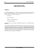
Product Information Guide 2 T217 2500 SET POWER FAILURE 616 EXPANSION UNIT 308 CONTROLLER 24-BUTTON SET MUSIC PUBLIC ADDRESS EXTERNAL ALERTER NETWORK INTERFACE 6-BUTTON SET 217-3 2/87 1 FIGURE 1 - SPIRIT SYSTEM CONFIGURATION AT&T – PROPRIETARY
T217 3 Product Information Guide SYSTEM CONFIGURATION The 308 SPIRIT CS is the smallest configuration; it has up to three CO lines and eight station lines. Adding the optional expansion unit allows growth up to six CO lines and sixteen stations, yielding the 308/616 Spirit system. The model 308 control unit consists of a textured, gray plastic housing and base, enclosing the PWB (printed wiring board) and power supply. The open grillwork on the control unit allows proper system ventilation.
FEATURE CO LINES STATIONS INTERCOM PATHS SPEAKERPHONE CONFERENCE w/DROP SYSTEM SPEEDCALL PERSONAL SPEEDCALL DO NOT DISTURB TRANSFER HFAI/DISABLE STATION MSG ACTIVATION MUSIC-ON-HOLD INTERFACE PAGING INTERFACE PROGRAMMABLE FEATURES IDLE LINE PREFERENCE RINGING LINE PREFERENCE DISTINCTIVE RINGING TOLL RESTRICTION 0/1 restrict allowed list CALL PICKUP NIGHT SERVICE CENTRALIZED ADMIN BRIDGING INDICATION PWR FAILURE OPERATION PWR FAILURE PHONES CUSTOMER INSTALLABLE T217 4 Product Information Guide AT&T SPIRI
5 T217 Product Information Guide SPIRIT COMPETITION The SPIRIT CS faces major competition for small business customers needing an electronic key telephone system. Three companies; TIE, ITT, and TOSHIBA, are top competitors with systems in that communications market. A feature-comparison matrix is shown on the opposite page. SYSTEM DOCUMENTATION A complete set of documentation is included with this package. You will use it as part of your study material, and it is yours to keep for future reference.
Product Information Guide 6 T217 GROUNDING REQUIREMENTS Proper grounding is fundamental as protection against lightning/power surges, power crosses on CO lines, and static discharge to equipment. The green-wire ground of the AC outlet is the only ground serving the SPIRIT system. It must be connected to the building ground. Use the following procedures to verify grounding: 1. Check the AC outlet wiring with an Ideal 61-035 tester or equivalent. The tester comes with instructions. 2.
7 T217 Product Information Guide INSTALLATION The following procedures are required to install a SPIRIT CS, and the customer pays for them in the installation charge: 1. Install the control unit - Special consideration should be given to: ● Local telco CO line terminations (within 25 feet) ● Nearest AC outlet for the control unit (within 6 feet) ● Access for administration, future growth, and changes ● Allowing for proper ventilation (21 inches clearance) ® 2.
8 Product Information Guide T217 SPIRIT WIRING PLAN The SBDS (Small-Business Distribution System) wiring plan for the SPIRIT is the same plan used for the MERLIN CS. The SPIRIT system requires two-pair wiring, but four-pair wiring is used to facilitate migration to four-pair systems in the future. Unlike MERLIN CS control units, SPIRIT control units ship WITHOUT 267C adapters. If these are needed, you must provide them from your supply.
T217 Z601A ADAPTER Z601A ADAPTER Z601A ADAPTER 9 COLOR CODES FOR 4–PR. DIW CABLE OR DW8A-SE CORD COLOR CODES FOR 3–PR. DISTRIBUTION CABLE ( H-STATION WIRE ) COLOR CODES FOR 4–PR. DIW CABLE OR DW8A–SE CORD Product Information Guide 103A, 104A, 105A, 630B CONNECTING BLOCK 103A, 104A, 105A, 630B CONNECTIN6 BLOCK 625, 725, 630B, 830B CONNECTING BLOCK FIGURE 3 - TYPICAL SPIRIT WIRING PLAN AT&T – PROPRIETARY 217–8 3/87 .
10 Product Information Guide T217 CONTROLLER POWER CORD GREEN–WIRE GROUND AC OUTLET ADD SURGE PROTECTOR WHERE APPROPRIATE NETWORK INTERFACE JACK RJ11, RJ14, OR RJ21 D4CH A JACK F1ELLD INSTALLED NEAR YOUR CONTROL UNIT LOCATION JUMPER CORDS PLUGGED INTO THE JACK FIELD AND INTO THE CONTROL UNIT Z122C APPARATUS BOXES W/Z600 SERIES ADAPTERS CABLE EXTENDING FROM THE JACK FIELD TO EACH TELEPHONE LOCATION DW8A CORD 4–PR DIW OR REUSED 25–PR CABLE A MODULAR JACK AT THE END OF EACH CABLE (TELEPHONES WILL B
11 T217 Product Information Guide MODULAR WIRING The method of connection depends on the building wiring termination. Use the following station and distribution wire: ● Tinsel Cord - A 2-pair double-ended modular cord used primarily for sets. ● D-Station Wire - A 22-gauge, two-pair distribution wire. ● H-Station Wire - A 24-gauge, three-pair distribution wire. ● D-Inside Wire - DIW is a 24-gauge, multiple-paired cable.
Product Information Guide 12 NOTES T217
T217 13 Product Information Guide ITEM DESCRIPTION COMCODE 103A-50 258A D2R-29 D2R-29 D2R-29 D4BU-29 D4BU-29 D4BU-29 D4CE-50 DW8A-SE DW8A-SE D8W-87 DIW D-Station H-Station Connecting Block 25-pair to Mod. Adapter Mounting Cord 7 foot Mounting Cord 14 foot Mounting Cord 25 foot Mounting Cord 7 foot Mounting Cord 14 foot Mounting Cord 25 foot Set Extension Cord 50 foot Distribution Cord 100 foot Distribution Cord 200 feet Mounting Cord 2.
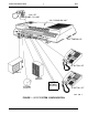
T217 14 Product Information Guide CONTROLLER PAGE SIX–POSITION MODULAR CORD WIRING LABEL 25' RCA–ENDED CORD PAGE INPUT Y CONNECTOR MUSIC IN MALE–MALE RCA–ENDED CORD POWERMATE 25' RCA-ENDED CORD TUNER Y CONNECTOR SPEAKER 217-9 3/87 1 FIGURE 6 - PAGING SYSTEM WIRING AT&T – PROPRIETARY
15 T217 Product Information Guide EXTERNAL PAGING EQUIPMENT The PagePac 1 (for systems with optional public address system) is a loudspeaker paging system with 1-way transmission. Answerback paging is not supported by the SPIRIT CS. Typical hardware provided with the system is a PowerMate amplifier, speakers and wiring. The amplifier connects to the control unit via a 4-conductor, 6-position modular cord. We recommend a direct connection from the control unit whenever possible.
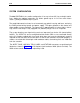
T217 16 Product Information Guide 616 EXPANSION UNIT 308 CONTROLLER BELL 7–FOOT MODULAR CORD ( 4–WIRE ) DCI–48–48 6–POSITION OUTPUT JACK 6–POSITION INPUT JACK 25–FOOT MODULAR CORD ( 4-WIRE ) SUPPLIED WITH ALERTS 6–FOOT POWER CORD AC OUTLET 217-5 3/87 1 FIGURE 7 - EXTERNAL ALERT INTERFACE AT&T – PROPRIETARY
T217 17 Product Information Guide EXTERNAL ALERT The Wheelock DCI-48-48 is an interface unit for powering 48 V DC telephone bells, chimes, horns, strobes, and other external alerts for electronic key systems. The 6-position modular INPUT connects to the control unit ALERT jack while the 6-position OUTPUT connects to the alert device. The DCI-48-48 should be wall-mounted within seven feet of the control unit and within six feet of the AC outlet.
T217 18 Product Information Guide 6–BUTTON SET CS6501 24–BUTTON SET CS6502 217-2 2/87 1 FIGURE 8 - 24-BUTTON MULTIFUNCTION STATION SET AT&T – PROPRIETARY
19 T217 Product Information Guide MULTIFUNCTION STATION SETS The first six buttons on the 6-button and the 24-button sets correspond to the control unit TELCO LINE jacks. Buttons labeled 10 through 25 correspond to the sixteen control unit STATION jacks. These buttons are used for autodialing the 2-digit extension numbers on the 24-button set. The numbers 7, 8, and 9 are omitted, since they have no meaning in the system.
20 Product Information Guide T217 INITIAL SYSTEM TEST Power is applied to the control unit through a line cord plugged into a standard 110 V AC outlet. A lighted green LED, visible in the upper left corner of the control unit, serves as the POWER ON indicator. The control unit software checks all its common hardware immediately after the powerup. At this point, test the CO lines and stations at the controller.
21 T217 Product Information Guide SPEEDCALLlNG All speedcall numbers are assigned a 2-digit dial access code. There are two kinds of speedcall numbers: 1. Personal numbers are assigned by individual station users, and are accessed with digits 10 through 25. Each user may store 16 speedcall numbers. 2. System numbers are stored in the system memory and are accessed by all users. A maximum of 70 system numbers can be assigned; 50 unrestricted and 20 restricted.
Product Information Guide 22 T217 ADMINISTRATION SWITCH POWER INDICATOR OPEN GRILLWORK 616 EXPANSION HEADER 308 CONTROL UNIT 616 CONTROL UNIT 217-4 3/2 1 FIGURE 9 - SYSTEM ADMINISTRATION OVERLAY MODEL 308/616 AT&T – PROPRIETARY
23 T217 Product Information Guide SPIRIT FEATURE ADMINISTRATION The system will function with the assigned default values when power is applied Changes may be administered to system features affecting each CO line appearance or each station set. If choices for programmable features are administered, each feature should be tested to assure proper operation. SPIRIT CS administration may be carried out from either a 6-button or a 24-button set.
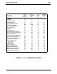
Product Information Guide 24 T217 MANUFACTURER’S DESCRIPTION COMCODE PEC CODE 308 CONTROLLER CNTRL-CS308A1 103985396 6030-308 616 EXPANSION UNIT CNTRL-CS616A1 103985404 60301 6-BUTTON SET SET TEL-CS6501C01A-215 104372339 3130-006 24-BUTTON SET SET TEL-CS6502C01A-215 104372347 3130-024 K2N2-215 HANDSET 103985701 6' HANDCORD H4DU-215 104211305 12' HANDCORD H4DU-215 104211339 EXTERNAL ALERT INTFC 405291568 COMMON DESCRIPTION HANDSET WHEELOCK DCI-48-48 60314 FIGURE 10 - HARDW
T217 25 Product Information Guide SYSTEM MAINTENANCE Read Pages 17 and 18 of the Customer Installation Instructions. You will have a hands-on exercise to try these tests when you attend class. CAUTION: Initiating system self-test interrupts call-processing. Control unit self-tests are made at connector location 10 from the ADMIN mode. Software changes/corrections cannot be made in the field: all software-related problems are cleared by hardware replacement.
26 Product Information Guide T217 WARRANTY AND MAINTENANCE OPTIONS Maintenance options include on-premises service with business-day and 24-hour choices, with depot service as a secondary choice. Maintenance contracts cover the entire system, not just parts of it. During the ONE-YEAR warranty period or the term plan, business-day coverage is included in the purchase or term plan price, and 24-hour coverage, on-premises service is offered as an option.