AT&T ® PagePac Plus System Installation and Configuration Contents General Information - 2 Before You Start - 3 Installation Steps - 4 Connecting Speakers - 9 Power Up System - 12 Self Powered Controller - 13 Troubleshooting - 20 Specifications - 23 Controls and Indicators, Terminals and Connectors - 24 Connectivity Chart - 26 Programming - 28 Quick Reference Charts - 48 Zone Map and Configuration Tables - 51 Application Notes - 57
AT&T463-248-201 0II722051-000 Issue 5, Oct. 1994 Copyright © 1994 Harris Dracon All Rights Reserved Written/Printed in U.S.A. Notice Important Safety Information Every effort was made to ensure that the information in this guide was complete and accurate at the time of printing. However, information is subject to change.
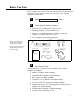
Before You Start Before installing your system, read and understand the safety instructions that follow. Be sure you have all the necessary parts, tools, and test equipment, listed below.
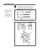
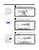
Installation Steps 1 NOTE: When installing the PagePac Plus Controller, leave at least four inches space above and below for proper ventilation. Mount the PagePac Plus Controller and Zone Expansion Units, if any, to either a wall, cabinet or a rack (below the AmpliCenter or other amplifier). SIDE VIEW AMPLICENTER 4" Install the paging equipment in a ventilated room where there is easy access to speaker cabling (preferably in the telephone equipment room).
2 Connect background music input wires to Left and Right terminals if stereo, or, Left and Ground if not. 70V OUT NOTE: The optional audio source can be a CD or tape player, AM, FM, or commercial radio, or other audio device. PAGE IN MUSIC IN AMPLICENTER BACK PANEL LOW FREQ CUT OFF If more than one AmpliCenter is used in the paging system, each one can be connected to the same music source, or different audio device, if desired. MONO OR STEREO Figure 4.
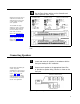
5 Set the AmpliCenter Telephone Mode Selection Switch to Dry Loop 600 Ohms (Far left setting). Figure 7. AmpliCenter Mode Switch Setting 6 NOTE: Up to 3 Zone Expansion Units can be used, providing up to 56 paging and/or control zones. Connect 8-pin Molex from Controller to Zone Expansion Unit(s), if used. CONTROLLER POWER, CONTROL, 70V AUDIO ZONE EXPANSION UNIT #1 POWER, CONTROL, 70V AUDIO TO NEXT ZONE EXPANSION UNIT(S) Figure 8.
8 Make initial sound level adjustments on AmpliCenter. Re-adjust (if necessary) after testing paging system. Using a small standard screwdriver, make the following adjustments. Adjust the Low Frequency Cut Off control to center position. This control cuts out the low frequency bass so that horns and small speakers are not over-driven and distorted by excessive bass energy. Cut-off frequency is continuously adjustable from 50Hz (full CCW rotation) to 400 Hz (full CW rotation).
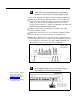
10 NOTE: Depending on the type of host telephone system interface port, the connection may differ slightly from the illustration to the right. A direct 4-conductor cord from the Controller to the telephone system can also be used, bypassing the connector block. Connect cable from host telephone system to Controller Page Input.
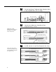
12 NOTE: For each zone used, no matter what its function, this switch needs to be set to one of three settings for proper zone operation. Set the Zone Option switches on the Controller and Zone Expansion Units, if any. SPEAKER SETTING CONTACT CLOSURE OUTPUT CONTACT CLOSURE INPUT 70V AUDIO OUTPUT SHIELDED FOR TALKBACK The Controller has eight switches for zones 1-8. Each subsequent Zone Expansion Unit has switches for zones 9-24, 25-40, and 41-56.
TYPICAL CONNECTIONS FOR CONTROLLER OR ZONE EXPANSION UNITS ZONE CONNECTORS CONTACT CLOSURE OUTPUT CONTACT CLOSURE INPUT DO NOT OVERTIGHTEN SCREW OVER WIRE 70v OUTPUT LABEL ZONE 5 ZONE 6 ZONE1 66 OR 110 TYPE CONNECTOR BLOCK ZONE SWITCH CLOSURE SHIELD TO SPEAKERS OR ZONE CLOSURES ZONE SWITCH CLOSURE INPUT SHIELD SPEAKER ZONES SHIELDED 24 TO 22 AWG WIRE TO CONNECTOR LIMITED NUMBER OF SPEAKERS PER ZONE SCREW LUG TERMINAL BLOCK A LARGER GAUGE WIRE MAY BE REQUIRED FOR HIGH POWER OR VERY LONG CABLE RUNS
ZONE 1 TYPICAL ZONE CONNECTIONS FOR ZONE EXPANSION UNIT CONTACT CLOSURE OUTPUT CONTACT CLOSURE INPUT 70V OUTPUT TERMINAL CONNECTIONS USE 22 TO 24 AWG ZONE 2 DOOR ENTRANCE POWER LOCK MECHANISM OUTPUT-CONTACT CLOSURE (MOMENTARY) INPUT-CONTACT CLOSURE DOORBELL USE TERMINAL BLOCKS AS ILLUSTRATED IN FIGURE 17 WHEN NECESSARY SHIELDED CABLE INPUT-CONTACT CLOSURE 70V ZONE OUTPUT AUDIO WITH TALKBACK LABEL ALL TERMINAL BLOCKS BY ZONE # AND APPLICATION.
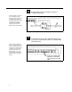
3 Test speaker wiring for short circuits Measure the resistance of each home run wiring with an ohmmeter. Any pair indicating a value of less than 15 ohms must be rechecked for possible shorted wiring or speakers. Correct any problems and retest. 4 Make zone connections to Controller and any Zone Expansion Units. (See Figure 16) The zone connectors on the Controller and Zone Expansion Units can accommodate up to two 22 AWG wires or four 24 AWG wires per zone output.
2 Make an All Zone test page. Re-adjust sound levels, if required. 1. Re-adjust Music Input level to the center desired loudness relative to paging loudness. 2. Some loudspeaker taps may have to be re-adjusted to get even coverage at all locations. Be sure that the final speaker tap setting totals do not exceed the power rating of the AmpliCenter. 3 Begin programming the Controller (page 28).
Controller to Generic Amplifier 1 NOTE: Refer to Tables 1 and 2 for proper audio input requirements and volume control settings. Connect 0dBu or 0dBm output to amplifier audio input. 2 Connect Audio Output (70.7V) to Amplified Audio connector on Controller. 3 Adjust Controller volume control (See table 1) 4 If required, connect control input to amplifier from Controller zone set to “output contact closure.” 5 Connect background music input, if any. 6 Connect host telephone system to Controller.
Table 1. Controller Adjustable Output Levels Controller Volume Control Setting 600 Ohm Impedance Output Low Impedance Output Full Counter Clockwise -12 dBm (195mV rms) -6 dBu (388mV rms) Full Clockwise 0 dBm (.775V rms) +6 dBu (1.5V rms) *NOTE: The generic amplifiers input must be dry, no battery or voltage can be present Condition: -12 dBm on the Telephone Interface or -12 dBu on the Attendant Access input, both outputs are terminated with 600 ohms. Table 2.
Controller to Amplified Speakers 1 Connect 0dBu output from Controller to Amplified Audio input to Controller. 2 Adjust Controller volume control to mid point. 3 Connect amplified speakers to each zone connector. 4 Set zone option switches to Amplified Audio Output. 5 Connect host telephone system to Controller. 6 Plug Power Pack connector into Controller.
Controller to PagePac 20 1 Connect 0dBm un-balanced output from Controller to the modular to spade lug cable (green and red). 2 Adjust Controller volume control to full counter clockwise position. 3 Connect Controller zone contact closure output to the modular to spade lug cable (yellow and black). 4 Plug the 4-connector cable into PagePac 20 “Page Input” and to the modular to spade lug cable. 5 Connect audio output cable from PagePac 20 to Controller Amplified Audio input terminals.
Controller to AmpliCenter 100 1 2 3 Connect the modular to spade lug connector from Controller (To Amp) to amplifier Page In (red and green), and to Music/Page (black and yellow) control. Adjust Controller volume to counter clockwise position. Connect 70V audio out from amplifier to Controller Amplified Audio terminals. 4 Connect host telephone system input to Controller. 5 Plug power pack connector into Controller ADJUST OUTPUT VOLUME CONTROL TO FULL COUNTER CLOCKWISE 16.
Controller to D-Series AmpliCenter 1 2 Connect 6-conductor cord from Controller (To Amp) to AmpliCenter Page Input. Connect 70V audio out from AmpliCenter to Controller Amplified Audio terminals. 3 Connect host telephone system input to Controller. 4 Plug power pack connector into Controller. D-SERIES AMPLICENTER PAGE INTO AMPLIFIER SELF-POWERED CONTROLLER AMPLIFIED AUDIO 16.5 VAC POWER MODULE TO HOST TELEPHONE SYSTEM Figure 22.
Troubleshooting Some common problems encountered when the paging system is not operating are described below. Check each item in the order listed. 1. No AC power to AmpliCenter or Controller 2. Host telephone system failure 3. Host system page port failure 4. A hardwire disconnect between host system and the Controller 5.
Table 3. Troubleshooting (Continued) Corrective Action Problem Talkback feature does not work. Check the zone option switch, make sure that the switch is in the 70 volt position. Check programming options for proper settings. Check the telephone mode switch on the AmpliCenter is set to Dry Loop, 600 ohm mode Noisy Talkback Check the wire to see if shielded cable was used. Change to shielded if necessary. Make sure shield for cable is only tied to the Controller or Zone Expansion Unit end.
Table 3. Troubleshooting (Continued) Problem Corrective Action Relay chatter when Tip and Ring is connected to the Controller Verify that the Telephone Mode Switch on the Controller is set correctly for the host telephone system. A busy signal is returned when attempting to make a page when the Controller is in the Page Port Mode Verify that the Telephone Mode Switch is in the “DL” position to match the host telephone system interface port. Verify Attendant Access is not active.
Controller Specifications Table 6 describes the technical specifications of the Controller. Table 6. Controller Specifications The Controller connects up to 8 zones of audio output (including talkback) and contact closure inputs or outputs. Capacities: ■ Dimensions and Weights ■ Height: ■ Width: 16 inches (40.64) without brackets, 19 inches (48.3 cm) with brackets attached. ■ Depth: 6.875 inches (17.5 cm) ■ Weight: 3 pounds (6.6 kg) 1.75 inches (4.4 cm) Electrical: Voltage: 0.
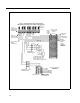
Controls and Indicators, Terminals and Connector Figure 23 shows the controls and indicators, terminals and connectors on the rear panel of the AmpliCenter, Controllers, and Zone Expansion Units. Table 4 identifies them by function. AMPLICENTER CONTROLLER SELF-POWERED CONTROLLER 16.5 VAC POWER MODULE ZONE EXPANSION UNIT Figure 23. AmpliCenter, Controllers, and Zone Expansion Unit Back Panels.
Table 4. Controls and Indicators, Terminals and Connectors 1. AC Power in: 105 – 125 VAC, 210 – 250 VAC, 50/60 Hz. (voltage auto-selectable within unit) 2. 0dBm out, an auxiliary output that differs from the main 70.7V output in that it is a low level (0dB), 600 ohm balanced output used for driving a remote or off-premises amplifier 3. DC Power, and 70V audio out to standard Controller (Not used on self-powered Controller) 4. Bass control screw-type adjustment pot.
Connectivity Chart The Controller Connectivity chart gives the interface requirements for the host telephone systems listed. This information is then used to set the telephone mode function switch on the PagePac Plus Controller. Table 5. PagePac Plus Controller Connectivity Chart Merlin Plus System 2000 Merlin 1030/30/70 Merlin 206/820 Merlin II Merlin Legend Set Mode Switch To: C.O. Line C.O. Line Page Port C.O. Line Page Module C.O. Line Service Module C.O. Line Analog Station C.O.
Comkey 416, 718, 1434 and 2152 Horizon Dimension Set Mode Switch To: C.O. Line Intercom C.O. Line Analog Station Intercom C.O. Line Analog Station Aux. Port Loop Start Yes – Yes – – Yes – – Ground Start* – – Yes – – Yes – – Station Access – – – Yes – – Yes – Ω) Dry Loop (600Ω – – – – – – – Yes Note 7 NOTES: — Indicates a non applicable connection 1.
Programming the Controller The Controller is programmed to enable each zone to have different zone features, if required. There are two ways to do the programming. One is via the RS-232 serial port on the Controller which is connected to a IBM compatible (DOS) PC using the optional programming software. An advantage of using a PC to configure the Controller is that screens can be viewed on the monitor to aid in selecting the zones for various options.
Programming Steps When powered up, the Controller polls the zones to determine how many (if any) Zone Expansion Units are present (see DIP switch settings). The Controller has the capacity to serially access up to 48 external zones. CAUTION: The Zone Option switches must be set before the system is powered up, and therefore before programming commences. NOTE: Programming steps by PC are not described in this guide because the software comes with its own guide.
3 Define Length of ALlAS Numbers This system option allows you to set the length (3 or 4 digits) of the ALlAS number field. The default is 2 digits. If you wish to assign ALlAS numbers to the paging zones, you must set the length parameter. The ALlAS number is the dialing extension for the zone. If no ALIAS numbers are used, the Physical Zone Code is the dialing extension for a zone. This MUST be done before “Zone Map Option – Assigning ALIAS Numbers”, later in this section.
5 NOTE: Your Connect and Programming passwords should not be the same. If this feature is active and the system has been accessed via the telephone interface, then after the first digit of your Programming password is pressed, the dial tone will stop and will not be returned until the correct password is entered or until the user hangs up and re-enters the system. Set Programming Password Establishing a Programming password will restrict access to the programming mode of the PagePac Plus paging system.
7 Turn Pre-Announcement Tone ON/OFF This tone is very similar to the initial talk-back warning tone, in the sense that it is sent to a zone when the zone is accessed. This tone will be sent out to both the zone selected and to the telephone interface. After this tone is sent, you may begin your page message. Default is ON. 1. Dial 4 2 to select this option. Hear a DOUBLE beep. 2. Dial 0 to turn OFF, or 1 to turn ON. Hear TRIPLE beeps. 3.
2. Dial the code to select a duration for the VOX Disconnect Timing: 0 1 2 3 to to to to turn OFF select 10 seconds select 20 seconds select 30 seconds 4 to select 40 seconds 5 to select 50 seconds 6 to select 60 seconds Hear TRIPLE beeps. 3. To verify the duration of the VOX Disconnect Timing, dial 5 1 and repeat step 2 above.
11 Select Input to Computer Monitor This option turns ON or OFF the inputs of Attendant Access, Telephone Access, and Night Bell to be recorded and displayed by the Computer Monitor if you have activated it in Step 10. Default is OFF for all three. You will repeat this procedure 3 times in order to reset all three inputs. 1. Dial 5 4 to select this option. Hear a DOUBLE beep. 2.
13 Set Supervised Trunk Mode If the host telephone system is not a Merlin Legend this feature does not apply. Proceed to Step 14. NOTE: Once the option has been configured, you should place the Controller Telephone Mode switch to the Ground Start position. Connect the telephone interface to a Loop Start trunk on the host system using a standard two-conductor (not four-conductor) RJ-11 cable.
15 Inhibit Dial Tone Detect Supervision of the Station/Centrex Access mode is accomplished in 3 ways, by monitoring the loop current and the audio signal (including dial tone), and a forced disconnect timer. This option (only applicable in the station access mode) enables you to defeat the dial tone detect function in order to send a tone via the Telephone Interface to the output. 1. Dial 2 4 to select this option Hear a DOUBLE beep. 2. Dial 0 to turn Enable, or 1 to turn Inhibit Hear TRIPLE beeps. 3.
16 NOTE: Before doing this option, you MUST do “Define Length of ALIAS Numbers” (see Step 3). Zone Map Option—Assigning ALlAS Numbers Zone Map permits you to assign the dialing code, called the ALlAS zone code, that you will dial to access a particular zone by telephone (i.e., instead of dialing 02 to make a page, you could dial 2202). The factory default is NONE: no ALlAS numbers are pre-programmed.
3. Press 0 to designate the zone as OUTPUT Press 1 to designate it as INPUT #1, or Press 2 to designate it as INPUT #2 Hear TRIPLE beeps. 4. To verify the zone type assignment, dial 6 3 and repeat steps 2 and 3 above. 18 Set Input Priority Arrangement The input priorities are pre-set at the factory. You may only assign a priority level to inputs such as doorbell or security alarm, by assigning them to Input #1 or Input #2, which differ in priority. NOTE: These priorities cannot be rearranged.
20 Set Zone Grouping to Page This option allows you to select a group of zones to be paged at the same time. The number of zone groups that can be formulated is eight; the maximum number of zones per group is 56 zones. The factory default is NONE (there are no default zone groups). You will need to repeat this procedure for each zone group you wish to set up. 1. Dial 6 4 to select this option. Hear a DOUBLE beep. 2. Enter the zone code, of the zone group to be defined (81 thru 88).
21 Set Output Zone Type This option selects the type of output for an individual output zone. The choices here are Audio/Normally Open, Normally Closed, System Handshake, Momentary Open, Toggle, Phantom, and Attendant Access Handshake. The Audio/Normally Open option is the default. The primary use for the Normally Closed Or System Handshake is to determine how the switch closure is to function.
22 NOTE: If you make an all-call page and this option is selected NO in either a Zone Group or Individual Zones, then an all-call page will be made to all other zones except the ones specified. If the decision is NO for the All-Call zone and an all-call page is made, then an error tone will be returned to you. NOTE: Use ALIAS numbers, if optioned. Otherwise, use Physical zone/group numbers. Set Page Enable This output zone parameter enables paging for a selected output zone or zone group.
1. Dial 7 6 to select this option. Hear a DOUBLE beep. 2. Enter the zone or group zone number. NOTE: Use ALIAS numbers, if optioned. Otherwise, use Physical zone/group numbers. Hear a DOUBLE beep. 3. Enter 0 for NO (Not Enabled) or 1 for YES (Enabled) Hear TRIPLE beeps. 4. To verify the status of Talk-Back Enable for a given zone, dial and repeat steps 2 and 3 above. 25 Set Night Bell Enable This is an individual zone output parameter. The choice is YES/NO with the default being NO.
26 Pass DTMF to the Output This zone output option enables the Touchtone telephone keypad tones (DTMF) to be passed through the Controller and output to a second controller or other ancillary device. The choice is YES/NO, with the default being NO. Operating the unit in the default mode, you may switch from zone to zone (within the same Controller) without hanging up, simply by dialing the zone number of the zone you wish to switch to.
Input Zone / Group Options These options apply to zones or groups already configured as inputs (see “Type of Zone,” Step 17). These options are summarized in the Programming Quick Reference Chart, at the end of this section. 27 Tone Selection If a zone is configured to be an input and is activated, then a tone may be selected to be directed to whatever zone(s) are selected in “Tone Routing,” below. The tone selections are listed in step 3.
Description of Tones Dial tone: continuous, like the dial tone of a telephone system Confirmation tone: three beeps Pre-Announcement tone: 1.5 second duration, 440 Hz Talk-back Warning tone: 1.
1. Dial 9 6 to select Audio Source Enable. Hear a DOUBLE beep. 2. Enter the input zone or group number. Use ALIAS numbers, if optioned. Otherwise, use Physical zone/group numbers. Hear a DOUBLE beep. 3. Enter 0 (NONE), 1 (AA, Attendant Access), or 2 (T/R, Telephone Access) to select the audio source (or none) to be enabled when this zone is activated. Hear TRIPLE beeps. 4. To verify your selection, Dial 9 7 and repeat steps 2 and 3, above.
Error Tones The Error Tone is heard over the phone receiver when an incorrect zone number has been dialed or contradictory programming input has been attempted. Hear error tone when dialing a zone ALlAS number When a zone is selected by Touchtone telephone keypad input (DTMF), the PagePac Plus searches for the zone in numerical order of the physical zones; the value dialed (the ALlAS number) is then compared to the digits stored in memory for each physical zone.
Programming Quick Reference Chart Chart 1. System Configuration Options Feature Mode Option/ Verify Dial Listen For Choose Option Listen For Default Reset to Factory Defaults To Select 10 Double Beep Enter 25327 to reset. Enter any invalid number string to escape. Triple Beeps 25327 (CLEAR) Number of Zone Map Digits To Select To Verify 20 21 Double 3 (digits) 4 (digits) Triple Beeps 2 To Select To Verify 30 31 Double Beep Enter Password, enter terminate the string.
Chart 2. General Zone / Group Configurations Feature Mode Option/ Verify Dial Listen For Zone/Group Selection Listen For Zone Map To Select To Verify 60 61 Double Beep Enter physical zone/group number. Double Beep Triple Beeps Enter alias zone/group number. Type of Zone To Select To Verify 62 63 Double Beep Enter zone/group number. Double Beep 0 – Output 1 – Input 1 2 – Input 2 Zone Grouping To Select To Verify 64 65 Double Enter group number.
Chart 4. Input Zone / Group Configurations Modify Option/ Verify Dial Listen For Zone/Group Selection Listen For Choose Option Listen For Default Activate Tone via an Imput Closure To Select To Verify 92 93 Double Enter the input zone number. Double Beep 0 – None 1 – Chime 2 – Siren 3 – Warble Siren 4 – Night Bell 5 – Fast Ring 6 – Steady Tone 7 – Door Bell Triple Beeps None Beep Tone Routing To Select To Verify 94 95 Double Beep Enter the input zone number.
Zone Map and Zone Configuration Tables The Zone Map (table 7) assists in identifying each zone, both input and output, of your particular paging layout. The Zone Configuration table (table 8) identifies each input and output zone, and their associated features. Refer to your facilities floor plan. With these three tables filled out, programming can begin. NOTE: You may find it helpful to photocopy the tables and fill the copies out.
8 Enter the Priority Level (1 or 2) for this zone Priority Level 1 inputs are “first in” to access the page 9 Select Tone 1 - 7 for this zone See Tone Selection descriptions on page 44. 10 Enter the Zone or Group Zone to receive the tone. Refer to Zone map to determine what zones will hear this tone. 11 Enter 0, 1, or 2 for Audio Enable to this zone. 0 = None, 1 = AA, Attendant Access, and 2 = T/R Telephone Access. Refer to Audio Enable on page 46.
Table 7.
Table 7.
Table 8. Zone Configuration Table (Output Zones) DESCRIPTION OF OUTPUT ZONE Phys. Zone Code Type of Output Page Music Talkback Night Bell DTMF Pass Enable Y/N Enable Y/N Enable Y/N Enable Y/N thru Y/N Example i.e.
Table 8. Zone Configuration Table (Input Zones) DESCRIPTION OF INPUT ZONE Priority Physical Zone Select Tone 1-7 Code Level 1 or 2 Route Tone to Zone Audio Enable 0-2 Audio Route to Zone 81 2 05 Examples i.e.
Application Notes Night Bell There are two different Night Bell connections possible to the Controller. These are illustrated in figure 24. From an EKTS Telephone System A programmer needs to know what type of Night Bell connection exists between the telephone system and the Controller.
Door and Speaker Control Visitor Presses Doorbell Figure 25 illustrates door speaker and control interfaces. When a visitor presses the doorbell of a security door, a contact-closure input to the controller signals an output tone (i.e., a door chime) to selected paging zone(s).
If the doorbell input has a higher priority than T/A (i.e., is Input #1), and is activated while T/A paging is in progress, or during a dial tone, then the user will hear the door chime tone and be automatically routed to the door speaker for two-way communication.
Computer Monitor and Visual Message Display Figure 27 illustrates the Computer Monitor and Visual Display interface. If a PC computer is connected to the RS-232 port of the Controller for the purpose of logging paging activities, you will need to program the Controller to send signals to it, and turn ON/OFF the Attendant Access, Telephone Access, and Night Bell signals that would trigger the monitor to log the event.
Talkback Any audio output zone can be programmed for Talkback. Each Talkback paging zone must use shielded cable, grounded at the Controller zone connector, not the speaker. All speakers in a zone will be two-way speakers, if talkback has been enabled for a zone. Therefore all speakers in the talkback zone will pick up ambient noise, as well as the voices of persons addressing the paging speakers.
AMPLICENTER PAGE INPUT CONTROLLER CONTACT CLOSURE OUTPUT (BLK/YEL) TO AMP 0dBm OUTPUT (RED/GRN) REMOTE AMPLICENTER PAGE INPUT REMOTE PAGING SYSTEM AMPLICENTER PAGE INPUT CONTROLLER TO AMP Figure 28.
© 1994 AT&T All rights reserved Printed in U.S.A.