AT&T SPIRIT ® Communications System SPIRIT Attendant Installer’s Guide
SPIRIT is a registered trademark of AT&T. Copyright © 1991 by AT&T All Rights Reserved Printed in the United States of America Document Order No. 518-453-711 April 1991 Issue 1 Notice: The information in this document is subject to change without notice. AT&T assumes no responsibility for any errors that may appear in this document.
Contents Section 1: Installation Requirements Overview Equipment and Location Requirements Administration Procedures Connecting the SPIRIT Attendant 1-1 1-5 1-7 1-8 Section 2: Initial Programming Programming Features 2-1 Section 3: Testing and Troubleshooting Testing Troubleshooting 3-1 3-2 Index IN-1 Index
List of Tables Table Page 1-1 1-2 1-3 1-4 1-5 Meaning of Power and Battery Lights Meaning of Setup Switch Settings Calls Per Hour Table Incoming Lines Table Switch Settings When Operating Unit 1-2 1-3 1-5 1-6 1-10 2-1 2-2 Announcement Time Allocations Call Processing Options 2-4 2-10 3-1 3-2 Out-of-Service Codes Pinout Assignment For the TI 700 or AT&T 475 Printer 3-3 3-5
List of Figures Figure Page 1-1 1-2 1-3 1-4 Front View of the SPIRIT Attendant Back View of the SPIRIT Attendant Setup Switch Positions for Installing Unit Connecting two SPIRIT Attendants 1-2 1-3 1-9 1-11 2-1 2-2 Blind Transfer Process Immediate and Backup Call Handling 2-7 2-8
FCC Notification Information Interference Information Federal Communications Commission (FCC) Rules require that you be notified of the following: ● ● ● ● ● This equipment generates, uses, and can radiate radio frequency energy and, if not installed and used in accordance with the instructions in this manual, may cause interference to radio communications.
Section 1: Installation Requirements
Overview The SPIRIT Attendant answers incoming calls on designated lines with a prerecorded message and directs callers to the appropriate extension in the SPIRIT Communications System.
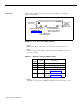
Front Panel There are three lights on the front panel as shown in Figure 1-1. The lights indicate the following: Lights when ac power is on Attendant AT& T power Blinking light indicates a problem. See "Troubleshooting" battery taking Lights when SPIRIT Attendant answers and monitors calls Steady light indicates battery is fully charged (when power light is on) Light off when battery is not fully charged FIGURE 1-l. Front View of the SPIRIT Attendant.
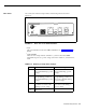
Back Panel The connectors and four setup switches on the back panel are shown in Figure 1-2. AT&T audio off on reset FIGURE 1-2. ● ● setup 10VAC serial i/o out reserved to line Back View of the SPIRIT Attendant. reset This recessed button resets the SPIRIT Attendant. See "Troubleshooting" for details. setup switches There are four setup switches. Switches 1, 2, and 3 control the SPIRIT Attendant response to a power outage as shown in Table 1-2; switch 4 is not used. TABLE 1-2.
CAUTION: After connecting ac power to the SPIRIT Attendant, be sure that switches 1 and 2 are on (down). With this setting, recorded announcements are saved up to three hours during a power outage (if the battery is fully charged) and routing plans and programming parameters are retained up to eight weeks. ● ● ● ● ● 1-4 Installation Requirements 10 VAC This is the power connection. serial i/o This is the connection for the printer to perform diagnostic tests.
Equipment and Location Requirements The following equipment is supplied with the SPIRIT Attendant: ● Power cord with transformer ● 8-foot, 4-wire modular phone cord ● Mounting plate ● User’s Guide ● SPIRIT Attendant ConnecT/R (118B) The 118B must be connected to a station port in the SPIRIT system control unit. Up to four SPIRIT Attendant units (connected to four 118Bs) can be connected to the system.
TABLE 1-4. Incoming Lines Table. Number of Lines Number of Units Needed 3 or fewer 1 4-6 2 6-8 3 8 - 10 4 The number of units needed can also be affected by the type of calls a customer receives. If there is significant overflow of unanswered calls to the receptionist, an additional SPIRIT Attendant may be needed.
Administration Procedures Before installing a SPIRIT Attendant, you must install and administer a SPIRIT Attendant ConnecT/R (118B) for each unit you are connecting. Perform all the appropriate administration procedures from a SPIRIT system telephone that is connected to the SPIRIT system control unit. (Refer to the SPIRIT Administration Manual.
Install a ConnecT/R (118A) with an alerter (such as AUXILIARY TONE RINGER Comcode 105446546) connected to the TEL-DEVICE connector. Program a route in the SPIRIT Attendant to transfer all calls intended for the parts department to the extension number of the station port where the alerter is connected. Any of the personnel in the parts department can access the incoming call that is alerting by pressing “INTERCOM ✳ 8 XX”, where the XX is the extension number of the common alerter.
Connecting the SPIRIT Attendant CAUTION: Before initial installation of the SPIRIT Attendant, set switches 1 and 2 on the back panel to off (up). Follow the steps below to install the SPIRIT Attendant: FIGURE 1-3. Setup Switch Positions for Installing Unit. 1. For each SPIRIT Attendant port: a. Install a SPIRIT Attendant ConnecT/R (118B) on the SPIRIT system control unit. 2. Place the SPIRIT Attendant on a table or desktop, or mount it using the mounting bracket: a.
5. Plug one end of the power cord into the 10 VAC power connection on the SPIRIT Attendant. 6. Plug the other end into a 120 VAC outlet. The power light goes on. If the battery light flashes, announcements have not been programmed. (For a complete description of error codes, see Table 3-1 on page 3-3.) 7. Reset the setup switches as described in Table 1-5. TABLE 1-5. Switch Settings When Operating Unit.
SPIRIT Controller Station Ports SPIRIT Attendant ConnecT/R 118B SPIRIT Attendant FIGURE 1-4. Connecting two SPIRIT Attendants. Using an Answering Machine If the customer is using an answering machine to cover a station, the answering machine must be set to answer in less than four rings.
Section 2: Initial Programming
Programming Features The SPIRIT Attendant is programmed from a Touch-Tone phone using special command strings that are discussed in this section. For each command string: ✳ tells the SPIRIT Attendant that the following digits are a part of a command string. It can also be used to start a command over when a mistake is made. # denotes the end of an entry or executes the command string. Completing the Planning Configurator Form Ask the customer for the completed SPIRIT Attendant Planning Configurator Form.
= = = = = = 2 3 4 5 6 7 Monday Tuesday Wednesday Thursday Friday Saturday b. Two digits for the current month 01 02 03 04 05 06 07 08 09 10 11 12 = = = = = = = = = = = = January February March April May June July August September October November December c. Two digits for the current date (01 - 31) d. Two digits for the current year (00 - 99) e. Two digits for the current hour (in military time) 00 23 = = midnight 11:00 p.m. f. Two digits for the current minute (00 - 59) g.
= = = = = 3 4 5 6 7 2. Tuesday Wednesday Thursday Friday Saturday Dial one digit to indicate whether the business is open or closed for the day specified in step 1. 1 2 3 = = = open closed holiday The two-beep confirmation tone sounds. Setting the Business Hours 3. Repeat steps 1 and 2 for each day of the week (unless the business is open the entire week). 4. Continue programming or dial ✳ # to exit authorized caller mode. 5. Dial # again to disconnect.
2. Repeat step 1 for each day (unless “entire week” is selected). 3. Continue programming or dial ✳ # to exit authorized caller mode. 4. Reallocating Announcement Times To disconnect, dial #. Three announcements are available. Each has a duration in seconds, totaling 64 seconds. The customer can elect to lengthen or shorten any of the time allocations, as long as the total equals 64 seconds. If a customer is not using an announcement, set the allocated time to 00.
2. Dial # to enter the command. The two-beep confirmation tone sounds. 3. Continue programming or dial ✳ # to exit authorized caller mode. 4. Dial # to disconnect. Recording Announcements The customer may elect to record these announcements in his or her own voice or the voice of another employee.
Playing Back Announcements To confirm the recording of announcements, use the following procedure: 1. Dial ✳ 5 followed by the appropriate announcement code: 1 2 4 = = = Day announcement Night announcement Hold announcement You hear the announcement as it was recorded. 2. Repeat steps 1 and 2 for each announcement. 3. Continue programming or dial ✳ # to exit authorized caller mode. 4. Determining the Routing Plan Dial # to disconnect.
SPIRIT Attendant answers call. Caller enters route or extension number. No Caller's first time hearing message? Yes Call is transferred to receptionist; SPIRIT Attendant disconnects. No Disconnect. Yes Route valid? Yes Extension valid? Call transferred to extension; SPIRIT Attendant disconnects. Route answers. Extension answers. Yes Programming Call Handling Options Call is transferred to station assigned to route matching first digit of extension dialed.
Central office lines SPIRIT System control unit SPIRIT Attendant Receptionist Overflow SPIRIT Attendant is Immediate Call Handler - Calls ring immediately at the SPIRIT Attendant. If not answered within a specified number of rings, calls will ring at the receptionist. Central office lines SPIRIT System control unit SPIRIT Attendant Receptionist Overflow SPIRIT Attendant is Backup Call Handler - Calls ring immediately at the receptionist.
11 21 Changing Call Processing Options = = Day Route Night Route 4. Dial 2 for a blind transfer or 5 for disconnect. 5. Dial the extension number where the caller will be connected. 6. Dial # #. 7. Continue programming or dial ✳ # to exit authorized caller mode. 8. Dial # to disconnect. This section contains a list of ringing options and time delays that can be adjusted depending on the customer’s needs.
TABLE 2-2. Call Processing Options. Option/ Description Program Code Default Setting Possible Settings 2901 Day Answer Delay In Day mode, number of rings before the SPIRIT Attendant answers an incoming call. Set to 1 for immediate call handling. 1 1 – 25* 2902 Night Answer Delay In Night mode, number of rings before the SPIRIT Attendant answers an incoming call. Determines immediate or backup call handling. If not using Night mode, set to 15.
4. Dial ✳ followed by “Program Code” shown on Table 2-2. 2901 2902 2903 9709 9710 = = = = = Day Answer Delay Night Answer Delay Dialing Delay Lowest Extension Highest Extension 5. Dial the number you have entered under “Current Setting.” 6. Dial #. The two-beep confirmation tone sounds. NOTE: For Codes 9709 (Lowest Extension) and 9710 (Highest Extension), dial the pound sign (#) two times to enter. (# #) 7. Continue programming or exit authorized caller mode by dialing ✳ #. 8.
Section 3: Testing and Troubleshooting
Testing Once you have installed and programmed the SPIRIT Attendant, you should dial the SPIRIT Attendant from a Touch-Tone phone and perform the following tests: Testing Routes Use this procedure to test the customer’s routes: 1. Dial the first route number. 2. Use the customer’s route plan to verify that the correct extension rings. Do not pick up the call. 3. Make sure the unanswered call is returned to the SPIRIT Attendant. 4. Repeat this procedure for each of the routes.
Troubleshooting Out-of-Service Codes If the SPIRIT Attendant detects a problem, the unit enters an out-of-service state. The LED labeled “battery” on the front panel blinks a specific number of times, pauses, then repeats the pattern. Refer to Table 3-1 for a list of the Out-of-Service codes. NOTE: The SPIRIT Attendant will not answer calls while it is out of service. The line will continue to ring until the caller hangs up.
TABLE 3-1. Number of Blinks Power Failures Out-of-Service Codes. Problem 1 Announcements were not recorded or were erased (slow blink) or cannot compute battery level (fast blink). 2 Unable to turn Voice Recorder off. 3 Unable to turn Voice Recorder on. 4 Unable to turn Voice Playback off. 5 Unable to turn Voice Playback on. 6 Announcement detected with no time allocation. 7 Attempt made to play an unrecorded announcement. 8 RAM constants pool corruption detected.
Printing Reports You can connect a TI 700 or equivalent 1200-baud serial printer to the serial i/o port of the SPIRIT Attendant to produce reports to analyze call traffic patterns or to see how routes, announcement times, or business schedules are programmed. NOTE: Setting the Baud Rate A special adapter (printer cable) is required to connect a “silent 700” printer. The default baud rate for the serial i/o port is 9600.
Connecting the Printer To connect the printer, you need the following equipment: ● ● 14-foot, 8-conductor modular cable (straight). Modular/RS-232 DB-25 adapter, male connector or Modular/RS-232 DB-25 adapter, female connector (depending on printer model). The cable must be configured as shown in Table 3-2. TABLE 3-2. Pinout Assignment for the TI 700 or AT&T 475 Printer.
Using a TI 700 Printer There are two sets of switch settings to check on TI 700 printers.
5. Exit authorized caller mode by dialing ✳ #. 6. Printing Call Processing Reports To disconnect, dial #. To print the current settings of call processing options, perform the following steps: 1. Select an outside line and dial a telephone number that is answered by the SPIRIT Attendant. 2. Wait for an answer. 3. Dial ✳ followed immediately by the authorized caller code and #. 4.
Callers Disconnected After Greeting If incoming callers hear the SPIRIT Attendant greeting and then are disconnected instead of being transferred, one or more greetings may not have been recorded. In this situation, the SPIRIT Attendant sounds a warning beep that no message exists. This beep (generated by a Touch-Tone star sign) causes the SPIRIT Attendant to ignore any following Touch-Tone characters entered by the caller. To verify that this is the case: 1.
Index 10 VAC, 1-4 355A adapter, 3-4 6-wire modular phone cord, 1-5 A Abandoned calls, 3-4, 3-8 AC power, 1-2, 3-2 disconnecting, 1-4 C Calendar, 1-1 weekly, 1-1 Call handling, 2-7 backup, 2-7 immediate, 2-7 changing, 2-9 to 2-11 printing, 3-7 After-hours call handling, 1-1, 1-5 Call processing improving, 2-9 Announcement times reallocating, 2-1 Call traffic patterns analyzing, 3-4 Announcement, 2-10 recording, 2-5 Announcements, 1-1, 2-1, 3-2 erased, 1-3 loss of, 1-3 lost, 3-7 maintained during powe
power, 1-2 talking, 1-2 Day mode, 2-10 Day route, 2-9 Default authorized caller code, 2-1 Lost authorized caller code, 3-7 Lowest extension, 2-10 M Default business days, 2-2 SPIRIT system settings, 3-7 Macro code, 2-1 Diagnostic tests, 1-4, 3-1 Modular phone cord, 1-5 Dialing delay, 2-10 Disconnected callers, 3-8 Mounting plate, 1-5 N Disconnecting AC power, 1-4 Night announcement allocating time for, 1-1, 2-4 using, 2-1 E Extension numbers testing, 3-1 Night answer delay, 2-10 Extension inval
Security code, 1-1 Selecting announcement durations, 2-4 to 2-5 T1 700, 1-4 traffic analysis report, 3-6 Printing call processing reports, 3-7 Programming blind transfer routes, 2-9 Programming mode entering, 2-1 leaving, 2-2 Programming routes, 2-8 Programming from remote location, 1-1 maintained during power outage, 3-3 on-site, 1-1 remote, 1-1 R Real-time clock, 3-3 Receptionist, 1-1, 2-10, 2-6, 2-7, 3-8 Recorded announcements, 1-1, 3-2 power failures, 2-5, 3-3 Remote programming, 1-1 Serial i/o, 1-4,
User’s Guide, 1-5 V Voice playback, 3-3 Voice recorder, 3-3 IN-4
AT&T 518-453-711 Issue 1 April 1991 Graphics © AT&T 1988