AT&T Security System 8300 Installer’s Manual Issue 1.
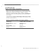
CCU Main Board and Display Control Keypad Compatibility Only the enhanced Display Control Keypad can be used with the enhanced CCU Main Board. The enhanced CCU Main Board and the enhanced Display Control Keypad provide expanded Listen-In/Talk-Back capabilities, described in Appendix D Listen-In/Talk-Back. Table 0-1 describes compatibility between the two different versions of the CCU Main Board and the two different Display Control Keypads.
THIS MODEL 8300 CMP1 CIRCUIT PACK MUST BE USED WITH THE MODEL 8345 DISPLAY KEYPAD WITH COMCODE 106776164 AND SKU36010 Figure O-l. CCU Main Board I / THIS MODEL 8345 DISPLAY KEYPAD WITH COMCODE NUMBER 106776164 AND SKU36010 MUST BE USED WITH MODEL 8300 CMP1 Figure O-2.
Contents 1 Introduction 1-1 . . 1-1 . .
. . . . 3 2-6 2-6 2-6 2-9 2-9 2-10 2-10 2-l 1 2-12 2-12 2-12 2-15 Programming the System 3-1 . . . . . 3-l 3-l 3-2 3-5 3-8 3-8 3-9 3-11 3-23 3-24 3-25 3-25 3-26 3-26 3-28 3-29 3-30 . . . . .
Start-Up, Testing, and Troubleshooting . . 5 !\ - Initial Testing Siren Test Relay Test X-l 0 Test Verification Test Troubleshooting 4-l 4-l 4-1 4-l 4-l 4-2 4-3 Operations 5-1 . . . . . . . . . . . . . . . . .
A B Wireless Considerations A-I . . . . . . A-l A-l A-l A-2 A-3 A-3 A-3 A-5 A-5 A-0 A-10 A-13 Unique Sensor Identification Using Extension Codes . . . .
. L C Forms C-l . . . . .
Figures 1 Introduction l-l l-2 l-3 l-4 l-5 l-6 l-7 System Diagram Display Control Keypad Control Keypad Wireless Remote/Transmitter Wireless Smoke Detector Wireless PIR Universal Wireless Transmitter l-2 l-4 l-4 l-5 1-5 l-6 l-6 Installation 2-l Non-UL Wiring Options 2-2 Open Loop (Fn#515 = 1) 2-3 Closed Loop (Fn#515 = 0) 2-4 Suggested System for UL Residential Local Fire (UL#985), Burglary (UL#1023), and Medical (UL#1637)-See Notes 2-5 Suggested System for UL Commercial Burglary (UL#1610, 1635, 609, an
2-16 Open Loop Keyswitch 2-l 7 Hardwired Smoke Detectors 2-18 UL Bell Wiring 2-23 2-24 2-25 Programming the System 3-3 3-1 Entering Letters and Numbers 3-2 Function Numbers Visualized as a “Grid” to Fill Out 3-4 3-5 3-3 Keypad Button Functions 3-6 3-4 Moving Through the Grid 3-7 3-4 Moving Through the Grid (cont’d.
Tables 2 Installation 2-l 2-2 2-3 2-4 2-5 2-6 3 Residential UL Listings Commercial UL Listings Power Drain for System Components Possible System Configurations Power Usage versus Alarm Times How To Eliminate Sounds Programming the System 3-l UL Programming Requirements 3-2 Programming Defaults, Categories versus Response Type (Fn# 411-414) 3-3 SIA Message Format 3-4 Compatibility with Commonly Used Monitoring Service Receivers B 3-24 3-25 3-28 3-30 Unique Sensor Identification Using Extension Codes
Introduction Introduction This introduction contains the initial information that you will want to study during your first exposure to the AT&T Security System 8300, and may wish to review occasionally thereafter. It is meant to provide an overall understanding (the “big picture”) that will help you use the AT&T devices and the information that is presented in the following chapters of this manual.
Note 1 er .. .. .. ... = = Note 2 1 Display/Control keypad (8340) Note 3 l 1 Control keypad (6345) or 8340 Up to 6 additional 6340 _ and/or 6345 ---------I I 0 tional | 8301 Software Package , and Computer I I Communications Control Unit (CCU) - Keypad. Expansion Module (( 6561 Passive Wireless Receiver Module 6325 (Opt.
the Installer) and “Police” alarms. The “Display” version of the Control Keypads (explained in the following sections) also has both telephone and intercom capability built in; it also has a liquid crystal (text) display to help with programming, show status, and indicate the type and location of trouble and alarms. A third type of control is the Wireless Remote/ Transmitter keypad.
Display Control Keypad (Model 8345) The Display Control Keypad (see Figure l-2) is the primary way of communicating with the CCU, and at least one of them is required for every system. Up to 8 keypads (maximum of 5 of them Display type) may be used in a single system (maximum of 4 for UL Listed systems). The dealer/installer can completely program the System 8300 through the Display Control Keypad; the user can perform the User-Level programming operations with it.
Hardwired Zone Sensors System 8300 accepts up to sixteen hardwired zones. As with all hardwired zones, no sensor in any one zone can be differentiated from any other. Hardwired zone sensors offer a convenient and inexpensive way to provide a single type of protection for a large area, using a large number of sensors without the cost and complexity of identifying and treating each sensor separately. Supervision is by end-of-line resistor.
As the battery voltage begins to get low, the device itself will begin to beep about every fourteen seconds. If this does not result in the batteries being replaced within a reasonable time, the smoke detector’s transmitter will send a low battery signal to the CCU. This second warning occurs with at least seven days of normal operation left, allowing Dealer or User to replace the battery without loss of protection.
Other Devices In addition to the previously mentioned devices, your system might include: n . n Special sensors or switches (connected to a universal wireless transmitter or hardwired zone): audio discriminators, mechanical glass break sensors, temperature and ionization sensors, all types of reed switches. Must be UL listed for UL listed installations. Sirens or horns which fit the systems electrical specifications.
Installation The Basic Process The two primary System 8300 installation operations are “programming” and the physical installation, You must decide whether to do much of the programming before the actual installation or leave it all until after. During programming you supply considerable information and instructions to the CCU, to take advantage of the system’s great flexibility. Chapter 3 covers this process in depth.
Basic Installation Guidelines 1. Plan or review the installation. 2. You may choose to program the CCU at your workbench before going to the site. You can do all programming (except for Fn#519, mentioned above), or enter only the information that is considered firm. This can be accomplished quite easily with the optional computer program, CCUBOSS. 3. Refer to the Appendix for other wireless considerations. This will help reception considerably. b.
-- 17. Verify that system operates properly in each Level of Protection (OFF, DAY, NIGHT, and AWAY) by setting the system to that Level and actually verifying responses. Wiring Data 1. Use Earth Ground for the CCU except in UL listed Residential Fire applications. The preferred ground is an 8 foot copper clad ground rod located close to the power and telephone ground rods, and electrically connected to each. Conductive metal cold water pipe may constitute a valid earth ground.
Open contacts, no CCU Terminal’ Break in circuit I I LJ 1 PHONE WIRE TWISTED PAIR Close conducts or short across circuit produces ALARM 1000 ohm End-of-Line Resistor Figure 2-2 Open Loop (Fn#515 = 1) 7. PHONE WIRE TWISTED PAIR Hardwire smoke detectors requiring interruptible power can be wired with power directly from the INT PWR and GND terminals for low power (75 mA maximum) applications, other options are included later in this section under Hardwired Smoke Detectors.
Residential UL Requirements Table 2-l Residential UL Listings Type of Application Residential Burglary Governing UL Standard UL1023 Residential Fire (local alarm) UL985 Residential Fire plus Burglary UL1023, UL985 Residential Medical UL1637 Required Auxiliary Equip UL Listed Horn (Wheelock, EH-EL2-WI) UL Listed Smoke Detector (ESL, 445A or 445AT) plus Power Supv. Relay (ESL, 204A) UL Listed Horn (Wheelock, EH-EL2-WI) UL Listed Smoke Detector (ESL, 445A or 445AT) plus Power Supv.
Commercial UL Requirements Table 2-2 Commercial UL Listings Type of Application Commercial Burglary (Central Station Grade C) Governing UL Standard UL1610 with UL1635 Commercial Burglary (Central Station Grade B) UL1610, UL1635 for UL 163.
\ \ MAIN BOARD (Not to scale) PHONE BLOCK MONITOR JUMPER 1 / 3 1 1 1 LITHIUM BATTERY JUMPER Move jumper to ON (left) to enable battery support of systems memory. If not enabled, shut down or removal of power will cause loss of program. k ON 0 ON HARDWIRE ZONE CONNECTORS Each numbered zone has a terminal with that number. Next to each is a GND terminal for the return wire. Up to two 22 gauge wires may be connected to any ground terminal.
LOW AC Connect these power inputs from the transformer to these 2 terminal. AUX PWR+, AUX PWRConnect devices requiring 1 O-1 5 VDC, (400ma total current) power here. 1 1 1 1 SIR1-, SIREN1&2+, SIR2Connect the (-) siren 1 lead to SIR1and the (t) to either SlREN1&2+. Do the same way for siren 2. See UL Note 2 R1 COM Relay 1 terminal connecting to the common for the relays Open and Closed contacts. R1 NC Relay 1 terminal to the contacts that are closed except when the relay is energized. 1 ampere rating.
Battery and Power Supply Considerations and peripheral devices that are powered from the System. Calculate to see if the standard power supply and battery are adequate for your needs, Steady State Current Drain NOTE: Where conflicts appear with UL requirements, be sure to use only the UL ratings for any UL Listed installation. Use Table 2-3 to calculate your system’s current drain.
Table 2-4 Possible System Configurations Maximum No. of Keypads Max Siren Current UL Listed? Maximum Siren Time 4 0.5 Unlimited Yes 4 1.0 60 minutes Yes 4 1.5 30 minutes No 3 Display + 2 Control 1.5 30 minutes No 3 Display + 2 Control 1.0 60 minutes No 2 Display + 4 Control 1.5 30 minutes No 2 Display + 4 Control 1 .o 60 minutes No 6 any combination 1.0 30 minutes No 8 any combination 1 .0 x 2N”‘“’ 30 minutes No 8 any combination 1.
Typical Standby Battery Life This figure shows battery voltage (vertically) compared to different amounts of current drain. Across the bottom is the amount of time that the battery has had to supply the current. A good estimate of your system’s standby battery life can be obtained by the following method: 1. Begin with the battery FULLY charged. 2.
CCU Main Board and Display Control Keypad Compatibility Only the enhanced Display Control Keypad can be used with the enhanced CCU Main Board. The enhanced CCU Main Board and the enhanced Display Control Keypad provide expanded Listen-ln/Talk-Back capabilities, described in Appendix D Listen-In/Talk-Back. Table 2-4a describes compatibility between the two different versions of the CCU Main Board and the two different Display Control Keypads.
. / THIS MODEL 8300 CMP1 CIRCUIT PACK MUST BE USED WITH THE MODEL 8345 DISPLAY KEYPAD WITH COMCODE 106776164 AND SKU36010 Figure 2-6a. CCU Main Board I L Figure 2-6b. Display Control Keypad 2-11b AT&T Security System 8300 Installer’s Manual I / .
Installing Specific Devices This portion of the manual deals directly with physical and electrical matters concerning the installation of the different devices-warnings, space requirements, physical orientation, setting switches, connecting wires, integrating the device into the system, and specific requirements affecting the various approval agencies. You should have pulled the required wiring and verified that any wireless communication will operate without fault.
2. Have the antenna knockout (if unused) plugged with appropriate sized conduit blanks (Hoffman hole seals: A-S100 for 1” holes, A-SO75 for 3/4” antenna hole). 3. Be secured with six 2” 8-32 screws, provided (four through the side, one each through the top and bottom, in the threaded holes provided) in the panel door to slow any attacker. 4. Use conduit for exposed wiring. directly above the pins.
. .~~~_~___~~~_~_~~~_~______l______l______~~~~~~~~ 0 a u 0 0 0 0 . 00 (0 .~_11111111___1____1_11111111~~1---~~~11~~~~~~~~~ 0 u a U n D P P w 0 0 Q m-1-m-11 Figure 2-7 Mounting the PWB Central Controller 2-14 a_ 1~1_1111~11___~_~~~__---1111-_~111-~~~~~~~~~~~~~ AT&T Security System 8300 installer’s Manual L.
CCU Main Board and Display Control Keypad Compatibility Only the enhanced Display Control Keypad can be used with the enhanced CCU Main Board. The enhanced CCU Main Board and the enhanced Display Control Keypad provide expanded Listen-In/Talk-Back capabilities, described in Appendix D Listen-In/Talk-Back. Table 2-4a describes compatibility between the two different versions of the CCU Main Board and the two different Display Control Keypads.
THIS MODEL 8300 CMP 1 CIRCUIT PACK MUST BE USED WITH THE MODEL 8345 DISPLAY KEYPAD WITH COMCODE 106776164 AND SKU36010 Figure 2-6a. CCU Main Board THISMODEL 6345 DISPLAY KEYPAD WITH COMCODE NUMBER 106776164 AND SKU36010 MUST BE USED WITH MODEL 8300CMPl CCU CIRCUIT PACK WITH THE APPROPRIATE LABEL Figure 2-6b.
Other CCU Devices CCU Power Storage Batteries Obtain battery (YUASA NP7-12) locally. CCU P OWER T RANSFORMER Model 8305 (Ault Inc. Pt# 354-6018-001) Description: The standard in-line power transformer supplies up to 60 volt-amperes of power, at 18 volts. Description: A single 7 ampere-hour battery is considered the minimum standard; for non-UL installations, a second battery can be wired in parallel for added capacity. Mount/Install: Position the battery(ies) in the bottom of the CCU enclosure.
Ground Start Relay Optional. Purchase Clare MSS21A12, 14 pin relay from electronics supply store (such as Newark Electronics, outlets in most major cities). Description: The ground start relay is generally used to obtain a dial tone in private branch exchange phone systems. It does this by momentarily grounding one side of the phone line. Not for use in UL Listed applications. Wireless Module, Antenna and Remote Antenna Option See Appendix A.
One U.L. listed tamper switch is required in a commercial burglary installation for protection of the CCU, and is provided with the commercial enclosure to protect the enclosure’s door. They are optional for other installations, and must be obtained separately for residential installations. Description: Two switches may be installed to sense when either the front door of the enclosure has been opened, or the unit has been pulled off the wall.
If block monitoring is used (not for UL installations), jumper between lines 2 and 7 of each RJ31X jack (an RJ-38X already has the jumper). OUT&% LINE O”TS:DOE LINE Set the two pair of jumpers on the board as follows. Either or both pair may be set to ON. ==JP712 & JP702 to ON, a user on line 2 will be switched to line 1 if line 2 is seized. ==JP713 & JP701 to ON, a user on line 1 will be switched to line 2 if line 1 is seized.
connect more than 2 wires to any terminal. Refer to the keypad text for wire-length limits. Data: See the previous section, “Battery and Power Supply Considerations,” for power usage. Relay Output Provided standard Description: Two relays are provided on the main board; you can select both the type of response and the triggering event. If additional interruptible power is needed for smoke detectors (for non-UL applications only), a relay can be used with the Aux power to provide the interrupt.
configuration table near the beginning of Chapter 2. Adjunct Communicator Module Model 8322 Description: This option provides 8 different output lines, driven by the system program to indicate alarms. It is active even if the system is programmed for “Local” operation in Fn#ll3 (see Chapter 3) and selected as a backup or parallel reporting path by Fn#ll5. This output can be used to activate an additional (or primary) output device, such as another dialer or a radio transmitter.
l COM4 = Audible Panic l COM5 = Fire Model 8345 l COM6 = Emergency l COM7 = Environmental, Aux, Trouble Category l COM8 = System Trouble Description: This keypad enables the user to arm and disarm, and program the system; provides system information to user via LED’s and display; and can provide speakerphone and intercom service (two required for intercom). Data: The output voltage is 6-15 VDC at 25 ma per channel for 10 minutes or until the condition is cancelled.
h CCU Main Board and Display Control Keypad Compatibility Only the enhanced Display Control Keypad can be used with the enhanced CCU Main Board. The enhanced CCU Main Board and the enhanced Display Control Keypad provide expanded Listen-In/Talk-Back capabilities, described in Appendix D listen-In/Talk-Back. Table 2-4b describes compatibility between the two different versions of the CCU Main Board and the two different Display Control Keypads.
I I 1 THIS MODEL 8300 CMP1 CIRCUIT PACK MUST BE USED WITH THE MODEL 8345 DISPLAY KEYPAD WITH COMCODE 106776164 AND SKU36010 Figure 2-13a. CCU Main Board THIS MODEL 8345 DISPLAY KEYPAD WITH COMCODE NUMBER 106776164 AND SKU36010 MUST BE USED WITH MODEL 8300 CMP1 CCU CIRCUIT PACK WITH THE APPROPRIATE LABEL Figure 2-13b.
Table 2-6 How To Eliminate Sounds Sound Can be eliminated by: Phone dialtone Volume Phone ring Volume Intercom beep Volume or Sw4 (Off) Chime Volume* or Sw4 (Off) Tone Volume* or Sw4 (Off) Exit beeps Volume* or Sw4 (Off) Entry beeps SW4 (Off) Trouble SW4 (Off) The maximum run of 22 gauge wire (one keypad per wire run) is 300 feet to the Display Control keypad, and Control keypad (see Wiring Data step #5, near the beginning of this chapter).
LCD Viewing -Angle Adjust identified by the CCU. Set the remaining switch (SW4), if desired, and the “Chime” control switch down to cancel sounds listed in the table at the Display Control Keypad on page 2-21. Wiring is the same as the Display Control keypad, except that wires 5 and 6 (AUD1 and AUD2) are not required (though it is probably best to run them, in case of future upgrade). Desired maximum wire run is 300 feet.
lected during programming). The CCU provides drive power for two LED’s that correspond to the red and green ones on the keypads, and operate in the same manner. X-10 Power Line Interface Obtain X-10 devices locally. Mount/Install: Refer to the instruction sheet supplied with the keyswitch for mounting. Description: An output is provided which will supply information to the X-10 interface which will, in turn, switch X-10 control devices as dictated by programming.
- Hardwired Smoke Detectors Smoke detectors requiring power interruption for reset after an alarm can be easily enough powered using the following procedures. Installation: See the installation instructions enclosed with the detector for installation considerations. Basic Wiring: Connect low powered devices (total of 75mA maximum at 15VDC in the alarm condition) directly to the INT PWR terminal and the GND next to it. This method is required for UL installations.
U.L. Alarm Bell This wiring is required for Commercial burglar installations. Double strap grounding is required as shown in Figure 2-18. SYSTEM 8300 ENCLOSURE DOUBLE ISOLATED ALARM BOX 1000 ohm E.O.L.
Programming the System Introduction There are a great number of instructions that define how the Security System 8300 operates and responds to its different sensors. They are contained in the CCU’s programs G- The Programming List in this section of the manual contains all of the commands that you can use to control the operation for each specific installation. You can change as many, or as few, of these settings as you need.
The “Short” Programming List shows the same Function Numbers and selections, but with minimum help. Consider the Short List, at first, as a Table of Contents/Guide in finding things in the Long List. Then, after you have operated from the Long List for a while, the discussions will be unnecessary and you will do most of your programming from the Short List.
Number ~____ Pad Key s I ABC DEF 2 1 3 _~__~_ ____.._ GHI 4 PRS 7 I * JKL 5 __-- MN0 6 TUV a WXY 9 0 # Example: To enter the characters “QC3” Press Display Shows (Star backs up from “R” to “Q”) (QB Number Entry Mode: Press the appropriate keys to enter number. NOTE: Star erases an entry, in case of a mistake. Character Entry Mode: (Also used for HEX numbers) Press a number key, the center letter shown on that key appears. Use * and # keys to change letter forward or backward through alphabet.
\ 412 DAY ACT __ __ _ - 413 NITE ACT __ The “Grid” extends up to Fn#011 1. Some parts of the grid extend to the right as far as sensor number 112, keypad 8, or user 15. The grid extends down to the last Fn#.
. ENTER THE DATA Make a copy of this figure and place it on the keypad while programming, as a reminder of the key functions. ENTER THE DATA, AND MOVE DOWN ENTER THE DATA, AND MOVE RIGHT Figure 3-3 Keypad Button Functions Example: Moving Through the Grid Refer to Figure 3-2 and 3-3 for this example, which shows how to move freely through the Function Number GRID, and tell the CCU what the system is like.
Comments Display 71 [SELECT] = Enter Data ***CHANGE DESCRIPTION FOR SENSOR #2 -ENTER FUNCTION asks where (which Fn#) you wish to go. You enter 511 because that lets you select which sensor number (2) to begin with. -Use SELECT to enter the data. -Press 2 for sensor number 2. [SELECT] = Enter Data -The top line shows where you are (you have moved to sensor 2). The second line confirms that the previous data was entered successfully.-The AWAY key moves you “down” to Fn#512.
Comments Display - It asks, “is sensor 4 a priority sensor.” -“1” is always yes, “0” is no--for yes/no questions. I514 PRIORITY 4 1 [SELECT] = Enter Data -The display verifies it is entered. [DAY] = Goto Enter Fn# ***MAKE SENSOR NUMBER 107 SUPERVISED -The fastest way “sideways” this far (to sensor 107) is by going to Fn#511 and entering “107.” -DAY takes you to “Enter Function.” -Enter 511 so you can choose a new sensor number.
Example: Key Terms for Sensor Programming Any large programming task (this system has 98 different sets of decisions to make) can be a little scary to deal with at first. This page has some of the key concepts you will need to understand for programming Points of Protection. Use this information and the example below for your first exposure to programming the System 8300. 4. 5. Make sure you understand the underlined words in order to reduce confusion later. 1.
Programming Options-Short Version ==========OOO Series: 011 SIREN TEST 012 RELAY TEST 013 X10 TEST 014 VERIFYTEST ==========lOO Series: 111 KEYPD CODE 112 REMOT CODE 113 SYSTM REPORT 114 REPORT TYPE 115 ADJUNCT RPRT 1 1 6 WIRELS E N A B L 117 ABRVD ARMING 1 1 8 MULTITRY L O K 119 KEYSWTCH ARM 120 EMERGNCY KEY i ._ Installer Tests O= Sirens OFF; 1= Siren 1 ON; 2= Siren 2 ON. # O= Relavs OFF; 1= Relay 1 ON; 2= Relay 2 ON. # 0 = All OFF; 1-8 turns corresponding unit ON. # Selecting this Fn# turns it on.
316 SUSPEND REPT # 317 HISTORY REPT # 0 = Don’t report low battery suspend; 1= Do. 0= Don’t dump history (to AT&T FSK receiver only). 1= O= Don’t report OPEN or CLOSE; 1= Do. 0= Don't Beep siren on acknowledge; 1= Do. 0= Don't Report bypassing a sensor, 1= Do. 0 = Don’t report bypass restoral, 1 = Do. Responses Responses (0-5), of each category, to violation when in OFF mode. Default: 0002 2452 2222 2002 16#‘s Same for DAY. Default: 1202 2452 2222 2002 412 DAY ACTIONS 16#‘s Same for NIGHT.
Programming Options-Long Version NOTES: 1. If a condition is underlined in the “Explanation” column, that underline signifies the default setting from the factory. 2.* A “#” under Entry Format means that a number (O-9) must be entered there; “4#‘s” means that up to four numbers (digits) can be entered. 3. A “chrs” means that characters (numbers or letters) can be entered; “16chrs” means that up to sixteen characters may be entered (eg., “2nd floor bath”). 3.
112 Set Installer Remote Code 6#‘s 6-digit code for remote (optional computer program) access. Restricts programming access to those knowing the code. Default from factory, 999999. 113 System Reporting # 0 = Shut down; 1= Remote (monitorina service) operation; 2= Local. Determines whether the system is essentially OFF (0), and only responds to the Dealer’s Access Codes (local or remote); will report to the monitoring service (1); or only alarms locally (2).
122 Length of Short Delay # Enter O-9. (0=10, 1=20, 2=30, 3=40, 4=50, 5=60, 6=120, 7=180, 8=240, 9=300 seconds) Set this once for entire system. (Used by Fn# 124,518, 722/725) 123 Length of Long Delay # Enter O-9. (0=10, 1=20, 2=30, 3=40, 4=50, 5=60, 6=120, 7=180, 8=240, 9=300 seconds) Set this once for entire system. (Used by Fn# 124,518, 722/725) 124 Length of Exit Delay # 0=No delay; 1 =short delay; 2=long delav. NOTE: This Fn# overrides the settings for the 400 Series Entry/ Exit Category.
219 Modem Call Number 16#‘s Enter the phone number where your computer will be, while it is remote programming. (The CCU must call back to the modem at that number as part of the connection process.) Default= empty. If empty, remote programming is not possible and CCU will not listen for calls from CCUBOSS. Enter a star (*) to empty, if there is a number in this space. NOTES: Temporarily disable the Call Waiting option, if there is one (star-7-O may work, refer to local phone service provider).
- [*]the “number” to send to indicate Emergency 6 - [*]the “number” to send to indicate Environmental, Auxiliary 1 and 2, and Trouble Category 7 - [*]the “number” to send to indicate System Trouble 8 -the “number” to send to indicate Restoral 9 -the “number” to send to indicate Sensor Bypass Restoral A -the “number” to send to indicate Opening B -the “number” to send to indicate Closing C -the “number” to send to indicate Cancel D -the “number” to send to indicate System Trouble Restoral E -the “number” to
- [*] the “number” - [*] the “number” -the “number” to -the “number” to -the “number” to -the “number” to -the “number” to -the “number” to -the “number” to to send to indicate Environmental, Auxiliary 1 and 2, and Trouble Category 7 to send to indicate System Trouble 8 send to indicate Restoral 9 send to indicate Sensor Bypass Restoral A send to indicate Opening B send to indicate Closing C send to indicate Cancel D send to indicate System Trouble Restoral E send to indicate Other Reports (History Buffer
317 Event History Report Option # 0= Don’t dump event history to monitoring service (to AT&T FSK receiver only) when full (60 of possible 64 events), and don’t dump event history in the event of Suspending Operation; 1= Do. NOTE: The history buffer is maintained whether this option is 0 or 1, and can be interrogated from CCUBOSS.
414 AWAY Action Mode Assignment 16#‘s For each of the 16 above categories (in order, described above) enter a number (0-5), describing what the response should be to an alarm for that category, with the system in the AWAY mode. Enter “0” for unused Categories. Default: 1222 2252 2222 2122 (spaces added to make reading numbers easier). See Table 3-2.
515 Open/Closed Circuit Sensors 1= Entry/Exit (A)Q 2= Perimeter (A)Q 3= Interior (A)Q 4= 24-Hour/Perim Tmpr (A)Q # 0= Sensors are Closed for non-alarm; 1 = Sensors are Open for non-alarm. Indicate sensor’s switch status. NOTE: The “fault” condition (shorting a closed loop, or cutting an open loop) will produce System Trouble (T) or Alarm (A) according to the Category assigned in Fn#513, as noted here. Defaults follow the (A) or (T): 5= Intr.
614 Automatic Swinger Bypass # 0= Don’t Auto-bypass a Swinaer; 1-8= Yes, do. The number entered indicates the number of violations allowed before the sensor is Auto-bypassed. The bypass remains in effect until the system Level of Protection is changed. (Entering “1” means that the first violation will be processed as an alarm, but the second will not and the sensor will be bypassed.) NOTE: Priority sensors will also be Auto-bypassed; Fn#611 overrides this function. 615 Permanent Bypass? # .
722 Siren/Bell #1 Delay 16#‘s 723 Siren/Bell #1 Category Triggering 16#‘s 0 = Instant; 1= Short Delay; 2= Long Delay until the siren/bell sounds. Enter 16 ones, zeros, or twos, corresponding to the Categories above. 0 = Don’t trigger upon alarm from this Category; 1= Do trigger. Enter 16 ones or zeros, corresponding to the Categories above. Default is. 1111 1101 0111 1110 (skips Non-Alarm, Silent Panic, and Keyswitch). 724 Siren/Bell #2 Cadence # 0= Intermittent cadence; 1=Continuous cadence.
734 Relay #2 Duration # Same as 731, but for relay #2. 735 Relay #2 Trigger 16#‘s Same as 732, but for relay #2. Default, all off except Fire. 736 Additional Relay #2 Triggering ah Same as 733, but for relay #2. 740 Series: X-10 741 X-10 House Code 2#‘s Assign house code (1-16) to correspond to X-10 codes “A” through “P.” The X-10 devices must have the same house code to be controlled by the CCU. Other X-10 devices may be used on the premises, if assigned different House Code(s).
820 Series: Keypads 821 Keypad Number 822 Keypad Descriptor # 1= Keypad #1 , etc.; maximum of 8, maximum of 5 full text keypads. Keypads are numbered by the setting of their dip switches. The CCU must be programmed to know which numbers correspond to which keypads. 16chrs Describe the location of the keypad. Programming Error Messages The following messages may occur on your display. ACCESS DENIED You entered an access code, and it was incorrect.
. UL Programming Requirements Table 3-l indicates programming areas where UL requirements dictate specific program settings for Underwriter’s Laboratories (UL) Listings (columns are for different UL Listings). If no entry, the function is optional. Items underlined show where the system’s default setting is inconsistent with these UL requirements.
System Defaults for Fn#411 thru 414 Table 3-2 Programming Defaults, Categories versus Response Type (Fn# 411-414) (-- Categorv Entry/Exit (1) Perimeter (2) Interior/Follower (3) 24-Hour/Perimeter Tamper (4) interior Tamper (5) Day Zone (6) Non-Alarm (7) Audible Panic (8) Silent Panic (9) Fire (10) Emergency (Medical) (11) Environmental (12) Trouble Category (13) Auxl (14) Aux2 (15) Keyswitch (16) OFF (411) DAY (412) NIGHT (413) AWAY (414) Off Off Off Delay Instant Off Instant Instant Instant Dela
Monitoring Service Program Data Certain variables may be necessary for the Monitoring Service, if they are to recognize the more complete types of the recording formats. In addition, you will need to know about compatibility of your format selection and the Monitoring Service’s receiver(s). The next two sections deal with the extension codes for the extended format reporting and the codes for 4/9 reporting. Following that is a table of receiver compatibility.
The extension (“E”) that is sent for any of the preceding is a number 1-15 (written in hex, 1-F) that is determined by the sensor/zone number (1-16 for hardwire, and 81-112). (This extension is used as a tool for point identification of multiple sensors and is discussed further in Appendix B.) The easiest way to see how the extension number occurs is to look at the table on the right (or the example chart in Appendix B).
SIA Reporting Data Our SIA reporting format has this message packet: XX###. The first two characters (XX) are the SIA code which is decoded to the descriptions listed below. The 3 “#” (digits) provide the ability to specify the device or person causing the report (see the "###” table at the bottom of the page).
Receiver Format 419 This format uses tones to represent the numbers O-F (in hex, representing 0 through sixteen in decimal). There are 13 numbers sent in a set (4+9) representing one single occurrence. The position of the number (first 4, next group of 8, or last in the set) determines what kind if information it contains; then the number itself decodes into a specific message.
Receiver Comoatibilitv The following table cross-references three items-Message Format, Receiver Type, and acceptable Receiver Formats-that the 8300 could use to communicate with the receiver. Use the table to anticipate which Message Format and Receiver Format you might select in order to communicate with a monitoring service’s Receiver Type.
Start-Up, Testing, and Troubleshooting Initial Testing The following procedures are to aid in testing your new installation. These tools will be very helpful in establishing the electrical operability of the system. All of these tests are to be entered via installer programming from the OFF Level of Protection. Relay Test In the same manner, select programming function 012; it will test the relays, just as Fn#011 tested the sirens.
Verification Test You can only use the Verification Test from the OFF Level of Protection. The Verification Test is initiated through either the User Test Menu (9) or Installer Programming (Fn#014). Differences between the User and the Installer tests are listed later in this section. The keypad used to initiate the Verification Test becomes “dedicated” to the test and will serve no other function during the test.
To Exit the Verification Test: Notice the two arrow signs showing on the display. Selecting the single arrow (use [NEXT] to move the flashing highlight, press [SELECT] when the arrow is highlighted) moves you back to the “Function Number” portion of Installer Programming; selecting the double arrow moves you back to the Status Menu (1 on the user’s Menu Tree). How the User’s Verification Test Is Different from the Installer’s: The User’s test includes less information.
NOTE: Resetting will wipe out any programming you have done, and return ALL of the system’s settings to the default. See Chapter 5. PIR Problem: False Alarms When Coming Home on a Rainy Day If a customer sometimes comes in and gets an alarm from a PIR that should be a follower, check out this possibility. If the door sensor is set to slow (Fn#516) and the PIR is aimed directly at the door, someone could open the door fast enough to set off the PIR before the door’s 400 msec delay is up.
Operations Introduction Certain questions are bound to occur about how the Security System 8300 operates or responds in certain circumstances. The following information deals with some of the most likely questions. Refer to Chapter 3 for discussion of “Function Numbers.” Operations During AC Power Loss When AC power is interrupted for more than 180 seconds, the CCU can tell the monitoring service (Function Number 315).
operation in the same status as when it suspended operation-with these possible exceptions. 1. If an X-10 unit was ON, the system will not turn that device ON again at restoration; however, if a siren or relay was still ON when operation was suspended, it will be turned back ON when power is restored. 2. When power is restored, only new violations will be reported to the monitoring service. Prior (before the suspend) violations will be bypassed if the sensor is still violated.
Listen-In Keypad I Figure 5-1. CCU Main Board Table 5-l.
Use with the Earlier Version CCU Main Board and Display Control Keypad The earlier version of the CCU Main Board and the earlier Display Control Keypad provide more limited Listen-In/Talk-Back capability. If the monitoring service supports Listen-In/Talk-Back, you can turn it ON with Fn#236 and 246 (not for use in UL Listed systems).
Remote Arming and Disarming If you have CCUBOSS and the computer equipment to run it, you have the ability to set a user’s Level of Protection from your CCUBOSS computer. This is prohibited for any UL listed systems. Refer to the CCUBOSS manual to use this ability for non-UL systems. CCU Low Battery Reports If a system should report a low CCU battery, the battery may not be bad. Both the loss of AC and a long alarm can temporarily drag the battery down long enough for a single test to give a “low” reading.
About Supervision of the Wireless Components Security System 8300 sensors are supervised so the CCU is alerted if they fail to operate. The hardwired loops have a supervision resistor at the circuit board and another mounted at the end of the hardwire run. The system monitors the voltage across the local resistor and can sense a short or open circuit by the change in this voltage.
i L- Wireless Considerations Since the wireless portion of security is relatively new and there is less standardization in this area, and in order to treat any special considerations that apply only to Security System 8300, this appendix has been created as a “Wireless Information Section.” sensors and the CCU. The system itself provides a way to verify communication using the system’s actual components.
“VERIFY T” to let you know you are in the right part of the program; press [SELECT] to begin the Test operation. The display will show “NOTHING IN LIST.” After entering the Test mode, use the following steps to send a signal from the transmitter and evaluate whether that signal reached the CCU with enough strength: 4. A two-beep or no-beep response can indicate either: 1) electronic noise is so strong that the signal cannot overcome it, or 2) something on the premises is blocking the signal. 5.
. Other (Cable TV, Intercom) Wiring Options . Electric Motors . Key Systems, Business Phone Systems . Dimmer Lighting controls . Arc Welders Verify a source by turning it off, if possible, or by moving either it or the System 8300 component. The second item, metalwork, may have effects that are hard to predict. The frequency of the transmitter was chosen to minimize this problem, but the possibility does exist that larger surfaces of metal will impede the radio waves.
Mount/Install: Refer to Figure A-2. Before you mount the CCU, consider the Appendix information concerning the choice of location for wireless devices. NOTE: It is much easier to set the housecode (transmitter settings must match this wireless module’s settings) before mounting the module. 1. Set the DIP switches to the housecode (see below). If you are planning on using the Remote Antenna Coupling Unit (Model 8326) set the power jumper to ON now. 2. Install the antenna on the module. 3.
Remote Antenna Coupling Unit Model 8326 Description: When the CCU-mounted antenna does not seem to provide optimum reception (or if the antenna will not fit above the CCU), you may choose to use this option to reposition the antenna and improve reception. It comes with an 8 foot cable and ferrite bead (required for optimum antenna performance); you can add another 25 feet of RG-58 cable (BNC connectors) if needed. See Figure A-3.
NOTE: Do not use the Model 8400 keypad transmitter from the previous (system 8000) AT&T security system. This device does not mate properly with the system 8300. Settings/Connections: Refer to Figure A-4. The circled numbers on the figure correspond to the numbered steps which follow. 1. transmitter. This one Access Code is used by all persons for this transmitter. User can enter this code backwards (e.g., 3-2-l instead of l-2-3) to enter a duress code.
TO SET THE SECURITY CODE, CONNECT THE BLUE WIRE TO THE PIN CORRESPONDING TO THE FIRST DIGIT FOLLOWED BY THE WHITE WIRE TO THE SECOND AND THE YELLOW WIRE TO THE THIRD. NOTE: THE WIRE COLORS AND IN ALPHABETICAL ORDER.
Universal Transmitter Model 8240 Description: The Universal Transmitter accepts a single sensor (open or closed) loop that can be used for a fire, environmental, intrusion, or other application, and can act as a personal (medical, panic) transmitter. It has a built-in tamper switch, and an optional battery saver. An optional backplate provides better protection if the transmitter is being used as a personal portable unit. A button on the front of the transmitter can be set to either: .
If the unit is to be used as a personal portable unit and perhaps removed from the premises, make sure the CCU is programmed for UNsupervised operation using function #517. 5. Set switches 9, 10 and 11 to determine how the transmitter’s push-button will function. Table A-l, Universal Transmitter: Battery Saver/Push-Button Functions shows the available settings. Table A-l.
Smoke De tec tor 3. Before mounting, set the switches, below. 4. Install 2 fresh Duracell (only) MN1604 alkaline batteries. 5. Snap the detector into place. Model 8520 Description: The detector is a supervised, integrated photoelectric smoke detector and wireless transmitter. When it detects smoke, it sounds its built-in horn and transmits an alarm to the CCU. It will sound a low battery horn then begin to transmit a low battery signal to the CCU, when its battery begins to get weak.
105 106 107 108 109 110 111 112 ON EF E :ki ZF OFF OFF EF ON ON OFF ON OFF :!F OFF OFF OFF OFF o 3 House Code Sensor Number 1 2 3 4 5 6 7 Slot used to open detector Figure A-6 Smoke Detector (Model 8520) AT&T Security System 8300 Installer’s Manual A-11
L I House Code I 1 - Normal Operation Sensor Number +w@sl Leave in ON Position 81 82 83 84 85 86 :: 89 90 91 K 94 Leave in OFF Position Walk Test Position Figure A-7 Passive Infrared Detector (PIR) A-12 AT&T Security System 8300 Installer’s Manual :; 97 98 99 100 101 102 103 104 105 106 107 108 109 110 111 112 %F :; ::F ON ON ON % OFF % ::F :I OFF ON OFF OFF ON :;F OFF OFF ON ON OFF OFF OFF % ON OFF ON OFF OFF OFF ON OFF OFF OFF %F :I OFF OFF OFF OFF OFF @F OFF OFF OFF ON :!F :! :i ON :;;
. Passive Infrared Transmitter (PIR) 4. Choose a location at right angles to the likely intruder’s path. Detection is optimized when the target is moving across the PIR’s viewing plane. 5. Avoid large objects in the viewing paths, Obstructions “blind” the PIR. 6. Choose the right lens. Use the wide angle lens for large coverage areas. Use the curtain lens for a longer narrower coverage. Units are shipped with the wide angle lens in place.
Walk Test LED: 11. To take advantage of the visual walk test, place the LED jumper on the Active posts and set switch 7 to the OFF (walk test) position. NOTE: Remember to move the jumper back to the Park posts and set switch 7 to ON (normal) or else the batteries will run down more rapidly. Mount/Install: Mount to a flat wall with screws through the two oval holes in the backplate (circle 12A). Mount in a corner with screws at the dimples on the inside sides of the backplate (circle 12B).
Listen-In/Talk-Back D Using the Listen-In/Talk-Back Feature The Security System 8300 has a Listen-In/Talk-Back feature that can be used by monitoring services that support this feature. Listen-In/Talk-Back is not allowed for UL-listed installations. The Listen-In/Talk-Back feature provides three communication modes: l l l one-way talk-back mode two-way voice mode one-way listen-in mode.
Understanding the Listen-In/Talk-Back Feature When the monitoring service’s receiver successfully receives an alarm from the Security System 8300, it automatically sends a tone to the system to acknowledge receipt of the alarm and to restore the phone line at the premises for further use. This tone is called “kiss-off.” When Listen-ln/Talk-Back is not enabled, the Security System 8300 hangs-up immediately after receiving kiss-off in response to the last alarm sent during a call from the system.
desired. Each time the operator changes modes, another 90-second listen-in/talkback period begins. When the operator presses a button for the first time, and an alarm other than a silent alarm triggered the listen-in/talk-back period, all Display Control Keypads set to chime emit a listen-in/talk-back confirmation tone indicating that a monitoring service operator is listening. The message “Voice Active” continues to appear on all Display Control Keypads.
premises. The operator presses button 9 to disconnect and turn back on the sirens. Then, the operator dispatches the police to the premises. Beginning Another Listen-In/Talk-Back Period No matter what type of alarm triggers the original listen-in/talk-back period, the monitoring service operator can choose to begin another listen-in/talk-back period. There is no limit to the the number of times the operator can begin another listen-in/ talk-back period.
NOTE: When the sirens are turned off during a listen-in/talk-back period, the system continues to count down the time until the sirens are scheduled to time out. If the sirens time out during the listen-in/talk-back period, they do not turn on again when the monitoring service operator presses button 9. If the monitoring service operator does not begin another listen-in/talk-back period by pressing buttons 1, 2, 3, or 7, the system automatically turns on the sirens again and hangs up.
NOTE: If the monitoring service operator is not listening during the first 90-second listen-in/ talk-back period, alarms generated during this period are not sent until the 90-second listen-in/talk-back period has expired and the system disconnects. When an alarm is received, the preferred action for the monitoring service operator is to press button 1, 2, 3 or 7 as soon as the receiver indicates that the connection is established.
After listening for 20 seconds longer, the operator presses button 2 to turn on the two-way voice mode. Immediately after pressing button 2, the operator hears 8 tones indicating that another alarm has occurred. The operator has 20 seconds before the system hangs up to either begin another listen-in/talk-back period, or press button 9 to hang up and let the new alarm be sent. EXAMPLE 2: The monitoring service operator is talking with a person at the premises.
l l l Function 233/243 Receiver l/Receiver 2 Message Format. Select the message format for the receiver. Function 234/244 Receiver l/Receiver 2 Receiver Protocol Format. Select the receiver protocol format for the receiver. Function 235/245 Communication Message Codes. Identify the hexadecimal character representing each type of report. Alarm reports must be enabled for the receiver in order for the receiver to use the Listen-In/TalkBack feature. Typing zero for a report disables it.
Index Symbols ...
. Index M Ground Start, 1-3, 2-16, 3-9, 3-13 Hardwire Smoke Detectors, 2-4, 2-24, 3-21, 5-5 Hardwired, 1-2, 1-3, 1-5, 1-7, 2-4, 2-5, 2-17, 2-18, 2-23, 3-8, 3-10, 3-18, 3-19, 3-23, 3-25, 3-27.