gvrSX™ Conversion Instructions & System Manual 040-0050-01 Rev A ! Read this manual before installing the Game. ! Keep this manual with the machine at all times. www.globalvr.com service.globalvr.com techsupport@globalvr.com 408.597.3400 © 2004 GLOBAL VR, INC. All Rights Reserved Operation Blockade, Infogrames and the Infogrames logo are trademarks of Infogrames Entertainment. S.A.
Preface Table of Contents Preface .......................................................3 Safety ...........................................................3 Warnings ...................................................3 Environmental Conditions ........................3 FCC Notices (United States).....................4 Section 1 – Game Description .....................5 Section 2 – Cabinet Conversion...................6 Upgrade Steps ..............................................
Preface Preface Safety Please read this page before preparing your arcade cabinet for game play. The following safety instructions apply to all game operators and service personnel. Specific warnings and cautions will be included throughout this manual.
Preface FCC Notices (United States) Electromagnetic Interference (EMI) is any signal or emission radiated in free space or conducted along power or signal leads, that endangers the functioning of radio navigation or other safety service, or that seriously degrades, obstructs, or repeatedly interrupts a licensed radio communications service.
Section 1 – Game Description Section 1 – Game Description The GLOBAL VR® gvrSX™ Conversion Kit lets operators convert old Jamma cabinets for the same game play as the GLOBAL VR® Vortek cabinet. The Conversion Kit uses the existing cabinet, coin inputs, speakers, and Jamma harness. The gvrSX™ design showcases the following features: • • • Superior graphics. Easily upgradeable with exciting new game software. Four real motion axes: yaw (turn) left/right rotation, and pitch (tilt) up/down.
Section 2 – Cabinet Conversion Section 2 – Cabinet Conversion Converting your cabinet consists of the primary steps listed below. Exact steps may vary depending on your cabinet. Upgrade Steps • • • • • • Clean and Prepare your Cabinet: Remove all graphics and labels, tournament header, and card reader, and clean the cabinet (page 6). Install the New Monitor: Do this if you purchased the monitor upgrade kit with the 27inch monitor (page 10).
Section 2 – Cabinet Conversion Remove old Tournament Header and Card Reader If your cabinet has an existing tournament header or card reader, these components can be removed. They are not used by the gvrSX™ system. The card reader is usually located near the coin door. The header is usually located at the top of the cabinet. Perform the following steps to remove the card reader and tournament header: 1. Unplug the data cables from the card reader and remove them from the cabinet. 2.
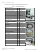
Section 2 – Cabinet Conversion Conversion Kit Contents and Replacement Parts List Table 1.
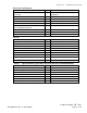
Section 2 – Cabinet Conversion CDs, Labels, and Manuals Description Qty Part Number Conversion Instructions & System Manual (This Document) 1 040-0050-01 Document, Software Restore 1 040-0060-01 Software, Game, Beach Head 2003: Desert War 1 050-0040-01 1 Software, Game, Beach Head 2000 1 050-0016-01 1 Software, Game, Beach Head 2002 1 050-0017-01 1 Software, V3 and gvrSX™ Recovery Disk XP Home, Multi Game Upgrade 1 050-0019-01 1 Software, Joystick Calibration Utility CD 1 050-0022-01
Section 2 – Cabinet Conversion Replace the Monitor (Optional) Note: Do Not use the Universal Video Controller (UVC) board with the Wells Gardner® monitor. If you have the Monitor Upgrade Kit, perform the steps in this section to remove the old monitor and install the 27-inch Wells-Gardner® monitor. Remove the Old Monitor 1. Open the service shelf, and remove the glass display shield and monitor bezel. 2. Disconnect ALL wiring from the back of the monitor.
Section 2 – Cabinet Conversion 4. Repeat the previous two steps to drill bolt holes in the other side of the cabinet. 5. Align the lower monitor bracket with the new bolt holes and bolt it in place using the nuts and bolts removed previously. 6. Install the four (4) supplied carriage bolts into the original bolt holes to give them a finished appearance. 040-0050-01 Rev. A 10/29/2004 © 2004 GLOBAL VR ® , INC.
Section 2 – Cabinet Conversion Install the New Monitor 1. Refer to the picture below and make sure that the monitor frame of the new 27-inch Wells-Gardner® Monitor has the holes required to mount it to the cabinet brackets. Both the top and bottom sections of the frame must have two pairs of holes (some monitor frames have only one pair of holes in each section). The inside pair of holes must be centered on the bracket, and measure 19-1/4" center-to-center. 2.
Section 2 – Cabinet Conversion 4. Use the old hardware to re-attach the monitor to the cabinet bracket (four places). 5. Install the new monitor bezel. 6. Clean and replace the glass display shield. 7. Replace the small retainer tab that secures the display shield in place. 8. Mount the monitor remote control board in a convenient location in the service tray. 9. Connect the monitor ground wire to a ground lug on the cabinet. 10.
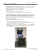
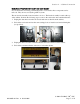
Section 2 – Cabinet Conversion 3. Install the exhaust fan behind the ventilation slot, just above the rear cabinet door, as shown by the arrow in the picture below. 4. Place the exhaust fan on the outside of the ventilation slots and use the mounting holes in the fan as a template to drill the mounting holes. Use an 11/64" drill bit to drill the four mounting holes for the exhaust fan. 5. Place the fan on the inside of the cabinet so that it will blow air out of the cabinet.
Section 2 – Cabinet Conversion Set Up the Hardware Set Up AC Power Distribution You must install the AC power strip/surge suppressor from the kit to provide power to the computer, new monitor (if installed), and ventilation fan. The actual wiring will vary depending on which cabinet you are converting. Use the instructions that follow as a general guideline for setting up AC power distribution. 1. Locate the AC power panel inside the cabinet.
Section 2 – Cabinet Conversion 6. Some older cabinets with CGA monitors have an AC isolation transformer that is used to power the monitor. These are often bulky, heavy transformers that take up most of the space on the bottom of the cabinet, and they cannot be removed unless you replace the monitor. If you connect a monitor that requires an AC isolation transformer directly into an AC power source, you will damage the PCB chassis on the monitor. 7.
Section 2 – Cabinet Conversion 3. Set jumper J8 on the Jamma conversion board to pins 1 and 2 for stereo, or pins 1 and 3 for mono audio, depending on how your cabinet audio is set up. 4. Place the boards next to each other in the service tray where you removed the old boards. Make sure that the Jamma connector on the Jamma wire harness can reach the Jamma Conversion Board before securing the boards to the cabinet. 5. Secure the boards with wood screws in the plastic feet.
Section 2 – Cabinet Conversion Install the Happ UGCI Board 1. Install four small plastic feet from the kit on the Happ UGCI board. 2. Mount the board below the control panel where the button and joystick harnesses will reach it, as shown in Figure 3. 3. Secure the board with wood screws in the plastic feet as shown in Figure 3. 4. Refer to the figure below, and Figure 5, Simplified Wiring Diagram, on page 43 to connect the Happ UGCI board. Figure 3. Happ UGCI Board Connections 5.
Section 2 – Cabinet Conversion Set Up the Computer The computer comes pre-loaded with the game software. There is no need to reload the software with the CDs in the kit. The Software recovery CDs are included in case you have a software problem in the future or wish to change the specific game titles available. CAUTION: The computer can be damaged very easily. Use caution when installing the computer. Avoid touching internal components.
Section 2 – Cabinet Conversion Connect the Computer Refer to Figure 7, Computer Rear Panel Diagram, on page 45, and Figure 5, Simplified Wiring Diagram, on page 44 to make the connections to the computer. 1. Connect the USB hub to one of the computer USB ports and install the game dongles in the USB hub. Refer to the section titled USB Game Dongles on page 37 for more information on the dongles and USB hub. 2.
Section 2 – Cabinet Conversion Secure the Computer Caution: Use caution to avoid damaging the computer. Always power OFF the cabinet before moving the computer. Once you have verified that everything is working properly, secure the computer to the cabinet. You will need a 6-inch clearance in the front of the computer to allow the CD-ROM drive tray to fully OPEN. Secure the computer to the bottom of the cabinet using four (4) #10 x ½" Phillips wood screws. 040-0050-01 Rev.
Section 2 – Cabinet Conversion Upgrade the Control Panel Perform the steps in this section to upgrade the old control panel with new buttons, joystick, and graphics. Prepare the Control Panel 1. Disconnect the wires from the buttons and other controls. 2. Remove the nuts and bolts that hold the plastic cover to the control panel surface. 3. Remove the buttons, trackball (or other controls), the clear plastic cover, and artwork from the control panel. 4.
Section 2 – Cabinet Conversion 4. Place the joystick direction sticker over the joystick hole. Make sure that it is properly aligned with the cabinet and monitor and then peel off the backing and apply the sticker. If the sticker has protective paper over the face, wet the paper and wait about 15 minutes before removing it to avoid damaging the artwork. 5. Center the button function stickers about 3/4-inch below the button holes as shown in the picture that follows.
Section 2 – Cabinet Conversion Apply the Cabinet Graphics and Marquee Artwork GLOBAL VR® requires that all converted cabinets adhere to the strict guidelines for finished cabinet artwork as described in this instruction manual. Perform the following steps to apply the side panel graphics and replace the old marquee artwork. 1. Place a gvrSX™ Logo sticker on each side of the cabinet, centered, level to the ground, at about eye level, as shown in the picture below.
Section 2 – Cabinet Conversion 6. If your cabinet has existing tournament rules artwork located between the speakers and just above the monitor, remove the screws around the metal plate that holds both the artwork and the speakers to the cabinet, as shown by the arrows in the picture below. 7. Remove the metal plate and replace the old artwork with the new gvrSX™ game graphics.
Section 3 – Power ON and Test the Cabinet Section 3 – Power ON and Test the Cabinet Before powering the cabinet ON for the first time, please verify the following: • • • AC power is correctly setup inside the cabinet. The DC power supply is correctly setup to provide power to the Jamma Conversion Board. All connections are correct and secure.
Section 3 – Power ON and Test the Cabinet Adjust the Universal Video Converter (UVC) The Universal Video Converter (UVC) is designed to work with most EGA and CGA arcade monitors. When you power the cabinet up for the first time, you may need to adjust the settings on the UVC board to match the monitor. To correctly set up the UVC, you must know the resolution and Horizontal and Vertical Sync setup of the monitor.
Section 4 – Using the Game Operator Menu Section 4 – Using the Game Operator Menu All gvrSX™ game audits, game adjustments, and control diagnostics are options of the Game Operator Menu. Press the Operator Button behind the coin mech door in the cabinet to activate the Game Operator Menu. The screen shown below is the first screen that you will see after pressing the Operator button.
Section 4 – Using the Game Operator Menu Machine Menu The Machine menu is the default screen displayed when you press the Operator Button. It displays the information described in the table below: Serial # Reserved for future use of Multi-Player or Tournament-Enabled Games. Machine Type Reserved for future use of Multi-Player or Tournament-Enabled Games. Hardware Version Reserved for future use of Multi-Player or Tournament-Enabled Games.
Section 4 – Using the Game Operator Menu Game Mode Menu The Game Mode menu is used to set up the type of money used at your location, the number of coins that are needed to start a game, and game play timeout, as described in the table below: Credit Display Defines whether Money or Arcade Credits are used to play this cabinet. The options to choose from are: Money, or Credits. International Settings Defines the type of money that will be used in this cabinet. The options available are: U.S.A., or U.K.
Section 4 – Using the Game Operator Menu Game Resets Menu The Game Resets menu allows you to restore the cabinet to the default settings, and delete various coin and game stats, as described in the table below: Restore Factory Settings Sets the Game Mode optional settings to the Factory Settings listed below. U.S.A. Factory Settings U.K. Factory Settings Credit Display Money Credit Display Money International Setting U.S.A. International Setting U.K.
Section 4 – Using the Game Operator Menu Coin Audits The Coin Audit menu shows the total number of coins collected for each game, and the cabinet total, as well as the last date and time the stats were reset. The Lifetime Stats are never reset and show the total number of Games Played for each installed game, and the cabinet total.
Section 4 – Using the Game Operator Menu Game Selection The Game Selection window allows you to disable installed games so that they are not available to play in the multi-game selection window. Select a title and press the Trigger Button to put an “X” next to the game that you want disabled. When you exit the Operator Menu, the game will be unavailable for play in the Multi-Game Selection. The game is not deleted, and can be re-enabled at any time by removing the “X” in the Game Selection Menu.
Section 4 – Using the Game Operator Menu any direction, a red arrow will indicate the direction that the Joystick is moving. When you are finished testing the player controls, press the Operator Button to exit back to the main Operator Menu. Monitor Calibration Test The Monitor Calibration Test shows a series of screens that allow you to adjust the monitor using the monitor remote control panel. Use the joystick to scroll through each monitor test screen.
Section 5 – Starting a Game Section 5 – Starting a Game With the proper number of credits inserted, use the joystick to choose the game you want to play, and press the Fire Button to confirm. If only a single game is installed on your cabinet, you will not choose a game, but will go directly to the next screen. At the next screen, choose the difficulty of play: Easy, Medium, or Hard. Each degree in difficulty will add more enemy squadrons to the game and weaken your shield against the enemy.
Section 5 – Starting a Game Playing a Beach Head Game Beach Head 2002, and Beach Head 2003: Desert War, both use the screen layout described below. Beach Head 2000 uses a different layout for the Information Bars. The goal of the game is to defend your post and destroy as much of the enemy as possible. The Information Bars on the screen, described in the table below, provide useful information about the game. Ref.
Section 5 – Starting a Game USB Game Dongles The three Beach Head games supplied with the cabinet use one USB game dongle. The dongle must be inserted in the USB port or the game will not work. When the USB Dongle is installed and working properly, a red LED will illuminate inside the dongle. For a USB Game Dongle to be recognized correctly, it must be inserted into the USB port before the cabinet is powered ON.
Section 6 – System Software CDs Section 6 – System Software CDs If the software running on your gvrSX™ computer develops problems, you can restore the software using the disks provided with your kit. The Windows XP System Disk will load the Operating System. Each Game CD will load one game. Please be aware, when you use the System Disk, you will erase all history for the coin and game audits stored in the software. Operating System Restore CD 1. System restore takes about 10 minutes.
Section 7 – Troubleshooting Section 7 – Troubleshooting Table 4. Problem No Picture on Monitor Picture is Misaligned or Color is Poor Possible Cause Possible Solution Power Problem Verify the AC power connection to the monitor. You can verify the monitor has power by looking for a small glow in the Neck of the CRT. Verify the Universal Video Converter has power; the red LEDs should be illuminated.
Section 7 – Troubleshooting Problem Audio is Distorted or Muffled Faulty Sound Channel Possible Cause Possible Solution Blown Speakers Remove the speaker grill covers, and visually inspect each speaker. Run the Sound Test from the Operator Menu to verify each speaker is working. Faulty Wiring A weak or low muffled sound is a sign of reversed speaker wires. Check for reversed wires on each speaker.
Section 7 – Troubleshooting No Control Panel or Button Functions No Power to the UGCI Board The UGCI board gets power through the USB cable. Make sure this cable is firmly connected to the board and computer. Faulty Wiring Verify that no wires are frayed or improperly shorting to ground in the wire harness. Faulty Power Supply Verify that the External PC Power Supply is working. This provides 12-volt and 5-volt DC power to the hardware connected to the wiring harness. Table 7.
Section 7 – Troubleshooting Problem Marquee Lamp is Faulty or Intermittent Improper Number of Credits given when Coins or Bills are Inserted Game will not accept Coins or Bills Possible Cause Possible Solution Faulty Fluorescent Tube Check the fluorescent tube for darkened or cracked end. Replace the Fluorescent tube if it looks worn. Faulty Fluorescent Fixture Verify the fluorescent tube pins make a good connection with the lamp fixture. Check the ballast for proper operation.
Section 8 – Diagrams and Schematics Section 8 – Diagrams and Schematics Configuration with New Wells-Gardner Monitor Happ UGCI Board Computer To USB Hub for Game Dongles. (One dongle per game.
Section 8 – Diagrams and Schematics Jamma Conversion Board J2 (Audio In) R Audio 2 Happ UGCI Board Computer USB Port USB Port Speakers Out L Audio 5 J6 GND 1 USB Port Video Blue 3 NC 5 Video Sync 4 3 Video Blue 5 Video Sync 4 Video GND Video GND 6 6 Hsync/ Composite J1 (PWR) ORG GND 5 BRN YAX 9 BLU GND 6 BRN UVC J7 1 Video Red 2 Video Green VCC 1 Dongle To Power Strip AC In Video Green 2 Dongle To Monitor or UVC VGA Port on Video Card J4 (Video In) Video Red 1 Joystick Dongle
Section 8 – Diagrams and Schematics Computer Rear Panel Diagram Computer ON/OFF Switch Voltage Switch (115V or 230V) AC Power In Computer Power Supply Cooling Fan 115 PS/2 Keyboard Port (Purple) PS/2 Mouse Port (Not Used) Com Port (Not Used) Parallel Port (Not Used) Computer VGA Port Not Used USB Ports (4) - One Port to Happ UGCI Card - One Port to Game Dongle Ethernet Port (Not Used) Dongle Audio Ports (Green Blue Red) Video Port To Monitor or UVC Green to Audio In on Jamma Conversion Board Vid
Section 8 – Diagrams and Schematics Warranty Service If at some point you require warranty service, contact your distributor. If the technical support staff determines that your game is defective, a Return Merchandise Authorization (RMA) number will be issued.
Section 8 – Diagrams and Schematics 040-0050-01 Rev. A 10/29/2004 © 2004 GLOBAL VR ® , INC.
Technical Support GLOBAL VR® provides free telephone, e-mail and online support for systems during the warranty period. In addition to helping with troubleshooting and diagnosing defective parts, GLOBAL VR® technical support is prepared to help you with questions about the operation of your game. When you contact technical support, please provide the following background information to aid our technical support process: • Cabinet’s Game Serial Number (found on the back of the cabinet).