
Specifications
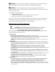
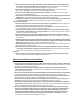
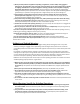

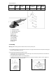


Figure 1 Figure2
3) Fittingthegrindingdisc:(Figure3andFigure4)
A. Placetheinnerflange(7)overthespindlemakingsurethefitistight
B. Place the grinding disc(8) on the top of the inner flange ensuring the bore fits into the step of the
flange
C. Mounttheconcave
recesssideoftheouterflange(9)overthespindle
D. Pressthespindlelockingbutton(2)firmandensurethereisnomovementinthespindle.While
thespindlelockisdepressed,tightentheouterflangeinaclockwisedirectionusingthespanner(10).(See
figure4)
Figure 3 Figure 4
Allowtheanglegrindertoruninidleforatleastaminutewiththegrinding,vibrationdiscshouldbe
immediatelyreplaced.
3.Operation
SwitchOn/offthetool
1)Whenstartingholdthe toolfirmlywithbothhandsi.e.One handonthemotorhousingandtheother
onthesideauxiliaryhandle(1).
2)Startthetoolbypressingtriggerinwards,thenthetoolisenergizedandstartstooperate.(Seefigure5)
3)Thetoolwillstopassoonasreleasingthetriggerofswitch.
Figure5