OPERATING INSTRUCTIONS MANUEL D'INSTRUCTIONS MANUAL DE INSTRUCCIONES MODEL ATD 37155 IMPORTANT OPERATING INSTRUCTIONS SAVE THESE INSTRUCTIONS 3.300.
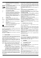
INSTRUCTION MANUAL FOR WIRE WELDING MACHINES IMPORTANT: READ THIS MANUAL CAREFULLY BEFORE INSTALLING, USING, OR SERVICING THE WELDING MACHINE, PAYING SPECIAL ATTENTION TO SAFETY RULES. CONTACT YOUR DISTRIBUTOR IF YOU DO NOT FULLY UNDERSTAND THESE INSTRUCTIONS. 1 INSTALLATION C) Earth cable D) Yellow LED Lights only when the thermostat is tripped and interrupts the machine operation. E) Green LED Indicates that the machine is turned on. F) Welding torch G) Handle Must not be used to lift the machine.
N° Serial number which must be stated when asking for information or servicing related to this machine. IEC 60974-1 The welding machine is manufactured according EN 50199 to these international standards. Single-phase Transformer - Rectifier MIG/MAG. Suitable for continuous wire welding I2 max Unconventional welding current. The value represents the maximum level that can be obtained in welding. Uo Secondary no-load voltage.
5.2 Fig. 3 When you have finished welding, turn off the machine and close the gas cylinder. For the correct welding angle see figure 5. 5.1.2 Without gas protection. Connect the cables as shown in the figure 4. WELDING ALUMINIUM The welding machine must be prepared as for welding mild steel with gas protection, but with the following differences: - 100% ARGON as the protection gas for welding. - A wire having a composition suited to the base material to be welded.
6.2.1 Instructions for performing repairs l After rewinding the transformer or inductance, the welding machine must pass the applied voltage tests as indicated in table 2 of paragraph 6.1.3 of the standard EN 60974.1 (CEI 26.13). Compliance must be verified as specified in 6.1.3. l If no rewinding has been done, a welding machine that has been cleaned and/or revised must pass an applied voltage test with test voltage values equal to 50% of the values given in table 2 of paragraph 6.1.3.
graphite, cadmium, zink, chrome, mercury or beryllium, unless you have the proper breathing set. l The electric arc creates ozone. A long exposure to high concentrations may cause headaches, nasal, throat and eye irritation as well as serious congestions and chest pains. IMPORTANT: DO NOT USE OXYGEN FOR VENTILATION. l Gas leaks in a confined space should be avoided. Leaked gas in large quantities can change oxygen concentration dangerously. Do not bring gas cylinders into a confined space.
RE WOUNDS. l Do not press gun trigger until instructed to do so. l Do not point gun toward any part of the body, other people, or any metal when threading welding wire. 7.9. MOVING PARTS CAN CAUSE INJURY. Moving parts, such as fans, can cut fingers and hands and catch loose clothing. l Keep all doors, panels, covers, and guards closed and securely in place. l Have only qualified people remove guards or covers for maintenance and troubleshooting as necessary.
MANUEL D’INSTRUCTIONS POUR POSTES A SOUDER A FIL IMPORTANT: AVANT D’INSTALLER, EMPLOYER, OU BIEN COMMENCER TOUT ENTRETIEN AU POSTE A SOUDER, IL FAUT LIRE LE CONTENU DE CE MANUEL EN FAISANT PARTICULIERE ATTENTION AUX NORMES DE SECURITE. CONTACTEZ VOTRE DISTRIBUTEUR SI VOUS N’AVEZ PAS COMPLETEMENT COMPRIS CES INSTRUCTIONS. 1. INTRODUCTION Cette machine ne doit être employée que pour des opérations de soudure et ne doit pas être utilisée pour décongeler les tuyaux.
I2 max Uo X I2 U2 U1 I1 max. I1 eff. IP21 S Courant de soudure non conventionnel. Le valeur représent la limite maximale pouvant être obtenue en soudure. Tension à vide secondaire. Le facteur de marche exprime le pourcentage de 10 minutes au cours desquelles le poste à souder peut travailler avec un courant fixé sans provoquer des surchauffages. Par exemple: X = 60% a I2 = 100 A. Cela signifie que le poste à souder peut souder avec un courant I2 = 100A pendant 6 minutes sur 10, c’est-à-dire 60%.
4.2 NOTES GENERALES Avant d’utiliser ce poste à souder, lire soigneusement les normes CEI 26/9 ou bien CENELEC HD 407 et CEI 26/11 ou bien CENELEC HD 433. En outre vérifier l’intégrité de l’isolement des câbles, de la torche et du câble masse. 5 5.1 SOUDURE SOUDURE DE L’ACIER DOUX. avec la norme AWS AS.20 E71 TII ou bien E71 TGS, apte à l’emploi sans protection de gaz. Raccorder la pince du câble de masse à la pièce à souder.
6.1 NOTES GENERALES l Arrêter le poste à souder et retirer la fiche d’alimentation de la prise avant d’effectuer toute opération de contrôle et entretien. l Les parties en mouvement peuvent causer des lésions graves. l Se tenir éloigné des parties en mouvement. LES SURFACES INCANDESCENTES peuvent causer des brûlures graves. l Laisser refroidir avant de procéder a l’entretien.
bles ou inflammables. l Ne pas effectuer de soudure sur des pièces qui possèdent des insterstices pouvant contenir des matériaux inflammables. l Ne pas travailler dans un milieu contenant des concentrations élevées de vapeurs combustibles, des gaz ou des poussières inflammables. l Contrôler toujours la zone de travail une demi-heure après la soudure pour s’assurer qu’il n’y ait pas un début d’incendie. l Ne pas garder dans les poches des matériaux combustibles comme des briquets ou des allumettes. 7.
Maintenir les régulateurs de pression en parfait état. Des régulateurs endommagés peuvent provoquer des inconvénients ou causer des accidents. Ils doivent être réparés uniquement par un personnel qualifié. l Ne pas utiliser des régulateurs pour des gaz différents de ceux pour lesquels ils ont été fabriqués. l Ne jamais utiliser un régulateur qui perd ou qui apparaît physiquement endommagé. l Ne jamais lubrifier un régulateur avec de l’huile ou de la graisse. l C) TUBES.
MANUAL DE INSTRUCCIONES PARA SOLDADORAS DE HILO IMPORTANTE: ANTES DE LA INSTALACION, DEL USO O DE CUALQUIER MANTENIMIENTO A LA SOLDADORA, LEER EL CONTENIDO DE ESTE MANUAL PONIENDO PARTICULAR ATENCION A LAS NORMAS DE SEGURIDAD, CONTACTEN AL DISTRIBUIDOR SI NO HAN ENTENDIDO POR COMPLETO ESTAS INSTRUCCIONES. 1 PRELIMINARES D) Led de color amarillo. Se enciende sólo cuando el termostato interrumpe el funcionamiento de la soldadora. E) Led de color verde. Señala el encendido de la máquina.
IEC 60974-1 La soldadora se ha construido según estas EN 50199 normas internacionales Transformador - Rectificador Monofàsico MIG/MAG. Adapto para soldadura de hilo continuo. I2 max. Ccorriente de soldadura no convencional. El valor representa el límite máximo que se puede obtener en soldadura.
- Para soldar ANTICORODAL hilo 3 + 5% silicio. - Para soldadura PERALUMAN hilo 5% magnesio. - Para soldadura ERGAL hilo 5% magnesio. Utilizar muelas y cepillos metálicos especificas para el aluminio sin usarlos jamás con otros materiales. RECUERDEN que la limpieza es calidad Las bobinas de hilo deben ser conservadas dentro de bolsas de nilón con un deshumidificador. Para la adecuada inclinación de soldadura ver la figura 5. Fig. 3 Acercarse al punto de soldadura y presionar el pulsador de la antorcha 39.
6.2 REPARACIONES DE LAS SOLDADORAS La experiencia ha demostrado que muchos accidentes mortales tienen origen en reparaciones no efectuadas según normas. Por este motivo, un atento y completo control en una soldadora reparada es tan importante como el efectuado en una soldadora nueva. Además de esta forma los productores podrán ser protegidos contra el ser considerados responsables de defectos, cuando la culpa sea de otros. 6.2.
chas, hay que cambiarlo. l Evitar el uso de ropa pegajosa y grasienta.Una chispa podría incendiarla. l Las partes metálicas incandescentes como por ejemplo pedazos de electrodos y pedazos sobre los cuales se trabaja, hay que cogerlos siempre con guantes.
que cortar usando guantes y prendas de vestir aislantes. Mantener las prendas de vestir (guantes, zapatos, gorros, vestidos) y el cuerpo secos. l No trabajar en ambientes húmedos o mojados. l No apoyarse a la pieza que hay que soldar. l Si hay que trabajar cerca o en una zona peligrosa hay que usar todas las precauciones posibles. l Si se siente cualquier golpe de descarga eléctrica, aunque sea pequeño, hay que interrumpir inmediatamente las operaciones de soldadura.
Pos 1 2 3 4 5 6 7 8 9 10 11 12 13 14 15 16 17 20 21 22 23 24 25 26 27 29 32 33 34 35 37 40 41 42 43 44 45 46 47 48 49 50 Description Designation Denominacion KNOB KNOB FRAME CLOSING HANDLE PANEL SIDE DRIVE ROLL WIRE FEED MOTOR CONTROL PANEL RING SPRING COIL SUPPORT SPACER COIL SUPPORT HINGE RUBBER MAT COVER CENTER DEVIDER HOSE BARB JOINT GAS HOSE SOLENOID VALVE MAIN INPUT CABLE CABLE HOLDER BACK PANEL FIXED SIDE PANEL CABLE HOLDER FAN TRANSFORMER THERMOSTAT THERMOSTAT SUPPORT UNDERCARRIAGE EARTH CABLE