
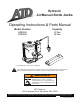
User's Manual

2
SAFETY AND GENERAL INFORMATION
Save these instructions. For your safety, read, understand, and follow the information provided with and on this
device before using. The owner and/or operator shall have an understanding of the device, its operating characteristics
and safety operating instructions before operating the equipment. The owner and/or operator shall be aware that use
and repair of this product may require special skills and knowledge. Instructions and safety information shall be read
to and discussed with the operator in the operator's native language, making sure that the operator comprehends
their contents, before use of this equipment is authorized. If any doubt exists as to the safe and proper use of this
device, remove from service immediately.
Inspect before each use. Do not use if abnormal conditions such as cracked welds, damaged, loose or missing
parts are noted. Any equipment that appears damaged in any way, is found to be worn, or operates abnormally shall
be removed from service until repaired. If the equipment has been or is suspected to have been subjected to an
abnormal load or shock, immediately discontinue use until inspected by a factory authorized repair facility (contact
distributor or manufacturer for list of authorized repair facilities). It is recommended that an annual inspection be
made by an authorized repair facility. Labels and Operator's Manuals are available from the manufacturer.
PRODUCT DESCRIPTION
ATD Tools Air Hydraulic Bottle Jacks are designed to lift rated capacity loads consisting of one end of a vehicle.
Immediately after lifting, the load must be supported by a pair of appropriately rated jack stands. Ensure that air
source can dedicate 7.8 CFM @ 110-175 psi to each jack operated. A minimum of 150 psi air pressure is required
to raise rated capacity load.
WARNING: Never use a hydraulic jack as a stand alone support device. After lifting, immediately support the
vehicle with appropriately rated jack stands. Never place any portion of your body under the vehicle when lifting
or lowering.
PREPARATION
Before Use
1. Before using this product, read the operator's manual completely and familiarize yourself thoroughly with the
product, its components and recognize the hazards associated with its use.
2. Verify that the product and application are compatible, if in doubt call Technical Service (816) 891-6390.
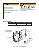
3. Assemble handle, ensure spring clips align with slots.
4. To familiarize yourself with basic operation, use the notched end of provided handle to engage and turn the release
valve:
a. Clockwise until rm resistance is felt to further turning. This is the ‘CLOSED’ release valve position used to
raise the ram plunger.
b. Counter-clockwise, but no more than 1 turn from the closed position. This is the ‘OPEN’ release valve position
used to lower the ram plunger.
5. With saddle fully lowered, and release valve closed, pump the operating handle. If ram responds immediately,
jack is ready for use. If jack does not respond, follow Bleeding/Venting Trapped Air procedure below.
6. Pour a teaspoon of good quality, air tool lubricant into the air supply inlet of the lift control valve. Connect to air
supply and squeeze lift control valve for 3 seconds to evenly distribute lubricant.
NOTICE: This product is equipped with the popular 1/4" NPT air coupler. When installing a different air coupler
of your choice, ensure that thread tape or compound is used when servicing connections. To ensure dependable,
trouble free operation an in-line air dryer and oiler is recommended.
7. Check that the pump operates smoothly and that the extension screw adjusts up/down easily before putting into
service. Replace worn or damaged parts and assemblies with genuine ATD Tools replacement parts only.
Bleeding/Venting Trapped Air
With the release valve in the OPEN position (4b above) and with ram plunger fully lowered, locate and remove the
air vent screw/ller plug. Insert the handle into the handle sleeve, then pump 6 to 8 full strokes. This will help release
any pressurized air which may be trapped within the reservoir. Oil level should be even with the bottom of the oil
ller hole. Reinstall the air vent screw/ller plug.
!