
user manual

15
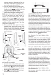
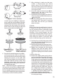
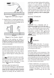
ure 8A. If you are installing an eight-inch
spool, install the spindle adapter and drive
brake hardware as shown in Figure 8B. The
purpose of the drive brake is to cause the
spool of wire to stop turning at nearly the
same moment that wire feeding stops.
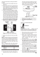
6. Once the drive brake hardware is installed,
set the spool tension. With one hand, turn
the wire spool and continue turning it while
adjusting the tension on the spool. With
your free hand, tighten (turn clockwise) the
knob that holds the spool in place. Stop
tightening when drag is felt on the wire
spool that you are turning, then stop hand-
turning the wire spool.
Note: If TOO MUCH tension is applied to the
wire spool, the wire will slip on the drive roller
or will not be able to feed at all. If TOO LITTLE
tension is applied, the spool of wire will want to
unspool itself. Readjust the drive brake ten
sion
as necessary to correct for either problem.
7. After checking to make sure that your
welder is disconnected from the AC
power source,
free the leading end of
the wire from the spool, but do not let go
of it until instructed to do so, or the wire
will unspool itself.
8. Use a wire cutter, cut the bent end
the
leading end of the wire so that only a
straight leading end remains.
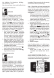
9. Flip down the screw holding the drive ten-
sion arm in place and lift the tension arm up
the drive roller.
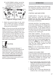
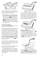
10. Insert the leading end of the wire into the
inlet guide tube. Then push it across the
drive roller and into the gun assembly
about six inches.
CAUTION
Make certain that the welding wire is actual-
ly going into the gun liner. Be very sure it
has not somehow been accidentally routed
alongside the liner or even in some other
direction. If this should happen, the wire
could feed inside the cable casing or take a
right angle and follow the wires and gas
hose inside
the welder. It could also feed
back on itself jamming up the mechanism.
11. Line the wire up in the inside groove of the
drive roller, then allow the drive tension arm
to drop onto the drive roller
.
12. Flip the quick release drive tensioner back
up into position on the drive tensioner arm.
13. Tighten (turn clockwise) the drive tension
adjusting screw until the tension roller is
applying enough force on the wire to pre-
vent it from slipping out of the drive assem-
bly.
14. Let go of the wire.
15. Connect the welder power cord to the ac
power source. Turn the welder ON by set-
ting the VOLTAGE switch to the voltage
(heat) setting recommended for the gauge
metal that is to be welded. Refer to the label
mounted on the cover, inside the drive com-
partment, for recommended voltage (heat)
settings for your welding job. The VOLTAGE
selector controls the weld heat. There are
four voltage heat selections (numbered 1
through 4) available on this welder. Position
1
provides the lowest voltage (heat) and
position 4 the highest voltage (heat).
16. Set the WIRE SPEED control to the middle of
the wire speed range.
Figure 7. Wire Installation
Figure 8A. Drive
Brake Hardware
Installation
Figure 8B. Spindle
Adapter and Drive
Brake Installation