
Specifications


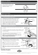

Attaching the Displays
D
75mm x 75mm (3” x 3”) mounting hole pattern
Display
4x10mm
Screws
75mm
(3”)
75mm (3”)
100mm x 100mm (4” x 4”) mounting hole pattern
NOTE:
Ensure that the
flat side of each
Extension Clip sits
against the back
of the display
Extension Clips
4x12mm or
4x16mm Screws
100mm
(4”)
100mm (4”)
Display
Installing Cable Management
E
E.1. Push the four supplied Cable Clips into the holes on the underside of the Swing Arm Double as shown.
E.2. Feed the cables into the Cable Wrap Applicator.
E.3. Insert the Cable Wrap Applicator into the Cable Wrap as shown.
E.4. Squeeze the nose of the Applicator and place inside the Cable Wrap ensuring that the opening edges of the Cable
Wrap face towards the nose of the applicator as shown in diagram.
E.1.
Push in
Clips
Nose
E.2. E.3.
E.4.
C.2.1. Drill Mounting Hole
Drill a 13mm (½”) hole in your work surface at the desired location for your arm.
C.2.2. Install as shown
Insert the M8 Interscrew up through the hole in the work surface.
Using both hands, secure the M8 Interscrew with the 5mm
Allen Key supplied in the Desk Clamp Box and use the other
hand to tighten the Threaded Rod into the Interscrew with the
supplied Top Cap Tool. (see diagram C.2.3.)
5mm Allen Key
Top Cap Tool
Threaded Rod
Washer
Base Casting
M8 Interscrew
13mm (
1
/
2
”) Hole
Desk Top
Tighten
Firmly
C.2.3.
C.2. Bolt Through
Attaching the Cable Wrap to the Arm
F
F.1. Position the displays at their highest
possible position to ensure that there is
sufficient cabling at the end of the arm
so the cables are not stretched or pulled
out when the displays are moved.
BEFORE PROCEEDING TO THE NEXT STEP PLEASE NOTE:
Swing Arm Double will only work when a display is properly installed.
DO NOT adjust tension screws or gas strut until your display has been attached.
Cable Clips (x4)
Cable Tube
Manager Clip
Cable Wrap
Mounting Options Continued
C