ATEAGO S1 Cleaning Robot User Manual Version: 1.5.4s Note: This document provides machine-related deployment procedures and precautions. Follow the instructions in the document to avoid other abnormal situations when using the machine in the future.
Introduction to Robots Use environment requirements Please use this product in accordance with the instructions of the manual. Any loss caused by improper use shall be borne by the user.
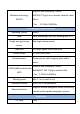
Hardware parameters Hardware parameters Index performance Product specification Product Size Length 684mm * Width 500mm * Height 600mm product weight Product color product material Environmental requirements 80kg with packaging white 3D printed parts Storage temperature: -15°C~55°C; Working temperature: 0°C ~ +50°C Humidity (RH): 10%~90% Android specifications operating system Android 5.
Support dual frequency 2.4&5G Wireless technology AP6255 WIFI 802.11b/g/n non-domain network cable office 11ac 5.15GHz-5.825GHz ROS Navigation specifications operating system Lidar Single axis gyroscope LINUX Laser wavelength 905 nm, working area 270° Yaw angle measurement sensor hard disk motor driven Infrared sensor 32G high-speed solid state drive 6.
Water tank Volume 15L Power system 24V Rectifier LPS-425-40A24U DC24V output power 48W rectifier Motor Vacuum cleaner, solenoid water valve switch, suction pump motor, roller motor charging method adapter Robot input power battery Automatic recharge, DC direct charge enter:AC110-240V.50-60HZ Output:DC43.2V-5A 42V--5A 25AH lithium iron phosphate, 38.4V/960W Overcurrent protection, intelligent power off, Charging pile parameters output rated voltage: 43.
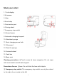
Meet your robot 1. 7 inch display 2.3d camera 3. Lidar 4. Brush strip 5. Dust suction port 6. Driving wheel 7. Emergency stop switch 8. Infrared sensor 9. Automatic charging shrapnel 10. Absorbent sponge 11.Direct charging source hole 12. Ultrasound 13.Clean the sponge 14. Universal wheel 15. Trash box 16.Water tank Cleaning precautions: ① Touch screen ③ Laser navigation.
Use your robot 1. Boot The power button is located on the base 11 on the back of the robot. It is a button switch. Press it once to turn it on, and press and hold the power button for 3 seconds to turn it off.
2. Charging Get to know your charger The adapter plug needs to be plugged into the 110-220 V voltage, and the DC head is plugged into the automatic charging pile. At this time, the green light of the charging pile will be on, indicating that it is ready to charge.
Direct charging: plug the power adapter cable into the power supply on the back of the robot Automatic charging hardware description Placement of charging pile 8
Notes on the selection of charging pile location 3. Navigation Note:The following content is an introduction to all the functions of the robot deployment background. The functions that must be operated are as shown in the points 1, 2, 3, 4 and 5 in the following figure. Other functions depend on the specific scenarios and usage conditions.
The step 1 [Network Settings] Note: The router network segment cannot be the 192.168.10.x network segment 1. Open the [Settings]-[WLAN] on the Android screen of the robot to connect to Wi-Fi 2. Open the Ftp application and enter the following interface. Follow the steps shown in the figure. If the Wi-Fi password already exists, click "Send Wi-Fi Information to Connect to ROS".
① Check the Wi-Fi name you want to connect to ② Enter Wi-Fi password ③ Send Wi-Fi information to the navigation system ( just click once, don't click repeatedly) ④ Show IP for connection success (show 127.0.0.1 for connection failure) 3. The scanning device should be connected to the same LAN as the machine. Open the browser and input the IP address of the machine (Chrome browser is recommended) If the Wi-Fi connection fails, you can click ③ again to reconnect.
The step 2 [ Build mode ] The purpose of building the map is to let the robot know the working environment The robot needs to scan the actual environment and construct an "original map". During the navigation process, the robot can compare with the original map based on the real-time scanning situation and find its own position.
1,After entering the webpage, the default state is "Navigation Mode", click to switch to "Mapping Mode" and select "Laser Mapping" to enter the state as shown below to start scanning.
①Get IP from FTP software ②Switch to mapping mode and select "Laser Mapping" 2,After entering the "map mode", the machine first rotates in place to clean the surrounding feature points, and the speed should not be too fast when rotating, and the machine can be controlled to go after one rotation. In narrow areas, you can walk straight. Pay attention to the gaps during walking.
Figure 1: mismatch between laser and terrain (when the laser does not match the terrain, stop and wait for the laser to match the terrain before pushing the robot to build the map) Figure 2: matching of laser and terrain (some areas need robot to turn to be able to scan clearly, such as wide terrain and room) 4,Do not move the machine after the machine reaches the end point. Just observe whether the map is clean, without ghosting and matches the actual terrain.
matters needing attention: 1. When pushing or controlling the robot, walk slowly and observe whether the laser matches the terrain. If there is a mismatch, stop and wait for the laser to match the current terrain. 2. After the robot reaches the destination, observe whether the map is clean without ghosting and matches the actual terrain. If there is no obvious dislocation, click "composition complete". If there is any dislocation, please wait for a period of time, and the algorithm will correct it.
Step 3 [ Edit clean area ] Edit: Use polygons to draw the area that needs to be cleaned Ranging: measuring distance Clean area: Click to pop up all clean areas for editing The step 4 [ Virtual wall ] Edit the function of virtual wall: restrict the active area of robot 17
Drag: This mode can zoom, pan and rotate the map.
figure 1 Actual environment figure 2 Map scanned by laser figure 3 error figure 4 correct Example: table Note: the laser can only scan one horizontal plane, so when drawing the virtual wall, consider the desktop projection figure 1 Actual environment figure 3 error figure 2 Map scanned by laser figure 4 correct matters needing attention: 1. The minimum passing distance of the machine is 1.
2. The main function of the virtual wall is to draw the robot's moving space and separate the areas where the robot does not want to travel with the virtual wall. 3. Some areas that do not need to be driven or cannot be scanned by laser (glass walls, tables and chairs, steps, transparent and fragile objects, etc.) please make sure to build virtual walls.
is not significant. If the map is too different from the actual environment, it is recommended to scan the map again. ① Click Save to apply the map modification ② Clear drawn polygons ③ Here is the drop-down menu. You can select different amount map area types Blank area: remove the noise (such as the noise left by pedestrians walking on the map and temporary obstacles, etc.) during the process of scanning the map. Do not remove the real obstacles as noise.
when building the map, so it is necessary to draw obstacles artificially on the map (note that the obstacles drawn must match the obstacles that can be swept by the real laser). Unknown area: some frequently changing feature points need to be drawn into unknown areas (for example, the area where robots will not walk outside the glass wall).
①You can drag on the map to get the coordinates of the specified location for calibration ②You can also get the current position of the robot for calibration ③Click on the right side to pop up the toolbar 23
The Step 8 [ Map ] ①Edit map name ④Delete this map ② Apply this map ③ Export the map to the computer ⑤ Mouse over to show preview map, click to show original image Note: The map will not be applied immediately after uploading, you need to find the row of the map in "All Maps" and click the "Apply" icon 24
The Step 9 [ Upgrade ] ① Apply this version ② Delete this version The Step 10 [ Debug ] Navigation speed: adjust the travel speed of the machine (unit: m/s) 25
Perform cleaning tasks Note: Before using this function, you need to deploy the map according to the previous steps Open the "Clean Robot" APP on the Android screen and you will enter the following interface.
1. System Settings Starting up: Whether to start the application automatically when booting up Minimumautocarge: when the power is lower than the set value, trigger the machine to automatically recharge Task power: When the machine triggers "automatic charging" during the execution of a task, the machine will return to charging.
2.
3. Hand clean Start cleaning: Click "Start cleaning" to pop up a cleaning area selection box, select the area to be cleaned and click OK to start cleaning Return to charging: Click on‘Return to Charge’and the machine will immediately return to the charging station for charging 4.
Opening method: standing in front of the machine on the right hand side as shown in the figure below, there is a handle to pull the upper cover of the machine and it will open automatically. How to take out the water tank and dust box Note: The vacuum box and water tank should be cleaned regularly. When the machine reaches the set mileage, the status will be reported. At this time, the vacuum box and water tank need to be cleaned.
As shown in Figure 2 above, the‘water tank’and the‘dust suction box’can be taken out and cleaned Water tank: Twist the lid with the straw to lift the water tank Vacuum box: Open the buckle on the lid, then take out the cloth bag in the vacuum box and clean it.
As shown in the figure above, first open the cover of the mopping module, then pull the buckle, and pull out the mopping module box, then take out the sponge inside the box and clean it, and then move the mopping module box. Clean it with a brush, finally wring the sponge dry and put it back.