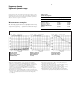
Agilent 8703A Lightwave Component Analyzer Technical Specifications 1300 nm or 1550 nm carrier 130 MHz to 20 GHz modulation bandwidth Single wavelength configuration
Introduction A powerful combination of calibrated 20 GHz lightwave and microwave measurement capabilities is described in this Agilent 8703A technical specifications.
Agilent 8703A Performance overview Table 2. Agilent 8703A performance overview2 System dynamic range..(see pages 5, 11, 14) Transmission test (typical) Optical-to-optical: 38 to 51 dBo Optical-to-electrical: 105 to 110 dBe Electrical-to-optical: 75 to 95 dBe Electrical-to-electrical: 100 to 110 dBe Microwave source.................... Reflection test (typical) Optical: 31 to 44 dBo Electrical: 36 to 56 dBe Distance-time domain........... (see page 13) Length/location (typical) Range: 10 ns to 0.
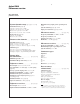
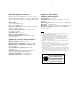
Agilent 8703A Block diagram Figure 1. Simplified block diagrams for lightwave and microwave test sets and information processor INFORMATION PROCESSOR MICROWAVE TEST SET S S ALC S Samplers Sampler Drive Phase Lock MOD Bias Tee 0.13–20 GHz RF Source Step Attenuator Bias Tee RF Port 1 LIGHTWAVE TEST SET RF Port 2 External Detector DAC MOD Laser 1300 or 1550 nm ALC Isolator Polarization Controller (Peak) Optical Switch (Opt.
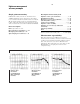
Frequency domain lightwave dynamic range Specifications describe the instrument’s warranted performance for the temperature range of 23 ±3°C after a three hour warm-up. Supplemental characteristics describe useful, non-warranted performance parameters. These are denoted as “typical” or “nominal”. Measurement examples The following graphs show device (DUT) measurements 9 compared to typical (– – –) 8703A measurement ranges .
Lightwave source and receiver characteristics Table 4. Lightwave source characteristics9 Description Opt 210 (DFB laser)10 Opt 220 (DFB laser)10 Opt 100 with Agilent 83424A Opt 100 with Agilent 83425A Wavelength 1550 ±10 nm 1308 ±10 nm 1550 ±10 nm 1308 ±10 nm Spectral width (typical) <50 MHz <50 MHz <50 MHz <50 MHz Average optical output power11 Maximum: Typical: Minimum: 600 µW (–2.2 dBm) 260 µW (–5.9 dBm) 125 µW (–9.0 dBm) 600 µW (–2.2 dBm) 260 µW (–5.9 dBm) 125 µW (–9.
External lightwave sources22 Option 100 allows external lightwave sources to be used with the Agilent 8703A lightwave component analyzer. The external sources must conform to the following characteristics.
Lightwave measurement accuracy summary Lightwave measurement uncertainty is presented in the following graphs and tables. This covers three types of measurements: optical (transmission and reflection) measurements, optical-to-electrical measurements, and electrical-to-optical measurements. Data is recorded after an 8703A accuracy enhancement has been performed using the indicated calibration type.
Optical-to-electrical30 Electrical-to-optical30 Measurement setup Measurement setup Calibration type: response & match Calibration standards: Lightwave receiver factory calibration data Agilent 85052D RF calibration kit Connectors and cables: HMS-10 lightwave connectors 40 cm single mode fiber 3.
Lightwave measurement accuracy examples Single point uncertainty Description of uncertainty term Individual uncertainty elements are shown below for a 10 GHz modulation frequency data point of a photodiode receiver transfer function measurement done on an 8703A. The uncertainty graphs on pages 8 and 9 summarize the results of this same analysis for optical and electro-optical device measurements across wide modulation bandwidths. Lightwave source port return loss . . . . . . . . . . . . . . . .
Frequency domain microwave performance summary Specifications describe the instrument’s warranted performance for the temperature range of 23 ±3°C after a three hour warm-up. Supplemental characteristics describe useful, non-warranted performance parameters. These are denoted as “typical” or “nominal”. Table 6. System dynamic range31 Bias port Frequency range (GHz) 0.13 to 0.5 0.
Microwave measurement accuracy summary Microwave measurement accuracy for the 8703A analyzer is presented in the following graphs and tables. All data is taken after an 8703A accuracy enhancement using the calibration type shown. This analysis accounts for the following errors33: • Residual systematic errors (Table 7) • System dynamic accuracy (dB from reference)34 • 3.
Distance-time domain performance summary Introduction Lowpass step response42: Analog and digital device design, testing and trouble shooting are made easier by using both the distance-time domain and frequency domain capabilities of the 8703A. This combination lets the user: 1) Discover if a problem exists. 2) Locate and quantify potential causes of the problem (i.e. unexpected reflections, attenuations, etc.
Distance-time domain performance summary cont'd Frequency bandwidth (GHz) Measurement description 0.13 to 12.0 0.
General information Group delay measurements Microwave measurement calibration types Group delay is computed by measuring the phase change within a specified frequency aperture (determined by the frequency span and the number of points per sweep). The phase change, in degrees, is then divided by the frequency aperture, in Hz (times –360). Frequency response: Simultaneously corrects for magnitude and phase frequency response errors for either reflection or transmission measurements.
Environmental characteristics Operating temperature 0 to 55°C Warranted temperature 23 ±3°C Non-operating storage temperature –40° to +70°C 8703A Lightwave Component Analyzer Power: 47.5 to 66 Hz: 90 to 132 volts, 198 to 264 volts, 350 VA (for top plug) +95 VA (for bottom plug) = 445 VA total maximum Weight: Net, 50 kg (110 lb.); shipping, 57 kg (125 lb.) Dimensions: 370 H x 425 W x 502 mm D (14.57 H x 16.73 W x 19.76 in. D) Allow 50 mm (2.0 in.) additional depth for front panel connectors.