Agilent 2-Port and 4-Port PNA-X Network Analyzer N5249A - 10 MHz to 8.5 GHz N5241A - 10 MHz to 13.5 GHz N5242A - 10 MHz to 26.
Documentation Warranty THE MATERIAL CONTAINED IN THIS DOCUMENT IS PROVIDED "AS IS," AND IS SUBJECT TO BEING CHANGED, WITHOUT NOTICE, IN FUTURE EDITIONS. FURTHER, TO THE MAXIMUM EXTENT PERMITTED BY APPLICABLE LAW, AGILENT DISCLAIMS ALL WARRANTIES, EITHER EXPRESS OR IMPLIED WITH REGARD TO THIS MANUAL AND ANY INFORMATION CONTAINED HEREIN, INCLUDING BUT NOT LIMITED TO THE IMPLIED WARRANTIES OF MERCHANTABILITY AND FITNESS FOR A PARTICULAR PURPOSE.
Documentation Warranty ............................................................................................................................................. 2 DFARS/Restricted Rights Notice ................................................................................................................................ 2 Definitions .......................................................................................................................................................................
Table 12b. Power Sweep Range (dB), Options 219 or 419 ................................................ 27 Table 12c. Power Sweep Range (dB), Options 219 or 419 with 0291 ............................... 28 Table 12d. Power Sweep Range (dB), Options 224 or 423 ................................................ 28 Table 12e. Power Sweep Range (dB), Option 224 ............................................................... 29 Table 12f. Power Sweep Range (dB), Options 224 or 423 with 0291 ........................
Table 37. Cycle Time vs. IF Bandwidth - Typical ................................................................ 48 Table 38. Cycle Time vs. Number of Points ......................................................................... 49 Table 39. Data Transfer Time1 (ms) - Typical ...................................................................... 50 Specifications: Front-Panel Jumpers .......................................................................................................................
This is a complete list of the technical specifications for the N5241A, N5242A, and N5249A with the following options: Option 029, adds hardware and firmware for high-accuracy noise figure measurements. It requires one of option 219, 224, 419, or 423. See the block diagram. Option 200, 2-port standard test set (includes six front-panel access loops) and power range. See the block diagram. Option 219, adds 2-port extended power range, source and receiver attenuators, and bias-tees (requires Option 200).
Corrected System Performance The specifications in this section apply for measurements made with the N5241A, N5242A, and N5249A analyzer with the following conditions: 10 Hz IF bandwidth No averaging applied to data Isolation calibration with an averaging factor of 8 Source in filtered mode where applicable System Dynamic Range and Receiver Dynamic Range System Dynamic Range is defined as the max leveled output power (spec) minus the noise floor (spec).
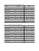
Table 1. System Dynamic Range, Options 200 or 400, and Receiver Dynamic Range, All Options Description Specification, Options 200, 400 Max Leveled Output Power (dBm) Test Port Noise Floor (dBm) (A) (B) Ports 1,31 Ports 1,31 All Ports 10 MHz to 50 MHz 93 13 50 MHz to 100 MHz 103 100 MHz to 500 MHz Typical, All Options Test Port Compression at 0.
Table 2b. System Dynamic Range at Test Port (dB), Options 219 or 419 Description 1 Specification Typical Ports 1, 31 Ports 2, 41 Ports 1, 31 Ports 2, 41 10 MHz to 50 MHz 93 93 106 104 50 MHz to 100 MHz 103 103 115 114 100 MHz to 500 MHz 117 117 130 129 500 MHz to 3.2 GHz 124 127 130 135 3.2 GHz to 8.5 GHz 127 127 135 134 8.5 GHz to 10 GHz 127 127 135 134 10 GHz to 13.5 GHz 126 125 132 131 13.
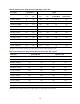
Table 2d. System Dynamic Range at Test Port (dB), Options 224 or 423 Description Specification Typical Ports 1, 31 Ports 2, 41 Ports 1, 31 Ports 2, 41 Source 1 Port 1 Combine Mode Source 2 Port 1 Combine Mode 10 MHz to 50 MHz 93 93 106 104 104 80 50 MHz to 100 MHz 103 103 115 115 112 90 100 MHz to 500 MHz 117 117 130 130 121 99 500 MHz to 3.2 GHz 124 127 130 134 127 112 3.2 GHz to 8.5 GHz 127 127 136 134 132 119 8.
Table 3b. Extended Dynamic Range at Direct Receiver Access Input (dB) - Typical Description Option 224 Options 224, 423 Ports 2, 41 Source 1 Port 1 Combine Mode Source 2 Port 1 Combine Mode 128 128 139 115 119 115 115 124 102 134 133 129 129 133 111 500 MHz to 3.2 GHz 140 140 136 139 139 124 3.2 GHz to 8.5 GHz 144 144 139 139 144 131 8.5 GHz to 10 GHz 144 144 139 139 144 131 10 GHz to 13.5 GHz 142 142 138 136 140 127 13.
N5241A, N5242A, and N5249A Corrected System Performance with 3.5mm Connectors, All Opts Note: For any Sii reflection measurement: Sjj = 0. For any Sij transmission measurement: Sji = Sij when Sij 1 Sji = 1/Sij when Sij 1 Skk = 0 for all k Applies to the N5241A, N5242A, and N5249A Option 200 or 219 or 224 or 400 or 419 or 423 analyzers with serial numbers listed below, 85131F flexible test port cable set, and a full 2-port calibration.
Transmission Uncertainty Reflection Uncertainty 13
Table 5. N4433A 4-Port Electronic Calibration Module Note: Uncertainty curves for the N4433A are created using a 2-port calibration. Multiport uncertainties are not supported at this time. Description Specification (dB) 10 MHz to 50 MHz 50 MHz to 500 MHz 500 MHz to 2 GHz 2 GHz to 8.5 GHz 8.5 GHz to 13.5 GHz 13.5 GHz to 20 GHz Directivity 50 50 50 45 45 40 Source Match 42 42 42 37 37 31 Load Match 40 41 41 35 35 29 Mag ±0.060 ±0.060 ±0.060 ±0.100 ±0.100 ±0.
Transmission Uncertainty Reflection Uncertainty 15
Table 6. N4691B 2-Port Electronic Calibration Module Description Specification (dB) 10 MHz to 50 MHz 50 MHz to 500 MHz 500 MHz to 2 GHz 2 GHz to 8.5 GHz 8.5 GHz to 13.5 GHz 13.5 GHz to 20 GHz 20 GHz to 26.5 GHz Directivity 46 46 52 46 46 46 44 Source Match 41 41 47 42 42 42 40 Load Match 40 40 46 41 41 40 38 Mag ±0.050 ±0.050 ±0.020 ±0.040 ±0.040 ±0.040 ±0.050 Phase (°) ±0.330 ±0.330 ±0.132 ±0.264 ±0.264 ±0.264 ±0.
Transmission Uncertainty Reflection Uncertainty 17
Uncorrected System Performance Specifications apply to following conditions: Over environmental temperature of 25 °C ±5 °C, with less than 1°C variation from the calibration temperature. Cable loss not included in Transmission Tracking. Crosstalk measurement conditions: normalized to a thru, measured with shorts on all ports, 10 Hz IF bandwidth, averaging factor of 8, alternate mode, source power set to the specified maximum power.
Table 7b. Source Match (dB) Description Specification Options 200, 219, 224, 400, 419, 423 Typical Options 200, 219, 224, 400, 419, 423 Option 029 Option 029 All Ports Port 1 Port 2 All Ports Port 1 Port 2 10 MHz to 50 MHz 11 9 9 14 13 12 50 MHz to 500 MHz 18 18 13 28 28 15 500 MHz to 3.2 GHz 18 17 9 22 22 12 3.2 GHz to 8.5 GHz 14 12 6 18 18 7 8.5 GHz to 10 GHz 14 12 6 18 18 7 10 GHz to 13.5 GHz 12 11 6 16 16 8 13.
Table 7d. Transmission Tracking, Reflection Tracking, Crosstalk (dB), All Options, All Ports - Typical Transmission Tracking Reflection Tracking Crosstalk 10 MHz to 50 MHz +/-1.5 +/-1.5 -84 50 MHz to 100 MHz +/-1.5 +/-1.5 -90 100 MHz to 500 MHz +/-1.5 +/-1.5 -110 500 MHz to 3.2 GHz +/-1.5 +/-1.5 -120 3.2 GHz to 8.5 GHz +/-1.5 +/-1.5 -122 8.5 GHz to 13.5 GHz +/-1.5 +/-1.5 -122 13.5 GHz to 20 GHz +/-1.5 +/-1.5 -122 20 GHz to 24 GHz +/-1.5 +/-1.5 -117 24 GHz to 26.
Test Port Output See Block diagrams for all models and options beginning on page 59. With option 029, port 1 noise tuner switch is in internal position and port 2 noise receiver switch is in normal position unless specified. Table 8. Frequency Information, All Options Description Specification (dB) Typical (dB) N5249A Frequency Range 10 MHz to 8.5 GHz -- N5241A Frequency Range 10 MHz to 13.5 GHz -- N5242A Frequency Range 10 MHz to 26.
Table 9b. Maximum Leveled Power (dBm), Options 219 or 419 Description Specification Ports 1, 31 Typical Ports 2, 41 Filt. Mode2 Hi Pwr Mode2 10 MHz to 50 MHz 8 13 50 MHz to 500 MHz 10 500 MHz to 3.2 GHz Ports 1, 31 Ports 2, 41 Filt. Mode2 Hi Pwr Mode2 13 10 19 17 13 13 11 20 19 10 10 13 11 13 18 3.2 GHz to 8.5 GHz 13 13 13 18 18 17 8.5 GHz to 10 GHz 13 13 13 18 18 17 10 GHz to 13.5 GHz 12 12 11 15 15 14 13.
Table 9d. Maximum Leveled Power (dB), Options 224 or 423 Description Specification Ports 1, 31 Typical Ports 2, 41 Filtered Mode2 Hi Power Mode2 10 MHz to 50 MHz 7 13 50 MHz to 500 MHz 8 500 MHz to 3.2 GHz Ports 1, 31 Ports 2, 41 Filtered Mode2 Hi Power Mode2 13 9 19 17 13 13 11 20 20 8 10 13 11 13 17 3.2 GHz to 8.5 GHz 13 13 13 19 19 17 8.5 GHz to 10 GHz 13 13 13 19 19 17 10 GHz to 13.5 GHz 12 12 10 15 15 14 13.
Table 9f. Maximum Leveled Power (dBm), Option 224 Description Specification Typical Source 2 Source 2 Out 1 Source 2 Out 1 Out 2 Filt. Mode2 Hi Pwr Mode2 10 MHz to 50 MHz 9 18 50 MHz to 500 MHz 11 500 MHz to 3.2 GHz Source 2 Out 2 Filt. Mode2 Hi Pwr Mode2 13 12 21 18 18 17 13 22 21 10 14 14 13 17 19 3.2 GHz to 8.5 GHz 18 18 18 22 22 22 8.5 GHz to 10 GHz 18 18 18 22 22 22 10 GHz to 13.5 GHz 16 16 16 21 21 20 13.
Table 9h. Maximum Leveled Power (dBm), Options 224 or 423 with 0291, Combine Mode - Typical Description Source 1 Port 1 Source 2 Port 1 Filtered Mode2 Hi Power Mode2 Filtered Mode2 Hi Power Mode2 10 MHz to 50 MHz 6 16 -8 2 50 MHz to 500 MHz 9 17 -5 4 500 MHz to 3.2 GHz 9 10 -5 -4 3.2 GHz to 8.5 GHz 15 15 2 2 8.5 GHz to 10 GHz 15 15 2 2 10 GHz to 13.5 GHz 11 11 -2 -2 13.
Table 11a. Power Level Linearity1 (dB), All Options - Specification Ports 1, 32 -25 dBm ≤ P <-20 dBm Ports 1, 32 -20 dBm ≤ P <-15 dBm Ports 1, 32 P ≥-15 dBm 10 MHz to 50 MHz +/-2.0 +/-1.5 +/-1.0 50 MHz to 500 MHz +/-1.5 +/-1.0 +/-1.0 500 MHz to 8.5 GHz +/-1.0 +/-1.0 +/-1.0 8.5 GHz to 13.5 GHz +/-1.0 +/-1.0 +/-1.0 13.5 GHz to 26.5 GHz +/-1.0 +/-1.0 +/-1.0 Description 1 Referenced 2 Either to nominal power. port can be used as the source port. Source in filtered mode. Table 11b.
Table 12a. Power Sweep Range (dB), Options 200 or 400 Description Specification Typical Ports 1, 31 Ports 2, 41 Ports 1, 31 Ports 2, 41 10 MHz to 50 MHz 33 38 46 44 50 MHz to 500 MHz 35 38 48 47 500 MHz to 3.2 GHz 35 38 40 45 3.2 GHz to 8.5 GHz 38 38 47 46 8.5 GHz to 10 GHz 38 38 47 46 10 GHz to 13.5 GHz 38 38 44 43 13.5 GHz to 16 GHz 38 38 44 43 16 GHz to 20 GHz 38 35 43 39 20 GHz to 24 GHz 37 32 42 38 24 GHz to 26.
Table 12c. Power Sweep Range (dB), Options 219 or 419 with 0291 Description Specification Typical Port 12 Port 22 Port 12 Port 22 10 MHz to 50 MHz 32 38 45 44 50 MHz to 500 MHz 34 38 46 46 500 MHz to 3.2 GHz 34 38 39 45 3.2 GHz to 8.5 GHz 37 38 44 44 8.5 GHz to 10 GHz 37 38 44 44 10 GHz to 13.5 GHz 37 34 42 39 13.5 GHz to 16 GHz 37 34 42 39 16 GHz to 20 GHz 35 30 40 34 20 GHz to 24 GHz 33 27 39 31 24 GHz to 26.
Table 12e. Power Sweep Range (dB), Option 224 Description Specification Typical Source 2 Out 11 Source 2 Out 2 Source 2 Out 11 Source 2 Out 2 10 MHz to 50 MHz 24 28 38 35 50 MHz to 500 MHz 26 32 39 38 500 MHz to 3.2 GHz 25 29 34 36 3.2 GHz to 8.5 GHz 33 33 39 39 8.5 GHz to 10 GHz 33 33 39 39 10 GHz to 13.5 GHz 31 31 38 37 13.5 GHz to 16 GHz 31 31 38 37 16 GHz to 20 GHz 30 28 36 34 20 GHz to 24 GHz 28 27 35 34 24 GHz to 26.
Table 13. Nominal Power (Preset Power, dBm) Options 200, 400 Options 219, 224, 419, 423 All Ports1 Ports 1, 2, 3, 41 Source 2 Out 1 Source 2 Out 2 Source 1 Port 1 Combine Mode Source 2 Port 1 Combine Mode N5241A 0 -5 -5 -5 -5 -5 N5242A 0 -5 -5 -5 -5 -5 N5249A 0 -5 -5 -5 -5 -5 Description 1 Any Option 224 Options 224, 423 port can be used as the source port. Table 14.
Table 16. Non-Harmonic Spurs (dBc) at Nominal Power, All Options, All Ports - Typical Description Based on 8 kHz offset Frac-N 10 MHz to 500 MHz -50 500 MHz to 2 GHz -60 2 GHz to 4 GHz -57 4 GHz to 8 GHz -51 8 GHz to 8.5 GHz -45 8.5 GHz to 13.5 GHz -45 13.5 GHz to 16 GHz -45 16 GHz to 24 GHz -39 24 GHz to 26.5 GHz -33 Table 17.
Test Port Input Table 18. Noise Floor1 (dBm) at 10 Hz IFBW, All Options, All Ports Description Specification Typical Test Port Direct Receiver Access Input Test Port Direct Receiver Access Input 10 MHz to 50 MHz2 -80 -- -87 -130 50 MHz to 100 MHz2 -90 -- -95 -128 100 MHz to 500 MHz2 -104 -- -110 -132 500 MHz to 2 GHz -114 -- -117 -133 2 GHz to 8.5 GHz -114 -- -117 -129 8.5 GHz to 13.5 GHz -114 -- -117 -129 13.
16 GHz to 24 GHz <0.23 24 GHz to 26.5 GHz <0.29 1 Test port receiver compression at specified input levels below 500 MHz is negligible due to coupler roll. Table 21a. Trace Noise1 Magnitude (dB rms), All Options, All Ports Description 1 Specification Typical 1 kHz IFBW 1 kHz IFBW 100 kHz IFBW 600 kHz IFBW 10 MHz to 100 MHz 0.007 0.0039 0.040 0.140 100 MHz to 8.5 GHz 0.002 0.0005 0.005 0.011 8.5 GHz to 13.5 GHz 0.002 0.0005 0.005 0.011 13.5 GHz to 16 GHz 0.002 0.0005 0.005 0.
Table 23. Stability1 - Typical Description 1 Magnitude (dB/°C) Phase (°/°C) 10 MHz to 50 MHz 0.01 0.29 50 MHz to 500 MHz 0.01 0.06 500 MHz to 3.2 GHz 0.01 0.07 3.2 GHz to 8.5 GHz 0.02 0.13 8.5 GHz to 10 GHz 0.02 0.13 10 GHz to 13.5 GHz 0.02 0.13 13.5 GHz to 16 GHz 0.02 0.13 16 GHz to 20 GHz 0.03 0.40 20 GHz to 24 GHz 0.03 0.54 24 GHz to 26.5 GHz 0.04 0.56 Stability is defined as a ratio measurement made at the test port. Table 24.
Noise Receiver Input (Option 029 only) Table 25. Noise Receiver Bandwidth Description 1 Bandwidth 10 MHz to 25 MHz 800 kHz, 2 MHz 25 MHz to 60 MHz 800 kHz, 2/4 MHz 60 MHz to 150 MHz 800 kHz, 2/4/8 MHz1 150 MHz to 26.5 GHz 800 kHz, 2/4/8/24 MHz1 8 and 24 MHz bandwidths are available only with calibration using noise source. Table 26. Receiver Noise Figure (dB), Port 2, at All BW, High Gain Setting Description Specification Typical 10 MHz to 200 MHz 9.0 -- 200 MHz to 2 GHz 12.
Table 28. Noise Receiver Linearity (dB) at 4 MHz BW - Specification Power Range (dBm) Specification Low Gain Setting Reference to -60 dBm Medium Gain Setting Reference to -60 dBm High Gain Setting Reference to -60 dBm -34 to -64 -48 to -76 -58 to -84 +/-0.05 -64 to -70 -76 to -86 -84 to -92 +/-0.10 Table 29. Noise Receiver Input Range - Specification Description Max Input Power (dBm) for <0.
Dynamic Accuracy Table 30. Dynamic Accuracy - Specification Standard receiver accuracy of the test port input power reading relative to the reference input power level. It is verified with the following measurements: Compression over frequency IF linearity at a single frequency of 1.998765 GHz using a reference level of -20 dBm for an input power range of 0 to -60 dBm. For value below -60 dBm, refer to “VNA Receiver Dynamic Accuracy Specifications and Uncertainties”.
Dynamic Accuracy, 1 GHz Dynamic Accuracy, 8.
Dynamic Accuracy, 13.5 GHz Dynamic Accuracy, 20 GHz Dynamic Accuracy, 26.
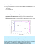
Table 31. Test Port Input (Group Delay)1 Description Typical Performance Aperture (selectable) (frequency span)/(number of points -1) Maximum Aperture 20% of frequency span Range 0.5 x (1/minimum aperture) Maximum Delay Limited to measuring no more than 180° of phase change within the minimum aperture.) Accuracy See graph below. Char. The following graph shows characteristic group delay accuracy with full 2-port calibration and a 10 Hz IF bandwidth.
General Information Miscellaneous Information Front Panel Rear Panel Environment and Dimensions Table 32. Miscellaneous Information Description Supplemental Information System IF Bandwidth Range 1 Hz to 15 MHz, nominal (7 MHz, 10 MHz, and 15 MHz IFBWs are available ONLY with FW A.09.42 and later, and with DSP version 5) CPU Intel 2.0 GHz Core i7. Note: Some instruments may have a different CPU. For the latest information on CPUs and associated hard drives, visit: http://na.tm.agilent.
Table 33. (Continued) Front Panel Information, All Options Description Typical Performance Display Range Magnitude +/-2500 dB (at 500 dB/div), max Phase +/-2500° (at 500 dB/div), max Polar 10 pUnits, min 10,000 Units, max Display Resolution Magnitude 0.001 dB/div, min Phase 0.01°/div, min Marker Resolution Magnitude 0.001 dB, min Phase 0.01°, min Polar 10 pUnit, min Table 34.
Table 34. (Continued) Rear Panel Information, All Options Description Typical Performance External IF Inputs Function Allows use of external IF signals from remote mixers, bypassing the PNA's first converters Connectors SMA (female); A, B, C, D, R (4-port); A, B, R1, R2 (2-port) Frequency Path DSP Version IF Bandwidth RF Frequency IF Frequency Normal IF path: 4 All < 53 MHz 2.535211 MHz All >= 53 MHz 7.605634 MHz <= 600 kHz < 53 MHz 2.479339 MHz >= 53 MHz 7.438017 MHz 1 MHz All 7.
Table 34. (Continued) Rear Panel Information, All Options Description Typical Performance RF Pulse Modulator Input (Source Modulator) On/Off Ratio 10 MHz to 3.2 GHz -64 dB 3.2 GHz to 8.5 GHz -80 dB 8.5 GHz to 13.5 GHz -80 dB 13.5 GHz to 26.5 GHz -80 dB Pulse Period Minimum 20 ns Maximum 70 s Pulse Outputs Voltage (TTL) Impedance High: 3.3 V to 3.
Table 34. (Continued) Rear Panel Information, All Options Description Typical Performance VGA Video Output Connector 15-pin mini D-Sub; Drives VGA compatible monitors Devices Supported: Resolutions: Flat Panel (TFT) 1024 X 768, 800 X 600, 640 X 480 Flat Panel (DSTN) 800 X 600, 640 X 480 CRT Monitor 1280 X 1024, 1024 X 768, 800 X 600, 640 X 480 Simultaneous operation of the internal and external displays is allowed, but with 640 X 480 resolution only.
Table 35. Analyzer Dimensions and Weight All N5241A, N5242A, and N5249A models are shipped with bottom feet, handles, and front and rear hardware. See detailed PNA dimension drawings at: http://na.tm.agilent.com/pna/PNADimensions.pdf Cabinet Dimensions Metric (mm) Imperial (inches) Without bottom feet: EIA RU1 = 6 266.1 10.5 With bottom feet 279.1 11.0 Without handles or rack-mount flanges 425.6 16.8 With handles, without rack-mount flanges 458.7 18.1 With handles and rack-mount flanges 482.
Measurement Throughput Summary Typical Cycle Time for Measurement Completion Cycle Time vs. IF Bandwidth Cycle Time vs. Number of Points Data Transfer Time Cycle time Includes sweep time, retrace time and band-crossing time. Analyzer display turned off with DISPLAY:ENABLE OFF. Add 21 ms for display on. Data for one trace (S11) measurement. Table 36a.
Table 36b. Cycle Time (ms) for Full-Span Measurement Completion - Typical 10 MHz to 26.5 GHz IF Bandwidth 600 kHz 10 kHz 1 kHz Number of Points 201 401 1601 16001 Uncorrected 59 69 118 350 2-Port cal 125 147 244 707 Uncorrected 94 156 480 2333 2-Port cal 196 320 968 4674 Uncorrected 277 504 1873 17950 2-Port cal 561 1015 3756 35900 Table 37. Cycle Time vs.
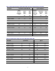
Table 38. Cycle Time vs. Number of Points Applies to the Preset condition (correction off) except for the following changes: CF = 10 GHz Span = 100 MHz Display off (add 21 ms for display on) Cycle time includes sweep and retrace time. Description Number of Points IF Bandwidth (Hz) 1,000 10,000 30,000 600,000 3 7.7 5.44 5.7 5.4 11 16.6 7.90 5.9 5.4 51 60 10.7 6.5 5.5 101 115 16.8 8.2 5.6 201 222 29.0 11.8 5.9 401 436 53.0 18.8 6.3 801 860 102 32.8 7.
Table 39. Data Transfer Time1 (ms) - Typical Description Number of Points 201 401 1601 16,001 SCPI over GPIB (Program executed on external PC2) 32-bit floating point 5.6 10.5 39.9 400 64-bit floating point 10.5 20.3 79.2 788 46 92.5 370 3702 ASCII SCPI over SICL/LAN or TCP/IP Socket (Program executed in the analyzer) 32-bit floating point 0.18 0.21 0.5 3.6 64-bit floating point 0.22 0.28 0.62 5.3 ASCII 6.3 12.3 47.3 470 32-bit floating point <0.15 0.15 0.2 0.
Specifications: Front-Panel Jumpers Note: All PNA-X options have the following front-panel jumpers for each port. Measurement Receiver Inputs Reference Receiver Inputs and Reference Source Outputs Source Outputs Coupler Inputs Damage Level Table 40. Measurement Receiver Inputs (dBm) - Typical (RCVR A, B, C, D IN) @ 0.1 dB Typical Compression Description All Options 10 MHz to 50 MHz -4 50 MHz to 500 MHz -3 500 MHz to 8.5 GHz -2 8.5 GHz to 13.5 GHz -2 13.
1 In Filtered Mode, the signal path goes through filters to minimize harmonics below 3.2 GHz. In Hi Power Mode, the signal bypasses the filters to maximize output power. Table 41b.
10 GHz to 13.5 GHz 1 1 -2 13.5 GHZ to 16 GHz 1 1 -2 16 GHZ to 20 GHz 0 0 -4 20 GHZ to 24 GHz -2 -2 -6 24 GHZ to 26.5 GHz -10 -10 -10 1 In Filtered Mode, the signal path goes through filters to minimize harmonics below 3.2 GHz. In Hi Power Mode, the signal bypasses the filters to maximize output power. Table 42a.
3.2 GHz to 8.5 GHz 14 14 14 8.5 GHz to 10 GHz 14 14 14 10 GHz to 13.5 GHz 14 14 12 13.5 GHZ to 16 GHz 14 14 12 16 GHZ to 20 GHz 12 12 9 20 GHZ to 24 GHz 9 9 7 24 GHZ to 26.5 GHz 2 2 4 1 In Filtered Mode, the signal path goes through filters to minimize harmonics below 3.2 GHz. In Hi Power Mode, the signal bypasses the filters to maximize output power. Table 43.
Test Set Block Diagrams NOTE: For best readability, use a color printer for printing the following graphics. Legend Figure 1. 2-Port N5241A, N5242A, and N5249A Base Unit Option 200 Figure 2.
Figure 3. 2-Port N5241A, N5242A, and N5249A Option 224 Figure 4.
Figure 5. 4-Port N5241A, N5242A, and N5249A Base Unit Option 400 Figure 6.
Figure 7. 4-Port N5241A, N5242A, and N5249A Option 423 Figure 8.
Figure 9.
Agilent Email Updates www.agilent.com www.agilent.com/find/pnax www.agilent.com/find/emailupd ates For more information on Agilent Technologies’ products, applications or services, please contact your local Agilent office. The complete list is available at: Get the latest information on the products and applications you select. www.agilent.com/find/contactus Americas . www.axiestandard.