
Instruction Manual

3 ww w.bk precision.com
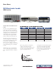
DC Electronic Loads
M
odels 8500, 8502, 8510, 8512, 8514, 8518, 8520, 8522, 8524, 8526
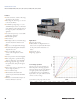
Rear panel
▲
2
1)
Air vents
Temperature-controlled fan expels air through
these vents to keep the temperature constant
inside the system.
2)
Trigger and remote sensing terminal
block
Connect sensing lines to this terminal to
compensate for voltage drops due to load wire
resistance. This terminal block also contains the
two connections for the remote TTL trigger input
signal.
1
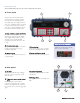
Front panel
▲
1 2
3 4 5
The numeric keys and rotary knob provide a
convenient interface for setting the operating
mode and desired current/voltage/resistance
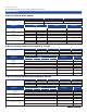
levels quickly and precisely. Voltage and current
can be set to a maximum resolution of 1 mV and
0.1 mA respectively (models 8500 and 8502
only). Up to 25 different instrument setups can
be stored and recalled from internal memory.
1
) High resolution, easy to read display
Displays set values and measured values.
Current/voltage and power/resistance displays
can be toggled. Display resolution for current
and voltage is user-selectable. Maximum
resolution for model 8500 and 8502 is 1 mV/
0.1 mA.
2)
Convenie nt data entry
Rotary knob for quick analog-style control. Turn
to adjust a setting value. Press to toggle
measurement display mode.
3)
Numeric keypad
Conveniently enter set values directly and access
secondary functions.
4)
Function keys
Activate current, voltage, power, or resistance
modes and scroll through menus and options.
5)
Front panel load termi nals
Connect to device under test. Hex-head screw
Hex-head sc rew t erminals
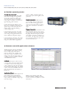
3
) Interface connection
Serial interface connector for RS232 or USB
communication.
4)
Voltage switch
Line voltage selection switch (110 VAC or 220
VAC).
terminals are used for models 8518 and
8520 – 8526 to connect wires.
3 4