
Owner's manual

www.ProgrammablePower.com268
3091LD
analyzed quickly without the need to hook up
additional test equipment. A Windows graphical
user interface (GUI) is provided to expand the
measurement and display capabilities of the
3091LD. The GUI can be used to save and print
test results for report purposes.
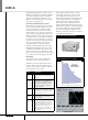
Crest Factor and Power Factor control
When operating in constant current or constant
power mode, the 3091LD supports crest factor
control by narrowing the conduction angle of
the current waveform in order to match the
requested crest factor. Thus, the peak current is
increased while retaining the RMS current level.
While the apparent power remains constant, the
true power decreases. This results in a reduced
true power factor. Consequently, as crest factor
is increased, the true power factor automatically
decreases. The load further controls power
factor by shifting the current with respect to
the input voltage (displacement power factor).
Both leading and lagging power factor control
is available. A phase shift of the current is only
possible if the crest factor is higher than 1.414.
Thus, crest factor and power factor control ranges
are coupled as shown in the graph to the right.
Front Panel
The large LCD screen is used to display setup
information as well as measurement data.
Measurements include volt RMS, volt peak,
current RMS, current peak, crest factor, true
power, apparent power, power factor and
frequency. Both voltage and current waveforms
at the load input terminals can be digitized
and displayed on the front panel graphical
LCD. This allows EUT output behavior to be
analyzed quickly without the need to hook up
additional test equipment. A Windows graphical
user interface (GUI) is provided to expand the
measurement and display capabilities of the
3091LD. The ICS can be used to save and print
test results for report purposes.
The 3091LD can be used to emulate a wide variety of
AC load conditions to support real-world testing and
evaluation of UPS and AC source products. Specically,
the following modes can be selected:
Mode Description
Constant
Power
CP This mode effectively emulates constant
power loads such as switching power
supplies
Constant
Resistance
CR Emulates a conventional resistive load or
power resistor. A programmable range
from 2.5 Ohms to 1000 Ohms covers a
wide range of applications. This mode
can be used to replace conventional
resistive load banks.
Constant
Current
CC Provides a constant current load. This
mode may be used to simulate both linear
(resistive) and non-linear (active loads for
voltage regulation testing.
Constant
Voltage
CV This mode emulates a shunt regulator
load and may be used to test current
source products.
Short
circuit
SC Test the short circuit protection mode of
the EUT by providing a short condition.
The 3001LD can handle surge currents
of up to 300 Amps for up to 50 msec and
sustained currents of 30 Amps in this
mode of operation. The low voltage
cut-off of the load can be programmed
from 50 Volts up.
Power & Crest Factor Control Range
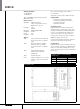
Load Power Rating curve for 3091LD