
User guide
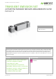

DATA SHEET > Transient Emission Set > 20130814
TECHNICAL DETAILS
BS 200N100 - ELECTRONIC SWITCH
SPECIFICATION
Operation voltage Max. 60V DC
Operation current Max. 100A continuous
Peak voltage Max. 1,000V
Inrush current Max. 400A for 200ms
Voltage drop < 1.2V at 100A
< 0.2V at 25A
Overvoltage
protection
By varistors
Overload
protection
Short-circuit protected
Reverse-polarity protected
SWITCH CHARACTERISTICS
Switching time 300ns +/- 20% into test load
50uH/0.6ohm
On/Off time 10ms to 500ms, continuously
selectable via potentiometer
Operation mode Indicatied by LED
TRIGGER
Manual Manual trigger of a single event
Auto Automatic trigger with min. 0.1Hz to
max. 1Hz repetition, continuously
selectable by potentiometer
External In Enternal trigger, negative going
edge 0V, BNC input 10V
MEASUREMENT
Voltage monitor BNC output; divider 1:200 +/-5%
Trigger Out BNC output; negative going edge 0V
GENERAL DATA
Dimensions,
weight
90mm x 125mm x 120mm (LxWxH)
(without connecting sockets)
approx. 1.3kg
Supply voltage 24V DC via mains supply adapter
AN 200N100 - ARTIFICIAL NETWORK
TECHNICAL DATA
as per ISO 7637-2, CISPR 25, ISO 11452-4
and CISPR 16-1-2, switchable
Frequency range 0.1 to 125MHz
Operation voltage 1,000V DC/250V AC up to 1kHz
Operation current Max. 100A AC/DC continuous
Inrush current Max. 400A for 200ms
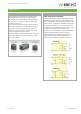
Impedance 5uH // 50ohm
for details see diagrams on page 2
Insertion loss less than 3dB DUT to receiver output
Inductance 5uH +/-10% air-core coil
Coupling
capacitor
0.1uF
CONNECTIONS
Power supply/DUT
connection
High-current connectors up to 100A
4mm safety lab connectors up to 32A
Test output BNC-connection
GENERAL DATA
Dimensions 318 x 126 x 122 mm (L x W x H)
(without connecting sockets)
Weight approx. 2.8kg
www.emtest.com © EM TEST > PAGE 3/5