
User Manual

DATA SHEET > UCS 500N5 > 20131118
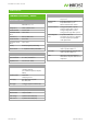
TECHNICAL DETAILS
COMBINATION WAVE / SURGE
SURGE MODULE, VCS/N5
As per EN/IEC 61000-4-5 and
EN 61000-6-1, -6-2
Voltage (o.c.) 160V - 5,000V ± 10%
Pulse front time 1.2us ± 30%
Pulse time to half
value
50us ± 20%
Current (s.c.) Max. 2,500A ± 10%
Pulse front time 8us ± 20%
Pulse time to half
value
20us ± 20%
Polarity Positive/negative/alternating
Event counter 1 - 30,000 or endless, selectable
TRIGGER CIRCUIT
Release of pulses Automatic, manual, external
Synchronization 0° - 360°, resolution 1°
Repetition rate max. 1Hz (1s - 999s)
OUTPUTS
Direct Via HV connectors for external
coupling networks
(Zi = 2ohm with optional adapter
IMN 2)
Coupling mode Line to line
Line(s) to ground
DUT supply AC: 300V/16A; 50/60Hz
DC: 300V/16A
CRO trigger 5V trigger signal for oscilloscope
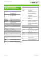
MEASUREMENTS
CRO Û-monitor 10Vp at 5,000V
CRO Î-monitor 10Vp at 2,500A
Peak voltage 5,000V in the LCD display
Peak current 2,500A in the LCD display
TEST ROUTINES
Quick Start One-line adjustable parameters,
easy-to-use
Standard Test
routines
As per IEC 61000-4-5, Levels 1 - 4
As per EN 61000-6-1, -6-2
Manual Standard Test routine
User Test routines Change polarity after n pulses
Change coupling after n pulses
Change voltage after n pulses
Change phase angle after n pulses
Pulsed Magnetic
Field
as per IEC 61000-4-9
Test levels 100, 300 and 1,000A/m
Test level steplessly adjustable
under Quick Start
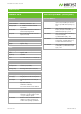
OPTIONS
CNV504Nx Coupling network for 4 signal/data
lines as per IEC 61000-4-5
CNV508Nx Coupling network for 8 signal/data
lines as per IEC 61000-4-5
IMN 2 Impedance matching adapter to
match direct output to 2ohm source
impedance
www.emtest.com © EM TEST > PAGE 5/8