
User Manual

2
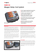
SMRT36
Megger Relay Test System
Each voltage channel can provide variable outputs of 0- 30/150/
300 Volts at 150 VA of output power, and has a unique flat power
curve from 30 to 150 Volts insuring maximum output power to the
load at all times. With the voltage channel converted to current, a
three channel unit can provide 6 currents for testing three phase
current differential relays, including harmonic restraint transformer
differential relays.
Using the Ethernet ports, the SMRT36 is literally a “plug-and-
play” unit, where voltage and current outputs can be seamlessly
synchronized with other SMRT units outputs for testing more
complex test applications such as back-to-back tests, or 9 up to12
phase current test applications.
FEATURES AND BENEFITS
Constant Power Output – New higher powered Voltage-Current
amplifiers. The current amplifier delivers maximum compliance
voltage to the load constantly during the test, and range changing
is done automatically under load. This insures better test results,
and saves time by not having to turn the outputs off to change
ranges. Constant power output in many cases eliminates the need
to parallel or series current channels together to test high burden
relays.
High Output Current – Provides up 30 Amps at 200 VA per phase
continuous, or up to 60 Amperes at 300 VA with a 1.5 second duty
cycle. The three current amplifiers can be paralleled to provide a
maximum of 180 Amperes at 900 VA, for testing all instantaneous
overcurrent relays.
New PowerV
TM
Voltage Amplifier High Power Output –
The SMRT provides a new higher VA power output on the voltage
channel at the lower critical test voltages (from 30 to 150 Volts).
Customers who want to test a panel of relays at one time find it
impossible using lower VA rated voltage.
Convertible Voltage Channels – With a 3 channel SMRT36 unit,
convertible channels in conjunction with the three main current
channels, provides 6 currents for testing three phase current
differential relays. With all six currents in parallel the unit can
provide a maximum single phase output of 225 Amperes for short
durations.
High resolution and accuracy – Metered outputs provides
extremely high accuracy needed for testing a wide variety of
devices. With metered values, what you see is what you get.
Steady-State and Dynamic testing capability – The SMRT36
provides, either through manual control or computer control, both
steady-state and dynamic testing of protective relays. This includes
programmable waveforms with dc offset and harmonics.
Output current and voltage sine waves are generated
digitally – Outputs do not vary with sudden changes in input
voltage or frequency, which increases test accuracy and reduces
testing time.
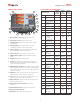
Modular design – Output modules plug-in and out easily for
system re-configuration and maintenance.
Built-in Transducer Testing Capability – The SMRT36P
incorporates high accuracy amplifiers, an optional transducer DC
input and test algorithms to test transducers easily and effectively.
Digital binary inputs and outputs – The programmable binary
inputs, and programmable outputs provide timing and logic
operations in real-time with the output voltage and currents. Binary
Inputs can be programmed, using Boolean logic, for more complex
power system simulations. This provides a low cost, closed loop,
power system simulator.
Circuit breaker simulator – Binary outputs provide programmable
normally closed and normally open contacts to simulate circuit
breaker operation for testing reclosing relays. Sequence of
operation, timing, and lockout are easily tested.
Performs transient tests – Perform acceptance or troubleshooting
tests by replaying digitally recorded faults or EMTP/ATP simulations
in the IEEE- C37.111, COMTRADE Standard format.
Perform End-to-End tests – Using AVTS software and a portable
GPS satellite receiver, the SMRT performs satellite-synchronized end-
to-end dynamic multi-state or playback transient COMTRADE files
either for commissioning or troubleshooting tests.
Wide-ranging output frequency – The output frequency of the
current and voltage channels can be set for any frequency from dc
to 1 kHz. Popular test frequencies such as 16.66, 25, 33, 50, 60,
100,120, 125, 150, 180, 250, 300 and 400 Hz are easily set and
controlled. Multi-purpose test system saves time and money.
USB 2.0 interface port – The USB port provides a PC interface for
automated control of the SMRT unit. Also provides secure isolation
when testing IEC 61850 devices (for customers who require secure
isolation from their IEC 61850 substation bus).
Three Ethernet ports – PC/OUT Ethernet Port is the primary PC
connection port. The IN/IEC61850 Ethernet Port provides interface
to multiple SMRT units, and may be used to connect to the IEC
61850 substation bus. The OUT Ethernet Port is primarily used to
interconnect multiple SMRT units together for synchronous multi-
unit operation. The STVI PoE (Power over Ethernet) port and is used
to connect to the STVI.
Bluetooth – Optional Bluetooth provides more flexibility. A wireless
interface between the PC and SMRT, in conjunction with the SMRT
IEC 61850 Ethernet port, provides the isolation required for a secure
substation access interface between the SMRT and the IEC 61850
substation network.
Universal input voltage – Operation from 90 to 264 Vac, 50/60
Hz, the SMRT can use virtually any standard source in the world.
Immediate error indication – Audible and visual alarms indicate
when amplitude or waveforms of the outputs are in error.
Optional Transducer Testing Capability – This optional hardware
feature (see Ordering Information) provides transducer DC Inputs to
test transducers easily and effectively. The STVI software is designed
to automatically recognize the Transducer DC Inputs, and thus
provide the Transducer Test Screen when selected. AVTS software
comes standard with Transducer Test Modules, which will provide
automatic transducer test capability in conjunction with the optional
hardware.